GROUND MOUNT INSTALLATION MANUAL
Contents DISCLAIMER 1 RATINGS 2 MARKINGS 2 CHECKLIST 3 1. BUILD BASE 4 1. BUILD BASE 5 2. CONNECT SUBSTRUCTURE 5 3. PLACE RAILS 6 4. SECURE LUGS 6 5.
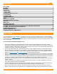
RATINGS UL 2703 LISTED #5003225 • Conforms to STD UL 2703 (2015) Standard for Safety First Edition: Mounting Systems, Mounting Devices, Clamping/ Retention Devices, and Ground Lugs for Use with Flat-Plate Photovoltaic Modules and Panels. • Certified to CSA STD LTR AE-001-2012 Photovoltaic Module Racking Systems. • Max Overcurrent Protective Device (OCPD) Rating: 25A • Max Module Size: 25.6 ft² • Max Frameless Module Size for Canadian LTR-AE: 21.
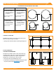
CHECKLIST PRE-INSTALLATION IRONRIDGE COMPONENTS ☐ Verify module compatibility. See Page 14 for info. ☐ Purchase 2” or 3” (NPS) ASTM A53 Grade B SCH 40 Pipe, galvanized to a min of ASTM A653 G90 or ASTM A123 G35, or 2.375” or 3.500” (O.D.
PIPE SPECIFICATIONS TESTED AND EVALUATED PIPE AND TUBE Approved 2” Pipe Approved 3” Pipe ALLIED MECH TUBING 12 GA 50 ksi yield strength • • Galvanized (Allied flotcoat, Gatorshield, or Hot Dipped) ALLIED MECH TUBING 8 GA 45 ksi yield strength • • Galvanized (Allied flotcoat, Gatorshield, or Hot Dipped) top cap set screw install torque: 11-ftlbs top cap set screw install torque: 16-ftlbs SCHEDULE 40 PIPE • ASTM A53 GR B • 35 ksi yield strength • Hot Dipped Galvanized SCHEDULE 40 PIPE • ASTM A53 GR B •
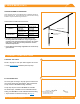
1. BUILD Build BASE Base (CONT.) GROUND SCREW FOUNDATIONS Follow respective Ground Screw Manufacturer’s installation methods for driving screws into soil. Insert vertical piers into ground screws, ensuring at least 18” of pier is inserted into ground screw. Tested and/or Evaluated Ground Screws 2” System 3” System Manufacture Model # American Ground Screws N76 American Ground Screws N102 Krinner North America KSF G76 Krinner North America KSF G114 Friction Bolt Torque Specification SCHD.
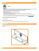
3. Place Rails A. ATTACH HARDWARE A On the ground, attach Rail Connector brackets to rail by sliding 3/8”-16 bonding bolts into side slot. Space out to match pier spacing. With brackets in place, finger tighten flange nuts onto bolts. ➢ Tape ends of rail, to keep bolts from sliding out while moving. B. FASTEN CONNECTORS Center rails on cross pipes, leaving equal distance on ends. Secure with Rail Connector hardware: 3/8”-16 U-bolts, flange nuts, flat washers, and lock washers.
5. SECURE MODULES A. SECURE FIRST END A UFO 80 in-lbs Place first module in position on rails, a minimum of 1” from rail ends. Snap Stopper Sleeves onto UFO. Fasten module to rail using the UFO, ensuring that the UFO is hooked over the top of the module. Torque to 80 in-lbs. ➢ Ensure rails are square before placing modules. ➢ Hold Stopper Sleeves on end while torquing to prevent rotation. ➢ If using CAMO instead of UFO + Stopper Sleeve, refer to Page 7 for CAMO installation procedure. B.
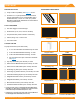
CAMO A. SLIDE INTO RAIL A Slide CAMO into rail channel far enough to clear the module frame. CAMO requires 6" of clearance from end of rail. B. PLACE MODULE 6" Cle ara nc e B Place module on rails (module cells not shown for clarity). When installing CAMO the module can overhang the rail no more than 1/4”. C. PULL TOWARDS END C Pull CAMO towards rail ends, at 45 degree angle, so the bonding bolt contacts the module flange edge. D.
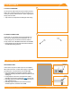
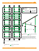
ELECTRICAL DIAGRAM * UFO or UFO Clamp CAMO Grounding Lug * Fault Current Ground Path Min 10 AWG Copper Wire Cross Pipe Rail Optional Cross Brace Cross Pipe Grade Optional Ground Screws Bonding Points Fault Current Ground Path Section View Plan View *Grounding Lugs and wire are not required in systems using certain Enphase microinverters or certain Sunpower modules.
DIAGONAL BRACES (OPTIONAL) Slide sleeve on north pier 2-3” above the ground (6” max). Attach Diagonal Brace to sleeve with 1/2” hardware. Slide second sleeve up on south pier 2-3” below top cap (6” max). Raise Diagonal Brace to align holes in sleeve and brace. Attach hardware and raise sleeve to full extent. Torque Diagonal Brace bolts to 40 ft-lbs. Torque set screws to 15 ft-lbs.
SPLICING CROSS PIPE The following instructions should be followed, when required, to join more than one section of cross pipe together to ensure bonding is maintained throughout the system. A A. ALLIED MECHANICAL TUBING SPLICES Mechanical tube splices shown in the table below shall be of equivalent Allied Flowcoat or Gatorshield zinc coating. Mechanical Tube Size of the Structure Splice Tube Size 2.375” OD, 12 Gauge 2.000” OD, 9 Gauge, Minimum 12” Long 3.500” OD, 8 Gauge 3.
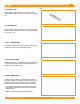
MICROINVERTER KITS Use IronRidge's Microinverter Kit to bond compatible microinverters and power optimizers to the racking system. Insert Microinverter Kit T-bolt into top rail slot. Place compatible microinverter or power optimizer into position and tighten hex nut to 80 in-lbs.
DiagonalUSING SYSTEMS Braces MICROSTORAGE (Optional) PRODUCTS Use IronRidge's Microinverter Kit to bond compatible microstroage devices to the racking system. Insert Microinverter Kit T-bolt into top rail slot. Place compatible microstorage into position and tighten hex nut to 80 in-lbs. COMPATIBLE PRODUCTS Microinverter Kit (80 in-lbs) PHAZR PHAZR Devices PHAZR-X, where X is 6-12. ➢ Running a separate equipment grounding conductor to the PHAZRs is not required.
MODULE COMPATIBILITY The Ground Mount System may be used to ground and/or mount a PV module complying with UL 2703 only when the specific module has been evaluated for grounding and/or mounting in compliance with the included instructions. Unless otherwise noted, “xxx” refers to the module power rating and both black and silver frames are included in the certification.
MODULE COMPATIBILITY Dehui Dehui modules with 30, 35 and 40mm frames DH-MYYYZ-xxx Where “YYY” can be 760, 772, 860, 872; and “Z” can be B, F or W Ecosolargy Ecosolargy modules with 35, 40, and 50 mm frames ECOxxxYzzA-bbD Where “Y” can be A, H, S, or T; “zz” can be 125 or 156; “A” can be M or P; “bb” can be 60 or 72; and “D” can be blank or B ET Solar ET Solar modules with 30, 35, 40, and 50 mm frames ET-Y6ZZxxxAA Where “Y” can be P, L, or M; “ZZ” can be 60, 72 or 72BH; and “AA” can be GL, WB, WW, BB, W
MODULE COMPATIBILITY Itek Itek Modules with 40 and 50 mm frames IT-xxx-YY Where “YY” can be blank, HE, or SE, or SE72 JA Solar JA Solar modules with 30, 35, 40 and 45 mm frames JAyyzz-bbww-xxx/aa Where “yy” can be M, P, M6 or P6; “zz” can be blank, (K), (L), (R), (V), (BK), (FA), (TG), (FA)(R), (L)(BK), (L) (TG), (R)(BK), (R)(TG), (V)(BK), (BK)(TG), or (L)(BK)(TG); “bb” can be 48, 60, or 72; “ww” can be D09, S01, S02, S03, S06, S09, S10, or S12; and “aa” can be BP, MR, SI, SC, PR, 3BB, 4BB, 4BB/RE, 5BB
Module Compatibility Phono Solar Phono Solar modules with 35, 40, and 45 mm frames PSxxxY-ZZ/A Where “Y” can be M, M1, MH, or M1H or P; “ZZ” can be 20 or 24; and “A” can be F, T, U, or TH Recom Recom modules with 35 and 40 mm frames RCM-xxx-6yy Where “yy” can be MA or MB REC Solar REC modules with 30, 38 and 45 mm frames RECxxxYYZZ Where “YY” can be AA, M, NP, PE, PE72, TP, TP2, TP2M, TP2SM, or TP2S; and “ZZ” can be blank, Black, BLK, BLK2, SLV, or 72 Renesola ReneSola modules with 35, 40 and 50 mm f
Module Compatibility SolarWorld Americas SolarWorld Sunmodule Plus, Protect, Bisun, XL, Bisun XL, may be followed by mono, poly, duo, black, bk, or clear; modules with 33 mm frames SWA-xxx Stion Stion Thin film modules with 35 mm frames STO-xxx or STO-xxxA SunEdison SunEdison Modules with 35, 40 & 50 mm frames SE-YxxxZABCDE Where "Y" can be B, F, H, P, R, or Z; "Z" can be 0 or 4; "A" can be B,C,D,E,H,I,J,K,L,M, or N ; "B" can be B or W; "C" can be A or C; "D" can be 3, 7, 8, or 9; and "E" can be 0, 1 o
Module Compatibility FRAMELESS MODULE LIST MAKE MODELS Astronergy Solar Astronergy frameless modules CHSM6610P(DG)-xxx Canadian Solar Canadian Solar frameless modules CSbY-xxx-Z Where “b” can be 3 or 6; “Y” is K, P, U, or X; and “Z” can be M-FG, MS-FG, P-FG, MB-FG, or PB-FG Heliene Heliene frameless modules YYZZxxxA Where "YY" can be72; "ZZ" can be M; and "A" can be GH Jinko Jinko frameless modules JKMxxxPP-DV Prism Solar Prism Solar frameless modules BiYY-xxxBSTC Where “YY” can be 48, 60, 60S, 7