Engineering Design Guide Solar Mounting Made Simple® Ground Mounting System 2013 Edition v1.3 A complete Guide to engineering and designing with the IronRidge Ground Mounting System.
Solar Mounting Made Simple R This Engineering Design Guide was created to help our engineering partners more easily design and specify PV mounting applications using IronRidge components. In addition to this document, IronRidge provides a complete system of technical support including installation guides, pre-stamped certification letters for most PV-friendly states, our on-line Design Assistant software, and live, knowledgeable person-to-person customer service.
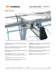
Solar Mounting Made Simple Engineering Design Guide R Overview System Overview IronRidge provides a comprehensive platform for designing a wide variety of photovoltaic systems for ground mounting applications. Due to its modular architecture, it can handle nearly all commercially available PV modules and can scale to the largest projects. IronRidge products are engineered to last in the most extreme weather conditions and have been installed in every continent in the world.
Solar Mounting Made Simple Engineering Design Guide R Overview Assembled View support@ | ironridge.com | (800) 227-9523 Page 2 2013 v1.
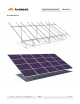
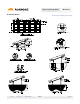
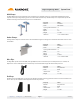
Solar Mounting Made Simple Engineering Design Guide R Overview Component View 7. Mid Clamp 4. Diagonal Brace 3. Rail Connector 5. Schedule 40 Pipe 6. End Clamp 1. Top Cap 8. Wire Clip 9. End Cap 2. IronRidge Standard Rail (XRS) For a complete 360 degree interactive viewing environment, go to: ironridge.com/products/groundmounting/360view. 1. Top Caps: Joins and aligns rail sections into single, continuous length of rail.
Solar Mounting Made Simple Engineering Design Guide R Assembly Details support@ | ironridge.com Overview Download AutoCAD File | Download PDF | (800) 227-9523 Page 4 2013 v1.
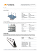
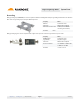
Solar Mounting Made Simple Engineering Design Guide R System Parts Top Cap The IronRidge Top Caps facilitate the quick and easy construction of a Schedule 40 substructure. Available in sizes that fit either 2” or 3” Schedule 40 pipe, this Top Cap secures quickly to multiple pier types with 3 set screws and also supports cross piping (schedule 40) with U-bolt hardware. Property Value Material ALMAG 535 Finish Mill Top Cap Sizes 2” and 3” 2” Top Cap Dimensions 3” x 4.
Solar Mounting Made Simple Engineering Design Guide R System Parts Rail Connector Our Rail Connectors secure IronRidge Standard Rails to the Schedule 40 horizontal cross pipes. Each Standard Rail requires two connectors to create a secure attachment.
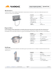
Solar Mounting Made Simple Engineering Design Guide R System Parts Mid Clamps IronRidge Mid Clamps secure PV modules to the rail when there are multiple modules in a row. The Mid Clamp fits between two adjacent modules, providing clamping pressure to both modules simultaneously. The Mid Clamps are not dependent upon the PV module’s mounting holes and fit to the top slots of our Standard Rails.
Solar Mounting Made Simple Engineering Design Guide R System Parts Grounding Wiley grounding clips (WEEB DMC) are used in conjunction with the IronRidge Mid Clamps for grounding PV modules to the Standard Rails. Order one grounding clip for every two Mid Clamps used.
Solar Mounting Made Simple R Engineering Design Guide Design Assistant Summary With the IronRidge Design Assistant™ our customers move from laboriously designing systems across the span of weeks, to intuitively designing while pricing, bill of materials and engineering calculations all update in real-time. If you register for an online account, you will then be able to save your work and prevent losing your project’s configuration settings between sessions.
Solar Mounting Made Simple R Engineering Design Guide Engineering Data Code Compliance IronRidge Ground Mount components, when installed in accordance with the IronRidge Standard Rail Installation Manual and the IronRidge Light Rail Installation Manual, will be structurally adequate and will meet the structural requirements of: • ASCE/SEI 7-05 Minimum Design Loads for Buildings & Other Structures • California Building Code, 2007 & 2010 Editions • AC428, Acceptance Criteria for Modular Framing Systems Us
Solar Mounting Made Simple R Engineering Design Guide Engineering Data Maximum Allowable EW Spans for 2” Ground Mount Exposure Wind Category Speed B 85 mph 90 mph 100 mph 110 mph 120 mph 130 mph 140 mph 150 mph support@ | Snow (psf) 0 10 20 30 40 50 60 0 10 20 30 40 50 60 0 10 20 30 40 50 0 10 20 30 40 50 0 10 20 30 40 50 0 10 20 30 40 50 0 10 20 30 40 0 10
Solar Mounting Made Simple R Engineering Design Guide Engineering Data Maximum Allowable EW Spans for 2” Ground Mount Exposure Wind Snow Category Speed (psf) 0° 5° 10 ° 15 ° 20 ° 25 ° 30 ° 35 ° 40 ° 0 119 122 104 101 96/ 91/ 88/ 87/ 88/ C 10 108 110 99 98 96/ 91/ 88/ 87/ 88/ 85 20 93 94 88 87 86/ 86/ 86/ 87/ 88/ mph 30 88 89 83 82 83 83/ 83/ 86/ 88/ 40 80 81 77 77 77 78/ 79/ 82/ 50 73 74/ 76/ 60 0 114 117 99 96 91/ 87/ 83/ 83/ 10 105 107 96 94 91/ 87/ 83/ 83/
Solar Mounting Made Simple R Engineering Design Guide Engineering Data Maximum Allowable EW Spans for 3” Ground Mount Exposure Wind Snow Category Speed (psf) 0° 5° 10 ° 15 ° 20 ° 25 ° 30 ° 0 242 248 215 209 198 190 183 B 10 206 209 193 191 189 187 183 85 20 174 176 166 165 166 168 169 mph 30 162 164 156 156 158 160 163 40 145 145 143 143 146 149 153 50 136 140 145 60 138 0 232 238 205 199 189 181 174 10 202 204 188 185 183 181 174 90 20 171 173 163 162 162 16
Solar Mounting Made Simple R Engineering Design Guide Engineering Data Maximum Allowable EW Spans for 3” Ground Mount Exposure Wind Snow Category Speed (psf) 0° 5° 10 ° 15 ° 20 ° 25 ° 30 ° 35 ° 0 208 214 182 177 168 160 153/ 153/ C 10 189 192 174 171 167 160 153/ 153/ 85 20 163 165 154 152 151 151 151/ 153/ mph 30 153 155 145 144 145 145 146/ 150/ 40 141 142 135 134 135 137 139/ 144/ 50 128 130 133 60 0 199 204 174 169 159 152 146/ 145/ 10 183 187 168 165 15
Solar Mounting Made Simple R Engineering Design Guide Engineering Data Ground Mount Foundation Requirements The foundation requirements for a cast-in-place drilled concrete pier system may be obtained from Tables 3 & 4. These tables are based on the piers being installed at their maximum allowable spacing. For spacing’s less than maximum and for loads cases with snow > 0 psf, the requirements can be determined by using the online Design Assistant at ironridge.com/sga.
Solar Mounting Made Simple Engineering Data Engineering Design Guide R Minimum Foundation Depths for 2” Unbraced Ground Mount Exposure Wind Category Speed B 85 mph 90 mph 100 mph 110 mph 120 mph 130 mph 140 mph 150 mph support@ | Snow (psf) 12 16 20 24 12 16 20 24 12 16 20 24 12 16 20 24 12 16 20 24 12 16 20 24 12 16 20 24 12 16 20 24 ironridge.
Solar Mounting Made Simple Engineering Data Engineering Design Guide R Minimum Foundation Depths for 2” Unbraced Ground Mount Exposure Wind Category Speed C 85 mph 90 mph 100 mph 110 mph 120 mph 130 mph 140 mph 150 mph support@ | Snow (psf) 12 16 20 24 12 16 20 24 12 16 20 24 12 16 20 24 12 16 20 24 12 16 20 24 12 16 20 24 12 16 20 24 ironridge.
Solar Mounting Made Simple Engineering Data Engineering Design Guide R Minimum Foundation Depths for 2” Braced Ground Mount Exposure Wind Snow Category Speed (psf) 12 B 85 16 mph 20 24 12 90 16 mph 20 24 12 100 16 mph 20 24 12 110 16 mph 20 24 12 120 16 mph 20 24 12 130 16 mph 20 24 12 140 16 mph 20 24 12 150 16 mph 20 24 support@ | ironridge.
Solar Mounting Made Simple Engineering Data Engineering Design Guide R Minimum Foundation Depths for 2” Braced Ground Mount Exposure Wind Category Speed C 85 mph 90 mph 100 mph 110 mph 120 mph 130 mph 140 mph 150 mph support@ | Snow (psf) 12 16 20 24 12 16 20 24 12 16 20 24 12 16 20 24 12 16 20 24 12 16 20 24 12 16 20 24 12 16 20 24 ironridge.
Solar Mounting Made Simple Engineering Data Engineering Design Guide R Minimum Foundation Depths for 3” Unbraced Ground Mount Exposure Wind Category Speed B support@ | Snow (psf) 12 16 20 24 12 16 20 24 12 16 20 24 12 16 20 24 12 16 20 24 12 16 20 24 12 16 20 24 12 16 20 24 ironridge.
Solar Mounting Made Simple Engineering Data Engineering Design Guide R Minimum Foundation Depths for 3” Unbraced Ground Mount Exposure Wind Category Speed C support@ | Snow (psf) 12 16 20 24 12 16 20 24 12 16 20 24 12 16 20 24 12 16 20 24 12 16 20 24 12 16 20 24 12 16 20 24 ironridge.
Solar Mounting Made Simple Engineering Data Engineering Design Guide R Minimum Foundation Depths for 3” Braced Ground Mount Exposure Wind Snow Category Speed (psf) 12 B 85 16 mph 20 24 12 90 16 mph 20 24 12 100 16 mph 20 24 12 110 16 mph 20 24 12 120 16 mph 20 24 12 130 16 mph 20 24 12 140 16 mph 20 24 12 150 16 mph 20 24 support@ | ironridge.
Solar Mounting Made Simple Engineering Data Engineering Design Guide R Minimum Foundation Depths for 3” Braced Ground Mount Exposure Wind Snow Category Speed (psf) 12 C 16 20 24 12 16 20 24 12 16 20 24 12 16 20 24 12 16 20 24 12 16 20 24 12 16 20 24 12 16 20 24 support@ | ironridge.
Solar Mounting Made Simple Engineering Design Guide R Part Sizing & Part #s Ground Array Components Part Number Description Weight Packaging 70-0200-SGA SGA Top Cap at 2” 4.30 Lbs Kit of 1; Box of 40 70-0300-SGA SGA Top Cap at 3” 6.47 Lbs Kit of 1; Box of 40 29-7001-001 SGA Rail Connector at 2” 1.03 Lbs Kit of 1; Box of 70 29-7001-000 SGA Rail Connector at 3” 1.03 Lbs Kit of 1; Box of 70 70-0200-CBR SGA 2” (7.5’) Brace Assembly 21.
Solar Mounting Made Simple R Engineering Design Guide Part Sizing & Part #s End Clamps End Clamps depend on the module thickness. Match the clamp type with the module thickness and order the corresponding end clamp part numbers. Part Number Description Weight Packaging 29-7000-125 Kit, 4pcs, End Clamp I, 1.25”, Mill 0.3 Lbs Kits of 4; Boxes of 200 29-7000-134 Kit, 4pcs, End Clamp A, 1.34”, Mill 0.3 Lbs Kits of 4; Boxes of 200 29-7000-224 Kit, 4pcs, End Clamp B, 1.
Solar Mounting Made Simple R Engineering Design Guide Part Sizing & Part #s Mid Clamps Part Number Description Weight Packaging 29-7000-105 Kit, 4pcs, Mid Clamp A/B/I, 2.00”, Mill (Hex) 0.3 Lbs Kits of 4; Boxes of 200 29-7000-101 Kit, 4pcs, Mid Clamp C/D/J/E, 2.25”, Mill (Hex) 0.3 Lbs Kits of 4; Boxes of 200 29-7000-108 Kit, 4pcs, Mid Clamp F/K/G, 2.50”, Mill (Hex) 0.3 Lbs Kits of 4; Boxes of 200 29-7000-104 Kit, 4pcs, Mid Clamp H 2.75”, Mill (Hex) 0.
Solar Mounting Made Simple Engineering Design Guide R Support System Support IronRidge provides a complete system of technical support including installation guides, ultra-fast project-specific certification letters for most PV-friendly states, our online Design Assistant software, and live, knowledgeable person-to-person customer service. Downloadable Support Documents Our website at www.ironridge.
Solar Mounting Made Simple Engineering Design Guide R Support Engineering Services IronRidge provides pre-stamped certification letters for many standard load conditions. These letters are available in most PV-friendly states and a few countries including: (italicized states are in progress as of May 2012) Arizona California Colorado Connecticut D.C.
Solar Mounting Made Simple Engineering Design Guide R Warranty Warranty Information Effective for IronRidge, Inc.