
Ground Mount Installation Guide


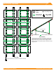

Table Of Contents
- DISCLAIMER
- RATINGS
- MARKINGS
- Checklist
- 1. Build Base
- 2. Connect Substructure
- 3. Place Rails
- 4. SECURE LUGS
- 5. Secure MODULES
- CAMO
- Electrical Diagram
- Diagonal Braces (Optional)
- END CAPS
- Wire Clips
- Splicing Cross Pipe
- Microinverter Kits
- systems using Enphase Microinverters or Sunpower AC Modules
- SYSTEMS USING PHAZR MICROSTORAGE PRODUCTS
- Frameless MODULE Kits
- MODULE COMPATIBILITY
- Module Compatibility
- Module Compatibility

GROUND MOUNT INSTALLATION MANUAL - 8©
2019 IRONRIDGE, INC. VERSION 2.1
ELECTRICAL DIAGRAM
UFO Clamp
Grounding Lug
Min 10 AWG
Copper Wire
Fault Current
Ground Path
Bonding Points Fault Current Ground Path
*Grounding Lugs and wire are not required in systems using
certain Enphase microinverters or certain Sunpower modules.
Equipment grounding is achieved with the Engage cable for
Enphase or the AC module cable system for Sunpower via their
integrated EGC.
*
*
Section View
Plan View
Optional Cross Brace
Only one Grounding Lug required per continuous subarray.
*
Cross Pipe
Rail
Cross Pipe
UFO or
CAMO