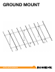
GROUND MOUNT INSTALLATION MANUAL
Contents DISCLAIMER 1 RATINGS 2 MARKINGS 2 CHECKLIST 3 1. BUILD BASE 4 2. CONNECT SUBSTRUCTURE 4 3. PLACE RAILS 5 4. SECURE LUGS 5 5.
RATINGS UL 2703 LISTED #5003225 • Conforms to STD UL 2703 (2015) Standard for Safety First Edition: Mounting Systems, Mounting Devices, Clamping/ Retention Devices, and Ground Lugs for Use with Flat-Plate Photovoltaic Modules and Panels. • Max Overcurrent Protective Device (OCPD) Rating: 25A • Max Module Size: 24ft² • Allowable Design Load Rating: meets minimum requirements of the standard (10 PSF downward, 5 PSF upward, 5 PSF lateral).
CHECKLIST PRE-INSTALLATION IRONRIDGE COMPONENTS ☐☐ Verify module compatibility. See Page 11 for info. ☐☐ Purchase 2” or 3” ASTM A53 Grade B Schedule 40 Pipe, galvanized to a min of ASTM A653 G90 or ASTM A123 G35, or 2” or 3” Allied Mechanical Tubing with Gatorshield or FlowCoat Zinc coating (ASTM A1057).
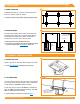
1. Build Base A. MARK LOCATIONS A Establish pier locations. Once grid of pier locations has been set, verify all angles are square. íí Spacing varies with load conditions. Consult engineering specs. B. POSITION PIERS B Excavate the foundation holes. Insert vertical piers into foundation holes, and pour in concrete mixture. Ensure vertical piers are plumb, level, square, and placed in parallel rows. Level the tops so they are even.
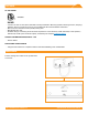
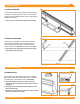
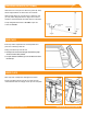
3. Place Rails A. ATTACH HARDWARE A On the ground, attach Rail Connector brackets to rail by sliding 3/8”-16 bonding bolts into side slot. Space out to match pier spacing. With brackets in place, finger tighten flange nuts onto bolts. íí Tape ends of rail, to keep bolts from sliding out while moving. B. FASTEN CONNECTORS Center rails on cross pipes, leaving equal distance on ends. Secure with Rail Connector hardware: 3/8”-16 U-bolts, flange nuts, flat washers, and lock washers.
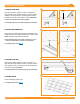
5. SECURE MODULES A. SECURE FIRST END A UFO 80 in-lbs Place first module in position on rails, a minimum of 1” from rail ends. Snap Stopper Sleeves onto UFO. Fasten module to rail using the UFO, ensuring that the UFO is hooked over the top of the module. Torque to 80 in-lbs. íí Ensure rails are square before placing modules. íí Hold Stopper Sleeves on end while torquing to prevent rotation. B. SECURE NEXT MODULES B Place UFO into each rail, placing them flush against first module.
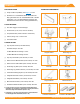
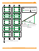
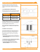
ELECTRICAL DIAGRAM Grounding Lug* UFO Clamp Fault Current Ground Path Min 10 AWG* Copper Wire Cross Pipe Optional Cross Brace Rail Bonding Points Cross Pipe Fault Current Ground Path *Grounding Lugs and Wire are not required in systems using certain Enphase microinverters. Section View Plan View *Only one Grounding Lug required per continuous subarray. © 2018 IRONRIDGE, INC. VERSION 1.
DIAGONAL BRACES (OPTIONAL) Slide sleeve on north pier 2-3” above the ground (6” max). Attach Diagonal Brace to sleeve with 1/2” hardware. Slide second sleeve up on south pier 2-3” below top cap (6” max). Raise Diagonal Brace to align holes in sleeve and brace. Attach hardware and raise sleeve to full extent. Torque Diagonal Brace bolts to 40 ft-lbs. Torque set screws to 15 ft-lbs.
SPLICING CROSS PIPE The following instructions should be followed, when required, to join more than one section of cross pipe together to ensure bonding is maintained throughout the system. A A. ALLIED MECHANICAL TUBING SPLICES Mechanical tube splices shown in the table below shall be of equivalent Allied Flowcoat or Gatorshield zinc coating. Mechanical Tube Size of the Structure Splice Tube Size 2.375” OD, 12 Gauge 2.000” OD, 9 Gauge, Minimum 12” Long 3.500” OD, 8 Gauge 3.
MICROINVERTER KITS Use IronRidge's Microinverter Kit to bond compatible microinverters and power optimizers to the racking system. Insert Microinverter Kit T-bolt into top rail slot. Place compatible microinverter or power optimizer into position and tighten hex nut to 80 in-lbs.
MODULE COMPATIBILITY The Ground Mount System may be used to ground and/or mount a PV module complying with UL 1703 only when the specific module has been evaluated for grounding and/or mounting in compliance with the included instructions. Unless otherwise noted, “xxx” refers to the module power rating and both black and silver frames are included in the certification.
MODULE COMPATIBILITY MAKE MODELS Mitsubishi Modules with 46mm frames and model identifier PV-MYYxxxZZ; where "YY" is LE or JE; and "ZZ" is either HD, HD2, or FB. Motech IM and XS series modules with 40, 45, or 50mm frames. Neo Solar Power Modules with 35mm frames and model identifier D6YxxxZZaa; where "Y" can be M or P; "ZZ" can be B3A, B4A, E3A, E4A, H3A, H4A; and "aa" can be blank, (TF), ME or ME (TF).