™ Elevated Water Seal Technology™ Patented Rail-Free Mounting System for Composition/Asphalt Shingle Roofs RESPECT THE ROOF Installation Manual
Table of Contents Installation Instructions I. Quick Rack Components 1 II. Quick Rack Assemblies 2 III. Array Layout 4 IV. Installing Mounts 5 V. Leveling the Mounts 7 VI. Installing the Clamps 8 VII. Installing the Modules 10 VIII. Wire Management 11 Reference A. General Requirements Ref-1 B. Span Tables, Wind Exposure Category Table, and Rafter Attachment Figures Ref-4 C. Code Compliance Ref-14 D. Approved Modules List Ref-15 E. Grounding Information Ref-17 F.
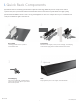
I. Quick Rack Components Quick Rack rail-free mounting system features QRack® technology. With only 3 main components and an optional skirt, the system works with standard module frames and features Quick Mount PV’s high-quality, patented Elevated Water Seal to ensure a long, watertight life on the roof. Components are pre-assembled and ready for installation right out of the box. 1 2 Base Mount Panel Clamp 3 4 Optional Grounding Lug Skirt Featuring Quick Mount PV’s patented Elevated Water Seal.
ITEM NO. II. Quick Rack Assemblies 1 QBLO 2 NOTE: Part quantities are per assembly. For part measurements see pages Ref-20 - Ref-28 for engineering drawings.
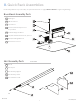
Panel Clamp Assembly Parts A Clamp Base x1 E Hex Nut x1 (x2 for 8") B Panel Clamp (2" or 8") x1 F C Hex Head Cap Screw x1 (x2 for 8") Serrated Flange Hex Nut x1 (x2 for 8") Torque: 13 ft-lbs D Plastic Retainer Ring x1 (2" clamp only) G Clamp Spring (8" clamp only) 2" Panel Clamp Assembly ITEM NO. DESCRIPTION QTY. ITEM NO. 1 CLAMP BASE, QUICK RACK V1.1, 2", 6005A-T5/6061-T6, MILL 1 1 2 PANEL CLAMP, 35MM, QUICK RACK, V1.
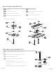
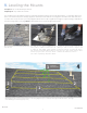
III. Array Layout Using your engineered design, locate array layout on the roof, and determine mount locations. See pages Ref-4 - Ref-14 for span tables, wind exposure categories, cantilevers, and engineering rules. See page Ref-2 for alternative Snow Country Installation Requirements. 1 2 Mark off the locations for the bottom row of mounts. The penetration point for the first row is typically 3" up from the butt of the shingle. Locate rafters that will receive a mount.
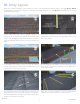
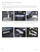
IV. Installing the Mounts Tool Specs: Drill, roofing bar, 1/8" x 6" drill bit, T-30 Torx bit or 1/2" socket, appropriate sealant Screw Embedment Specs: 2.5" minimum embedment into rafter 2 1 3 Use roofing bar to break seals between 1st and Holding the drill square to the rafter, drill 3" deep Fill pilot hole with appropriate sealant. 2nd, and 2nd and 3rd shingle courses. Be sure pilot hole into center of rafter using 1/8" aircraft to remove all nails to allow correct placement extension bit.
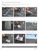
Additional Info Mounts Additional Tips and Information n It is not necessary or advisable to use nails or other fasteners to secure the perimeter of the flashing. n The Base Mount is made to work with standard and high-definition composition/asphalt and wood shingle roofs with 5" to 5-5/8" courses.
V. Leveling the Mounts Tool Specs: 1/2" socket and torque wrench Torque Specs: Top slider bolt = 6 ft-lbs The modules in the Quick Rack system are unified by rigid panel clamps into a single flush surface, so small dips and curves in the roofs surface may not be visually apparent. However, mounts that are close together should be level with each other. To reduce time on the roof, use your own judgment about where a dip is significant enough to require leveling to maintain a smooth looking surface.
VI. Installing the Clamps Tool Specs: 1/2" open end wrench The modules are connected to the base mounts using 2" panel clamps, which can act as both mid clamps or end clamps, see step 3. The 8" panel clamps are used to bridge modules together. 8" panel clamps can either be floating, or attached to a base mount when the rafters align with a module intersection. Panel clamps include integrated grounding pins. See page Ref-17 for grounding information. 2 1 Install all panel clamp assemblies.
Installing the Clamps & Skirt in the First Row Only the front row needs to be aligned and locked down in order to assure a straight and secure skirt and array. All other panel clamps in the following rows do not need to be aligned or locked into the base mounts. See page Ref-2 for alternative Snow Country Installation Requirements. Skirt snap channel 2 1 3 For the first row, clamp must be oriented with Use 1/2" open end wrench on mid-clamp Align first row of clamps using a string line.
VII. Installing the Modules Tool Specs: 1/2" socket and torque wrench Torque Specs: Panel Clamp = 13 ft-lbs 1 Insert the bottom edge of the module frame into the lower clamps. The top of the module sits on the lower portion of the clamp assembly for the row above. 2 Where 2, 3, or 4 modules need to be connected, slide the 8" panel clamp over the module frame. The 8" clamp can either be floating or attached to base mount if the rafters line up. See below for proper module gap and clamp placement.
VIII. Wire Management Tool Specs: Wire clips, flat head screw driver, 5/16" socket and torque wrench Torque Specs: Grounding lug bolt = 35 in-lbs, grounding lug set screw - see below 1 2 Complete wire management on a row-by-row Before connecting the modules together, be sure basis. With a two man crew, wire management to position one of the PV wires out to serve as the and clamp tightening can be done at the same homerun connection. time.
Additional Info Wire Management Wire Configuration and Clip Placement Suggested Landscape Configuration Suggested Portrait Configuration Straight or Combination Wire Clips 90° or Combination Wire Clips Junction Box * To prevent any contact with the roof all wires must be managed by wire clips. BI 7.2.
Additional Info Wire Management Junction Box Suggested Micro-Inverter Landscape Configuration Trunk cable termination cap Trunk Cable Bracket Trunk Clip / Bracket Suggested Micro-Inverter Portrait Configuration Nine DCS 1307PV Wire TrunkFastener Cable Clip Heyco® Sunrunner® 90° Trunk Cable Clip 90° Micro Micro Inverter Inverter Trunk Cable Cable PV Wire Clips Junction Box Follow module level electronics instructions for mounting.
Additional Info Wire Management Wire Clip Recommendations Rail-free systems are dependent on wire management clips that hold securely to both the wires and the module frames. After extensive testing, we recommend the following products with this system.
Reference The Span Tables, Wind Exposure Category Table, and Rafter Attachment Pattern Figures beginning on page Ref-4 are subject to the requirements shown in the table footnotes and to the following criteria. See Quick Rack V1.1-2 Base Mount Code Compliance Report dated 1-03-2017 by Mar Structural Design if additional information is required. Region and Site n The roof is not in a special topographic region subject to wind speed-up effects, such as near or at the crest of a tall ridge or hill (i.e.
Installation Specifics, cont'd Each Quick Rack base mount is fastened to the roof rafter with one 5/16" nominal diameter structural screw, defined as either a 5/16" nominal diameter GRK RSS screw with Climatek coating or a 5/16" nominal diameter QMPV Dual-Drive screw, each pre-drilled with an 1/8" pilot hole to prevent splitting. The structural screw shall be embedded at least 2.5" into the roof rafter.
Snow Country Installation Requirements, cont'd n n BI 7.2.3-28 • At any bottom row of mounts, clamps shall be installed on top sliders so that the center of the machine bolt into the top slider is 1.5" upslope from the center of the top slider. • For subsequent rows of mounts, clamps shall be installed so that the center of the machine bolt into the top slider shall be installed no more than 1.5" upslope or 1.0" downslope from the center of the top slider.
BI 7.2.
110 mph 115 mph 120 mph 130 mph 140 mph 150 mph 85 mph 90 mph 95 mph 100 mph 110 mph 120 mph Roof Pitch 2:12 to 6:12 7:12 to 12:12 2:12 to 6:12 7:12 to 12:12 2:12 to 6:12 7:12 to 12:12 2:12 to 6:12 7:12 to 12:12 2:12 to 6:12 7:12 to 12:12 2:12 to 6:12 7:12 to 12:12 24'' 21'' 24'' 21'' 24'' 14'' 21'' 14'' 14'' 7'' 14'' 7'' 24'' 14'' 21'' 14'' 21'' 14'' 14'' 7'' 14'' 7'' 7'' 7'' 24'' 24'' 24'' 24'' 24'' 24'' 24'' 21'' 24'' 14'' 21'' 14'' 24'' 22'' 24'' 22'' 24'' 22'' 22'' 15'' 22'' 15'' 15'' 15
(Strength Level) 110 mph 115 mph 120 mph 130 mph 140 mph 150 mph (Service Level) 85 mph 90 mph 95 mph 100 mph 110 mph 120 mph Roof Pitch 2:12 to 6:12 7:12 to 12:12 2:12 to 6:12 7:12 to 12:12 2:12 to 6:12 7:12 to 12:12 2:12 to 6:12 7:12 to 12:12 2:12 to 6:12 7:12 to 12:12 2:12 to 6:12 7:12 to 12:12 C 48'' 32'' 48'' 32'' 32'' 32'' 32'' 24'' 32'' 24'' 24'' 24'' B 48'' 48'' 48'' 48'' 48'' 32'' 48'' 32'' 32'' 32'' 32'' 32'' 0 - 15 psf D 16'' 32'' 24'' 32'' 24'' 24'' 24'' 24'' 32'' 32'' 32'' 3
115 mph 120 mph 130 mph 140 mph 150 mph 90 mph 95 mph 100 mph 110 mph 120 mph Roof Pitch 2:12 to 6:12 7:12 to 12:12 2:12 to 6:12 7:12 to 12:12 2:12 to 6:12 7:12 to 12:12 2:12 to 6:12 7:12 to 12:12 2:12 to 6:12 7:12 to 12:12 2:12 to 6:12 7:12 to 12:12 32'' 24'' 32'' 24'' 24'' 24'' 24'' 16'' 32'' 22'' 15'' 22'' 15'' 15'' 15'' 15'' 12'' 15'' 12'' 12'' 12'' 15'' 15'' 15'' 15'' 15'' 12'' 15'' 12'' 12'' 12'' 12'' 12'' 14'' 14'' 14'' 14'' 14'' 7'' 14'' 7'' 7'' 7'' 7'' 7'' 14'' 7'' 14'' 7'' 7'' 7'' 7
Ref-8 150 mph 140 mph 130 mph 115 mph 110 mph 150 mph 140 mph 130 mph 115 mph 110 mph 150 mph 140 mph 130 mph 115 mph 110 mph ASCE 7-10 Wind Speed Roof Pitch Flat to 6:12 7:12 to 12:12 Flat to 6:12 7:12 to 12:12 Flat to 6:12 7:12 to 12:12 Flat to 6:12 7:12 to 12:12 Flat to 6:12 7:12 to 12:12 Flat to 6:12 7:12 to 12:12 Flat to 6:12 7:12 to 12:12 Flat to 6:12 7:12 to 12:12 Flat to 6:12 7:12 to 12:12 Flat to 6:12 7:12 to 12:12 Flat to 6:12 7:12 to 12:12 Flat to 6:12 7:12 to 12:12 Flat to 6:12 7
Clamp and Top Slider Allowable Positions Figure 2B Reference GRO U Land ND SNO W LO scap e Portr A ait M Mode: 0- D: ode: 2 0-15 0 PSF PSF BI 7.2.
Cantilever Reference Figure 4 This figure references tables on pages Ref-3 - Ref-7 . Reference BI 7.2.
Rafter Attachment Pattern Figure 7 Reference BI 7.2.
Rafter Attachment Pattern Figure 8 Reference BI 7.2.
Rafter Attachment Pattern Figure 9 Reference BI 7.2.
Rafter Attachment Pattern Figure 10 Reference C. Code Compliance n 2015 International Building Code compliant n 2016 California Building Code compliant n ASCE 7-10 Minimum Design Loads for Buildings and Other Structures compliant n Conforms to UL STD 2703, ETL listed by Intertek, see page Ref-15 for compliance requirements. BI 7.2.
D. Approved Modules List Maximum Allowable Module Cantilever Model Dimensions Modules load tested at 50 PSF downward, 35 PSF upward, 23.
Evaluated and Approved Modules for use with Quick Rack per ANSI/UL 2703 Edition 1 Maximum Allowable Module Cantilever Model Dimensions Reference Modules load tested at 50 PSF downward, 35 PSF upward, 23.
E. Grounding Information Grounding lug must be visible to inspectors from the perimeter of the array. To avoid breaking the bonding path during routine maintenance please use one of the following 2 options: n By replacing base mount cap screw with a second Ilsco GBL-4DBT grounding lug in an undisturbed portion of the array and running the properly sized bare copper wire for over current protection back to the ground fault circuit. Install grounding lug per page 11 requirements.
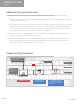
F. Grounding Path Diagrams Reference Standard Grounding Path Diagram Legend Bonding Pin Bonding Path X Ilsco GBL-4DBT Grounding Lug Location Grounding Lug Grounding Wire X BI 7.2.
Reference Micro Inverter Grounding Path Diagram Legend Bonding Path Trunk Cable Bracket Trunk Clip / Bracket Nine DCS 1307PV Wire Clip TrunkFastener Cable Clip Heyco® Sunrunner® 90° Trunk Cable Clip 90° Micro Micro Inverter Inverter Trunk Cable Cable PV Wire Clips Ground BI 7.2.
Enphase® Micro-inverter Grounding Specifics Reference In a standard landscape array, the Enphase inverter bracket will be installed approximately 7" in from the edge of the module. Place the bracket clamp over the edge of the module frame. With the cap screw threaded into the channel on the bracket, slide the Enphase inverter on top of the bracket with the cap screw in the middle channel on the inverter.
G.
H. Engineering Drawings Reference 6 ITEM NO. DESCRIPTION QTY. 1 FLASHING, 9" X 12" X .
Torque = 13 ft-lbs DESCRIPTION QTY. 1 CLAMP BASE, QUICK RACK V1.1, 2", 6005A-T5/6061-T6, MILL 1 2 PANEL CLAMP, 33MM, QUICK RACK, V1.1, 2", 6005AT5/6005A-T61/6061-T6, BRONZE 1 3 CAP SCREW, HEX HEAD, 5/16"-18 X 2" UNC-2A, 18-8 SS 1 4 NUT, JAM, HEX, 5/16-18, UNC-2B, 18-8 SS 1 5 RETAINER RING, EXTERNAL PUSH-ON, 5/16", CIRCULAR, PLASTIC 1 6 NUT, SERRATED FLANGE, HEX, 5/16"-18, UNC-2B, 18-8 SS 1 2 5 1 4 3 TITLE: QMQR-CP33.2: QUICK RACK V1.
Reference ITEM NO. DESCRIPTION QTY. 1 CLAMP BASE, QUICK RACK V1.1, 8", 6005A-T5/6061-T6, MILL 1 2 PANEL CLAMP, 33MM, QUICK RACK, V1.1, 8", 6005A-T5/6005AT61/6061-T6, BRONZE 1 3 CAP SCREW, HEX HEAD, 5/16"-18 X 2" UNC-2A, 18-8 SS 2 4 NUT, JAM, HEX, 5/16-18, UNC-2B, 18-8 SS 2 5 NUT, SERRATED FLANGE, HEX, 5/16"-18, UNC-2B, 18-8 SS 2 6 CLAMP SPRING, 8", QUICK RACK, V1.1, NYLON 66, BLACK 1 Torque = 13 ft-lbs 5 2 4 6 1 3 TITLE: QMQR-CP33.8: QUICK RACK V1.
Torque = 13 ft-lbs 5 DESCRIPTION QTY. 1 CLAMP BASE, QUICK RACK V1.1, 2", 6005A-T5/6061-T6, MILL 1 2 PANEL CLAMP, 35MM, QUICK RACK, V1.1, 2", 6005AT5/6005A-T61/6061-T6, BRONZE 1 3 CAP SCREW, HEX HEAD, 5/16"-18 X 2" UNC-2A, 18-8 SS 1 4 NUT, JAM, HEX, 5/16-18, UNC-2B, 18-8 SS 1 5 RETAINER RING, EXTERNAL PUSH-ON, 5/16", CIRCULAR, PLASTIC 1 6 NUT, SERRATED FLANGE, HEX, 5/16"-18, UNC-2B, 18-8 SS 1 2 1 4 3 TITLE: QMQR-CP35.2: QUICK RACK V1.
Reference ITEM NO. DESCRIPTION QTY. 1 CLAMP BASE, QUICK RACK V1.1, 8", 6005A-T5/6061-T6, MILL 1 2 PANEL CLAMP, 35MM, QUICK RACK, V1.1, 8", 6005A-T5/6005AT61/6061-T6, BRONZE 1 3 CAP SCREW, HEX HEAD, 5/16"-18 X 2" UNC-2A, 18-8 SS 2 4 NUT, JAM, HEX, 5/16-18, UNC-2B, 18-8 SS 2 5 NUT, SERRATED FLANGE, HEX, 5/16"-18, UNC-2B, 18-8 SS 2 6 CLAMP SPRING, 8 INCH, QUICK RACK, V1.1, NYLON 66, BLACK 1 Torque = 13 ft-lbs 5 2 6 4 1 3 TITLE: QMQR-CP35.8: QUICK RACK V1.
DESCRIPTION QTY. 1 CLAMP BASE, QUICK RACK V1.1, 2", 6005A-T5/6061-T6, MILL 1 2 PANEL CLAMP, 40MM, QUICK RACK, V1.1, 2", 6005AT5/6005A-T61/6061-T6, BRONZE 1 3 CAP SCREW, HEX HEAD, 5/16"-18 X 2" UNC-2A, 18-8 SS 1 4 NUT, JAM, HEX, 5/16-18, UNC-2B, 18-8 SS 1 5 RETAINER RING, EXTERNAL PUSH-ON, 5/16", CIRCULAR, PLASTIC 1 6 NUT, SERRATED FLANGE, HEX, 5/16"-18, UNC-2B, 18-8 SS 1 6 Torque = 13 ft-lbs 5 2 4 1 3 TITLE: QMQR-CP40.2: QUICK RACK V1.
Reference Torque = 13 ft-lbs 5 2 ITEM NO. DESCRIPTION QTY. 1 CLAMP BASE, QUICK RACK V1.1, 8", 6005A-T5/6061-T6, MILL 1 2 PANEL CLAMP, 40MM, QUICK RACK, V1.1, 8", 6005AT5/6005A-T61/6061-T6, BRONZE 1 3 CAP SCREW, HEX HEAD, 5/16"-18 X 2" UNC-2A, 18-8 SS 2 4 NUT, JAM, HEX, 5/16-18, UNC-2B, 18-8 SS 2 5 NUT, SERRATED FLANGE, HEX, 5/16"-18, UNC-2B, 18-8 SS 2 6 CLAMP SPRING, 8 INCH, QUICK RACK, V1.1, NYLON 66, BLACK 1 6 4 1 3 TITLE: QMQR-CP40.8: QUICK RACK V1.
'(6&5,37,21 47< 6.,57 48,&. 5$&. 9 7 %521=( 6.,57 &/,3 48,&. 5$&. 9 7 0,// ,7(0 $9$,/$%/( ,1 $1' /(1*7+6 $77$&+ 6.,57 &/,36 $6 6+2:1 '(7$,/ % 6&$/( % 7,7/( 4045 6/ 6.,57 $66(0%/< 48,&. 5$&. 9 /$1'6&$3( 81/(66 27+(5:,6( 63(&,),(' 35235,(7$5< $1' &21),'(17,$/ 7+( ,1)250$7,21 &217$,1(' ,1 7+,6 '5$:,1* ,6 7+( 62/( 3523(57< 2) 48,&.
,7(0 12 Reference '(6&5,37,21 47< (1' &$3 6.,57 5,*+7 48,&. 5$&. 9 + %521=( (1' &$3 6.,57 /()7 48,&. 5$&. 9 + %521=( 6&5(: 6+((7 0(7$/ ; 66 %/$&. 0$5.27( 7,7/( 4045 6& (1' &$3 6.,57 48,&. 5$&. 9 81/(66 27+(5:,6( 63(&,),(' 35235,(7$5< $1' &21),'(17,$/ 7+( ,1)250$7,21 &217$,1(' ,1 7+,6 '5$:,1* ,6 7+( 62/( 3523(57< 2) 48,&.
Notes BI 7.2.
RESPECT THE ROOF 925-478-8269 | 2700 Mitchell Dr. | Walnut Creek, CA 94598 www.quickmountpv.com | tech@quickmountpv.com UL STD 2703 BI 7.2.3-28 Made in USA ©2016 by Quick Mount PV. All rights reserved.