GROUND MOUNT INSTALLATION MANUAL
CONTeNTS DISCLAIMeR CHeCKLIST 1. BUILD BASe 2. CONNeCT SUBSTRUCTURe 3. PLACe RAILS 4. SeCURe LUGS 5. CLAMP MODULeS DIAGONAL BRACeS (OPTIONAL) UNDeR CLAMPS (OPTIONAL) eND CAPS (OPTIONAL) WIRe CLIPS (OPTIONAL) WARRANTY 1 2 3 3 4 4 5 6 6 6 6 7 DISCLAIMeR This manual describes the proper installation procedures and provides necessary standards required for product reliability and warranty.
CHeCKLIST PRe-INSTALLATION PRIMARY COMPONeNTS ☐ Verify module compatibility with Ground Mount. 204 & 60 in-lbs ☐ Purchase 2” or 3” schedule 40 steel pipe (ASTM A53 Grade B) or mechanical tubing (Allied Flo-Coat and Gatorshield) for structure. ☐ Verify that needed components have been obtained. Contact your local distributor for any additional parts.
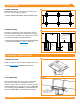
1. BUILD BASe A. MARK LOCATIONS Establish pier locations. Once grid of pier locations has been set, verify all angles are square. A ☑ Spacing varies with load conditions. Consult engineering specs. B. POSITION PIeRS B Excavate for foundations, insert vertical piers, and pour concrete foundations. Make sure vertical piers are plumb, level, and square, in parallel rows, evening tops with level. Level Tops ☑ For concrete foundations, brace piers until cured.
3. PLACe RAILS A. ATTACH HARDWARe A On ground, attach Rail Connector bracket to rail by sliding 3/8”-16 bolts into side slot. Space out to match pier spacing. With bracket in place, finger tighten flange nuts onto bolts. Repeat for remaining Rail Connectors. ☑ If using Mid Clamps with hex bolts, slide provided 1/4”-20 bolts into top slot of rails at this time. Space bolts for panel spacing. ☑ Tape ends of rail, to keep bolts from sliding out while moving. B.
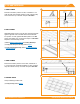
5. CLAMP MODULeS A. eND CLAMPS A Torque to 84 in-lbs Place first module in position on rails, a minimum of 1.5” from rail ends. Secure End Clamps on rails, ensuring they are hooked over top of module. Torque to 84 in-lbs. B. MID CLAMPS B Slide Mid Clamp T-bolts in top rail slots, placing them flush against opposite side of module. Place second module into position on rails, against Mid Clamp bolts. Put a Mid Clamp, then flange nut, on each bolt. Torque to 120 in-lbs. Repeat for each following module.
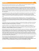
DIAGONAL BRACeS (OPTIONAL) Slide sleeve on north pier, 2-3” above the ground. Attach Diagonal Brace to sleeve with 1/2” hardware. Slide second sleeve on south pier, raising Diagonal Brace to align holes in sleeve and brace. Attach hardware and raise sleeve to full extent. Torque Diagonal Brace assembly to 480 in-lbs. Torque Hardware to 480 in-lbs Sleeve Diagonal Brace South Pier North Pier UNDeR CLAMPS (OPTIONAL) Slide Under Clamp into side rail slot.
WARRANTY Effective for Products manufactured after April 1st, 2012, IronRidge provides the following warranties, for Products installed properly and used for the purpose for which the Products are designed: (a) Products with finishes (ie excluding without limitation Products that are mill finished) shall be free of visible defects, peeling, or cracking, under normal atmospheric conditions, for a period of three years from the earlier of (i) the date of complete installation of the Product or (ii) 30 days af