
Brochure


Page 9
Parts Catalog
2016 v1.85
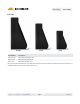
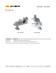
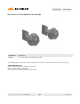
Rail Assembly
support | ironridge.com | (800) 227-9523
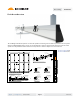
Calculating Rail Length
Calculate the row lengths as follows:
1. Add module widths
2. Add width of mid clamps between modules
3. Add allowances for end clamps on ends of rail
Depending on the clamp selected for the system, the clearance values will dier slightly.
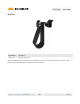
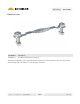
Grounding Mid Clamps UFO
Mid Clamp 0.25” 0.375”
End Clamp 1.5” 1.0”
For example, to mount ve modules that are each 40” wide (in portrait), the row length is calculated as follows:
Using Grounding Mid Clamps Using UFO
1. Add module widths 5 x 40” = 200”
2. Add width of mid clamps between modules 4 x 0.25” = 1” 4 x 0.375” = 1.5”
3. Add allowances for end clamps 2 x 1.5” = 3” 2 x 1” = 2
Total length of row 204” 203.5”
Two 17’ rails will be required to mount this row of ve modules.
IronRidge stock rail lengths: 11’, 14’, 17’. Custom lengths available via special order. Contact IronRidge Customer
Service for additional details at 800-227-9523, or support@ironridge.com.
Mm Inches End Clamp Grounding Mid Clamp
31.0 - 32.5 1.22 - 1.28 29-7000-125 RS-GD-MCL-200
32.5 - 33.5 1.28 - 1.32 29-7000-130 RS-GD-MCL-200
33.3 - 34.8 1.31 - 1.37 29-7000-134 RS-GD-MCL-200
34.8 - 36.8 1.37 - 1.45 29-7000-224 RS-GD-MCL-225
37.6 - 38.6 1.48 - 1.52 29-7000-150 RS-GD-MCL-225
39.0 - 41.0 1.53 - 1.61 29-7000-157 RS-GD-MCL-225
41.1 - 42.7 1.62 - 1.68 29-7000-165 RS-GD-MCL-250
42.7 - 44.2 1.68 - 1.74 29-7000-171 RS-GD-MCL-250
45.0 - 47.0 1.77 - 1.85 29-7000-214 RS-GD-MCL-250
46.7 - 48.3 1.84 - 1.90 29-7000-187 RS-GD-MCL-275
49.0 - 51.1 1.93 - 2.01 29-7000-204 RS-GD-MCL-275
Module Frame Height Part Numbers
Grounding Mid Clamp Sizing Chart
Clamp size depends on module frame height. Use table below to determine which clamp is required for your project.