
Product Manual


Page 7 of 11
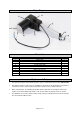
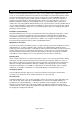
Part#
Description
Quantity
1
Motor shell
1
2
Screw 4*16
3
3
Round tube
1
4
Tear drop type tube
1
5
Plastic cover
1
6
Fixed mount
1
7
Bottom cap of motor
1
8
Screw with washer M5
1
9
Coach bolt M4*7
1
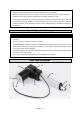
Assembly Instructions
1. Ensure that the extension tube is in the "lowest position". The term "lowest position" refers to the
position in which there is no further movement toward the DC motor while the actuator is powered
on (refer to illustration below).
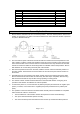
2. The front and end joints of the linear actuator should be mounted onto two fixed positions on the
main chassis. Locations of these fixed positions should be chosen according to the stroke length
of the linear actuator. Users must use caution to ensure that the two-way movement of the linear
actuator is smooth and within the stroke length after it’s installed onto the fixed positions. Ensure
that obstacles do not exist along the travel path of the actuator.
3. After the fixed positions have been selected, install the fixtures onto these selected positions of
the main chassis. These fixtures are used to attach the front and end joints of linear actuator to
the chassis.
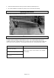
4. Assemble the front and end joints of the linear actuator onto the two fixtures using fixture bolts.
Ensure that the fixture bolts are able to rotate freely after this step is completed, while ensuring
that the fixture bolts will not drop off either during operating or resting period.
5. The chassis of linear actuator should be attached in the horizontal direction if it is going to be
operated in this direction and likewise for vertical operation.
6. To extend the piston rod, connect blue wire to positive post (blue) and black wire to negative post
(brown). To retract, connect blue wire to negative post (brown) and black wire to positive post
(blue).
7. The operation of the linear actuator should be tested manually after the installation is completed.
Users should use caution to ensure that:
• The travel distance of the actuator matches the requirement of the structural design.
• The up and low limit switches operate normally.
• The motor should stop when the extension tube reaches up and low limit switch positions.