8 Inch Heavy-Duty Benchtop Grinder Owner’s Manual WARNING: Read carefully and understand all ASSEMBLY AND OPERATION INSTRUCTIONS before operating. Failure to follow the safety rules and other basic safety precautions may result in serious personal injury.
® Thank you very much for choosing an Ironton product! For future reference, please complete the owner’s record below: Serial Number/Lot Date Code: ________________________________ Purchase Date: ____________________________________________ Save the receipt, warranty, and this manual. It is important that you read the entire manual to become familiar with this product before you begin using it. This benchtop grinder is designed for certain applications only.
Table of Contents Intended Use .......................................................................................................................................... 4 Packaging Contents .............................................................................................................................. 4 Technical Specifications ...................................................................................................................... 4 Important Safety Information .................
Intended Use This Ironton 8 Inch Heavy-Duty Benchtop Grinder is ideal for use in sharpening chisels, axes, and other wood-cutting tools. It is also useful for repairing tips on screwdrivers and drill bits or for removing excess metal burrs from pieces of cut metal. Packaging Contents Bench Grinder 2 Eye Shields Hardware Bag Owner’s Manual 2 Tool Rests Technical Specifications Property Rate Motor Speed Wheel Size Arbor Weight Specification 110V/60 Hz 3/4 HP 3600 RPM 8 in. x 1 in.
Cluttered, wet, or dark work areas can result in injury. Using the product in confined work areas may put you dangerously close to cutting tools and rotating parts. Do not use the product where there is a risk of causing a fire or an explosion; e.g., in the presence of flammable liquids, gases, or dust. The product can create sparks, which may ignite the flammable liquids, gases, or dust. Do not allow the product to come into contact with an electrical source.
the power switch is dangerous and must be repaired by an authorized service representative before using. Disconnect the power/air supply from the product and place the switch in the locked or off position before making any adjustments, changing accessories, or storing the tool. Such preventive safety measures reduce the risk of starting the tool accidentally. Store the bench grinder when it is not in use. Store it in a dry, secure place out of the reach of children.
and grounded in accordance with ALL local codes and ordinances. DO NOT MODIFY THE PROVIDED PLUG. If it will not fit the receptacle, have the proper receptacle installed by a qualified electrician. CHECK with a qualified electrician or service person if you do not completely understand the grounding instructions, or if you are not sure the tool is properly grounded. Grounded Tools: Tools with 3-Prong Plugs Tools marked with Grounding Required have a 3-wire cord and 3-prong grounding plug.
Grounded tools require a 3-wire extension cord. Double Insulated tools can use either a 2- or 3wire extension cord. As the distance from the supply outlet increases, you must use a heavier gauge extension cord. Using extension cords with inadequately sized wire causes a serious drop in voltage, resulting in loss of power and possible tool damage. The smaller the wire’s gauge number, the greater the capacity of the cord. For example, a 14gauge cord can carry a higher current than a 16-gauge cord.
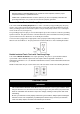
Mounting the Grinder to the Workbench Before attempting to use this grinder, it must be properly mounted to a workbench or grinding stand. Note: Bench grinders vibrate. Grinder movement during high-speed rotation may cause injury to the operator or damage to the workpiece. Mount the grinder securely to a sturdy workbench or grinding stand. 1. Position the grinder on the workbench. Mark the workbench through the two mounting holes located in the grinder base (see illustration below). 2.
Eye Shield Installation Note: Eye shields must be installed before operating the bench grinder. 1. Mount the left and right shield rods to the inside of the wheel guards using hex bolts. 2. Once the shield rods are firmly in place, slide the shield bracket onto the shield rod. Tighten the carriage bolt, leaving it loose enough to allow the safety shield to be raised and lowered easily. Note: The eye shield should move freely when being adjusted but stay in place when the locking knob is tightened.
Operating Instructions ⚠WARNING Always wear eye protection. Only use accessories rated at least equal to the maximum speed marked on the tool. Do not modify the tool in any way. Do not wear gloves, jewelry, or loose clothing. Do not use a cracked or chipped grinding wheel. Bolt down bench grinder before using. Do not use in the rain or in a damp location. Never reach to pick up a workpiece, a piece of scrap, or anything else that is in or near the grinding path of the wheel.
Switch Grinding 1. Allow the bench grinder to come up to full speed before touching the wheel. 2. Bring the workpiece up to the wheel, gently and without jarring. Use the tool rest to support the workpiece as you steadily move the workpiece to the wheel. 3. Keep the workpiece moving across the face of the wheel so that the grinding wheel wears evenly from side to side. Note: The workpiece will quickly become heated. Frequently submerge the workpiece in water.
Maintain the bench grinder by adopting a program of conscientious repair and maintenance in accordance with the following recommended procedures. It is recommended that the general condition of any tool be examined before it is used. Keep handles dry, clean, and free from oil and grease. The following chart is based on a normal operation schedule. Maintenance Interval Maintenance Point 1. 2. 3. 4. 5. Daily before operating Examine the general condition of the bench grinder. Check the power cord.
Failure Unit slows when operating. Wavy condition on surface of workpiece. Lines on surface of workpiece. Burning spots or cracks in the workpiece. Wheel dulls quickly or grit falls off. Wheel clogs and workpiece shows burn marks. Possible Cause Corrective Action Incorrect fuses or circuit breakers in power line. Have a qualified technician repair unit. Motor overload. Reduce the load on the motor. Feed rate is too great.
Parts Diagram Page 15 of 19
Parts List Part Number 1 2 3 4 5 6 7 8 9 10 11 12 13 14 15 16 17 18 19 20 21 22 23 24 25 26 27 28 29 30 31 32 33 34 35 36 37 38 39 40 41 42 43 44 45 46 47 48 49 50 51 52 Part Description Philips Screw (Zinc Coating) Philips Screw (Black) Left Wheel Guard Cover Hex Nut Type "I" (Zinc Coating) Wheel Flange 36#Wheel, P200 x 25 x 15.
Part Number 53 54 55 56 57 58 59 60 61 62 63 64 65 66 Part Description Right Work Rest Right Wheel Guard 60# Wheel, P200 x 25 x 15.88 Hex Nut Type "I" (Zinc Coating) Right Wheel Guard Cover Base Hex Nut Type "I" (Zinc Coating) Capacitor Capacitor Support Tool Storage Bottom Cover Tool Storage Rubber Foot Big Flat Washer (Zinc Coating) Lamp Quantity 1 1 1 1 1 1 1 1 1 1 1 4 4 2 Replacement Parts For replacement parts and technical questions, please call Customer Service at 1-800-222-5381.
Limited Warranty Northern Tool and Equipment Company, Inc. ("We'' or ''Us'') warrants to the original purchaser only (''You'' or ''Your'') that the Ironton product purchased will be free from material defects in both materials and workmanship, normal wear and tear excepted, for a period of one year from date of purchase. The foregoing warranty is valid only if the installation and use of the product is strictly in accordance with product instructions.
Distributed by: Northern Tool & Equipment Company, Inc. Burnsville, Minnesota 55306 www.northerntool.