250 LB. CAPACITY MECHANICAL WHEEL DOLLY OWNER'S MANUAL WARNING: Read carefully and understand all ASSEMBLY AND OPERATION INSTRUCTIONS before operating. Failure to follow the safety rules and other basic safety precautions may result in serious personal injury.
Thank you very much for choosing a IRONTON product. For future reference, please complete the owner's record below: Model: _______________ Purchase Date: _______________ Save the receipt, warranty and these instructions. It is important that you read the entire manual to become familiar with this product before you begin using it. This machine is designed for certain applications only. The distributor cannot be responsible for issues arising from modification.
Safety Warnings and Precautions WARNING: When using product, basic safety precautions should always be followed to reduce the risk of personal injury and damage to equipment. Read all instructions before using this product! 1. Keep work area clean. Cluttered areas invite injuries. 2. Observe work area conditions. Do not use machines or power tools in damp or wet locations. Don’t expose to rain. Keep work area well lighted. 3. Keep children away. Children must never be allowed in the work area. 4.
11. Replacement parts and accessories. When servicing, use only identical replacement parts. Use of any other parts will void the warranty. 12. Do not operate product if under the influence of alcohol or drugs. Read warning labels if taking prescription medicine to determine if your judgment or reflexes are impaired while taking drugs. If there is any doubt, do not operate the product.
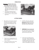
OPERATION IMPORTANT! BEFORE FIRST USE: Lock Pin (17) • Thoroughly lubricate and test the Wheel Dolly for proper operation. 1. Position Dolly in front of tire and slide Latch (24) to right. Lift Lock Pin (17) and rotate counterclockwise until tab faces away from Pedal Arm (19). See Figure 1. 2. Place hands on Rollers (8) and spread apart to tire width required. 3. Pedal Arm (19) Tab Roll Dolly forward, centering Rollers against tire. Figure 1 Latch (24) LIfTING WHEEL 1. Slide Latch to left.
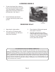
LOWERING WHEELS 1. To lower the Wheel Dolly, slide the Latch counterclockwise (to the right). Turn Tab clockwise, making sure it aligns with the channel at the end of the Pedal Arm. See Figure 3. Tab Figure 3 Channel 2. Push Pedal down and release. Continue until tire fully rests on the ground. REMOVING DOLLY Latch (24) 1. Keep Latch in right position. 3. 2. Lift Lock Pin (17) and turn right (counterclockwise) until Tab faces away from Pedal Arm.
PARTS LIST AND ASSEMBLY DIAGRAM Part 1 2 3 4 5 6 7 8 9 10 11 12 13 Description Nut M12 Spring Washer 12 Caster Assembly Rod Assembly Lock Nut M12 Bolt M12*55 Washer Roller Assembly Outer Body Axle Assembly Inner Body Axle Assembly Screw M6*10 Big Washer 6 Carry Head Assembly Q’ty 4 4 4 2 3 2 4 2 1 1 1 2 1 Part 14 15 16 17 18 19 20 21 22 23 24 25 26 Description Spring Ring Bushing Spring Lock Pin Spring Pin 4*16 Pedal Arm Support Plate Retaining Ring 8 Axis Lock Nut M6 Latch Retaining Spring Bolt M12*8
limited 90 Day Warranty Northern Tool + Equipment Co., Inc. makes every effort to assure that its products meet high quality and durability standards, and warrants to the original purchaser that this product is free from defects in materials and workmanship for the period of 90 days from the date of purchase.