
Product Manual


For technical questions, please call
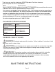
PARTS LIST AND ASSEMBLY DIAGRAM
Part Description Q’ty
1 Nut M12 4
2 Spring Washer 12 4
3 Caster Assembly 4
4 Rod Assembly 2
5 Lock Nut M12 3
6 Bolt M12*55 2
7 Washer 4
8 Roller Assembly 2
9 Outer Body Axle Assembly 1
10 Inner Body Axle Assembly 1
11 Screw M6*10 1
12 Big Washer 6 2
13 Carry Head Assembly 1
Part Description Q’ty
14 Spring Ring 1
15 Bushing 1
16 Spring 1
17 Lock Pin 1
18 Spring Pin 4*16 1
19 Pedal Arm 1
20 Support Plate 1
21 Retaining Ring 8 2
22 Axis 1
23 Lock Nut M6 1
24 Latch 1
25 Retaining Spring 1
26 Bolt M12*80 1
Note: Some parts are listed and shown for illustration purposes only and are not avail-
able individually as replacement parts.
1-800-222-5381.
Page 7