
User Manual
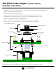

Socket
Top Assembly
Compression Screw
Compression plate
BGA Package
Z-Axis Elastomer
Socket Base Assembly
Machine Flat Head Screw
Target PCB with SMT pads
Socket Lid
Probe Assembly
Oval Head Screw
Hex nut
GHZ BGA Probe Adapter (surface mount)
Assembly Instructions
© 2002 IRONWOOD ELECTRONICS, INC.
Tele: (800) 404-0204
www.ironwoodelectronics.com
1. Reflow Socket Base assembly to the target PCB (as per BGA surface mount foot soldering instructions).
2. Place the square piece of elastomer provided into the socket base (Note orientation mark on the socket base and the elastomer).
3.
Adjust the elastomer to sit into the Socket Base cavity.
4. Remove hex nuts from the bottom of Probe assembly.
5. Place probe assembly into the socket and assemble with the hardware provided (four 0-80 machine flat head screws).
6. Place BGA package (solder ball side down) into the socket on the probe assembly. NOTE: BGA orientation is critical.
7. Place the compession plate (if required*) on top of the BGA package.
8. Place the socket top assembly through oval head screws on to the socket using the key hole slot and slide.
9. Turn the compression screw clockwise, until it makes contact with the compression plate or the BGA package.
10. Turn an additional quarter-turn.
*Ironwood Electronics technical staff will determine (from your package spec) if a compression or alignment plate is required
Filename: FBD.mcd, Rev A, 12/19/02, ELS