
assembly instruction using four set screws Owner's manual
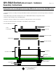

Socket Base
Target PCB with SMT pads
Socket
Top Assembly
Set Screw (x4)
Compression plate
BGA Package
Angle wire elastomer
Socket Lid
Round head Screw
Dowel pin
Socket Base Assembly
Backing Plate
(not necessary for
some sockets)
Hex Nut
Nylon Washer
GHZ BGA Socket (direct mount - hardware)
Assembly Instructions
© 2002 IRONWOOD ELECTRONICS, INC.
Tele: (800) 404-0204
www.ironwoodelectronics.com
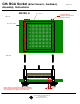
1. Install the socket base assembly on the target PCB with the hardware (round head 0-80 screws and nuts) provided (see Detail A for
orientation).
2. Place BGA package (solder ball side down) into the socket. NOTE: BGA orientation on target PCB is critical.
3. Place the compession plate on top of the BGA package.
4. Install the socket top assembly on to the socket base assembly and swivel to lock into the position.
5. Turn the set screw (x4) clockwise, until it makes contact with the compression plate.
6. Turn an additional 3 to 5 turns.
Tooling holes have to be designed into the target PCB for this version of the GHz BGA socket
Filename: GCI.mcd, Rev A, 6/25/02, IP
Page 1 of 2