
Assembly Instructions User guide

Page 1 of 4 GFI.doc, Rev.A, Created by E Smolentseva, 10/22/03
Tel: (800) 404-0204
www.ironwoodelectronics.com
Socket Assembly:
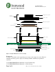
Refer to figure 1 for graphical illustrations.
1. Install the socket base assembly on the target PCB with the hardware, socket base screws
and nuts, provided. Because of the asymmetrical location of the tooling holes, the socket
can be assembled only one way.
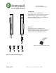
2. Place IC package into the socket using either vacuum pen or tweezers. In case of the
BGA IC package, place the package solder ball side down. In case of the LGA or similar
kind of the IC package, place the package pad side down. NOTE: The package
orientation on the target PCB is critical.
3. Center the IC package inside the IC guide using tweezers. Use microscope if needed.
4. Make sure the IC package is centered.
5. Press on top of the IC with tweezers. Try to press on the area close to the center of the IC
first. Then press slightly on all four corners of the IC. NOTE: If you are experiencing
problem pressing the IC package into the IC guide, it is an indicator that the IC package
is not properly centered. When it is centered, it goes in easily when pressed.
6. If IC frame (optional) supplied, place it over the BGA package. Place the compression
plate on top of the IC package.
7. Install the socket top assembly onto the socket base assembly and swivel to lock into the
position. Tight all the four socket lid screws.
8. Turn the compression screw clockwise to the specified torque called out on page 1 of the
drawing. Be careful not to over-tighten compression screw. Over-tightening will damage
the elastomer. NOTE:
the torque value on page 1 of the drawing is the maximum
recommended torque value. Typically the socket should work with smaller torque.