
Specifications User Manual

File Name: GHS.doc Rev: B Date: 5/28/02 By: Ila Pal
Tel: (800) 404-0204
www.ironwoodelectronics.com
GHz Socket Specifications
Mechanical Specifications
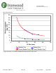
Individual contact force:
BGA Package Depth of penetration (mm) Force per ball (grams)
Typical 1.27mm pitch BGA
i
0.1 20.4
Typical 1.0mm pitch BGA
ii
0.1 16
Typical 0.8mm pitch BGA
iii
0.1 8.1
Notes:
i
0.75mm Nominal solder ball diameter was used in the calculation.
ii
0.6mm Nominal solder ball diameter was used in the calculation.
iii
0.4mm Nominal solder ball diameter was used in the calculation.
Conductive elastomer life: 1700 cycles.
Electrical Specifications 0.5mm Thick 0.75mm Thick
Contact resistance:
23mΩ
1
25mΩ
1
Insulation resistance:
1000MΩ
2
1000MΩ
2
Self Inductance: 0.15nH
3
0.28nH
3
Bandwidth: 10.0GHz 6.5GHz
4
Insertion loss: 1dB@10GHz 1dB@6.5GHz
4
Mutual Capacitance (at PCB): 0.010pF
5
0.011pF
5
Mutual Capacitance (at device): 0.015pF
5
0.015pF
5
Current carrying capacity: 50mA/wire
6
50mA/wire
6
Notes:
1
Maximum contact resistance with 0.2mm compression (contact resistance will decrease with increased compression). Measurements
were taken using 0.4mm square electrodes. The 0.75mm value is interpolated from a test of 0.5mm, 1mm, and 2.0mm elastomers.
2
The test used 0.5mm wide Au plated electrodes with a 0.5mm gap between them. 500VDC was used with a 1mm thick elastomer
compressed 0.35mm.
3
Measurements were taken with a flat gold plated electrode. The 0.75mm value is interpolated from a test of several elastomer
thicknesses ranging from 0.1mm to 2.0mm.
4
This is a conservative estimate based on 1mm thick elastomer test results with test probes spaced at 0.5mm.
5
Measurements were taken with test probes at 0.5mm pitch. The 0.75mm value is interpolated from a test of several elastomer
thicknesses ranging from 0.1mm to 2.0mm.
6
The wires are on a 0.1x0.1mm grid. Multiple wires make contact per solder ball based on its size and depth of penetration.
Operating Temperature
Continuous usage: -35C to +85C
Compression set: 150C for 22hrs
Thickness change: -4.5%
Vibration
Standard: MIL-STD202, METHOD 204, CONDITION A
No change in resistance and thickness
Humidity
Standard: MIL-STD202, METHOD 106
Resistance change: 26 mΩ
Thickness change: -1%
Thermal shock
Standard: MIL-STD202, METHOD 107, CONDITION A
Resistance change: -19 mΩ
Thickness change: -1%
Temperature cycling
Standard: MIL-STD202, METHOD 103, CONDITION A
Resistance change: 15 mΩ