Tel: (800) 404-0204 www.ironwoodelectronics.com GHz BGA Socket User Manual Pa ge | 1 SGB.doc, Rev.
Tel: (800) 404-0204 www.ironwoodelectronics.com GHZ BGA SOCKET USER MANUAL Table of Contents Selecting a BGA socket Socket Mechanics PCB Requirements Backing Plate BGA Socket Assembly MLF (QFN) Socket Assembly: Torque Driver Vacuum Pen Elastomer Cleaning Procedure Surface Mount (SM) Adaptor Thru Hole (TH) Adaptor GHZ socket Mechanical Specifications Elastomer Specification Heat Sink Specifications Pa ge | 2 3 3 4 5 5 6 7 7 8 10 13 14 14 15 SGB.doc, Rev.
Tel: (800) 404-0204 www.ironwoodelectronics.com Selecting a BGA socket The IC package drawing is required to select the correct GHz socket. Go to www.ironwoodelectronics.com. Select the “Products” link, then under the “Browse” menu, select the “GHz BGA & MLF socket” link. For 1.27mm, 1mm, 0.8mm and 0.75mm pitch BGA devices, select the “SG-BGA-6xxx” link. For 0.65mm, and 0.5mm pitch BGA device, select the “SG-BGA-7xxx” link.
Tel: (800) 404-0204 www.ironwoodelectronics.com density application consists of an ultra fine pitch matrix (0.05mm x 0.05mm) of gold plated wires (20 micron diameter), which are also embedded at a 63-degree angle in a soft insulating sheet of silicone rubber. The insulation resistance between connections with 500V DC is 1000 M. The elastomer is ideal for high-current (50mA per filament) applications where a thin, high-density anisotropic connector is required.
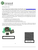
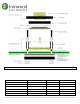
Tel: (800) 404-0204 www.ironwoodelectronics.com Backing Plate For an IC body size of 19mm and above, the GHz socket requires a backing plate to prevent the deflection of the target circuit board due to the high downward forces. If the backside of target PCB contains capacitors and resistors, a custom insulation plate with cavities milled for those capacitors and resistors can be designed. The insulation plate sandwiches between the backing plate and the target PCB.
Tel: (800) 404-0204 www.ironwoodelectronics.com 4. Install the socket top assembly on to the socket base assembly and swivel to lock into the position. If your socket contains a shoulder screw (silver in color), DO NOT tighten them – they are preset at our factory. If your socket uses a black oxide socket head cap screw, tighten them until they make contact with the lid. 5. Turn the compression screw clockwise, until it makes contact with the compression plate and/or the BGA package. 6.
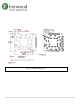
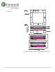
Tel: (800) 404-0204 www.ironwoodelectronics.com Figure 5: Exploded View Socket Assembly Torque Driver Select the appropriate Ironwood torque driver for your socket torque specified on page 1 of the part drawing. The following adjustable drivers are sold separately and include hex bits listed in table. For other bits, please call Ironwood Tech Support @1-800-404-0204. Part Number Range Increments TL-Torquedriver-01 20-100 in. oz. 16 in. oz. Included Hex Bits 1.
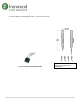
Tel: (800) 404-0204 www.ironwoodelectronics.com Legend HBA-¼” hex bit adaptor (accommodates other ¼” hex drive insert bits). Torque Conversion Factors 1 in. lbs. = 16 in. Oz. = 0.113 Nm Vacuum Pen A vacuum pen is recommended for insertion/extraction of ICs. Figure 7 shows a typical vacuum pen. TL-vacuumpen-01 can be purchased separately. Hand insertion of ICs and extraction using a small tweezers are also acceptable.
Tel: (800) 404-0204 www.ironwoodelectronics.com Required Tools: Scotch™ Magic™ Transparent tape or similar or poster putty – Henkel™ DUCPTY2 Poster Putty, Removable/Reusable, Nontoxic or a similar brand. (For more thorough cleaning technique use alcohol, De-Ionized (DI) water, a stiff nylon brush, and clean, dry shop air.) The Elastomer can be quickly cleaned of dust and debris with a piece of transparent tape approximately 2 inches long. Remove the complete socket assembly from the board.
Tel: (800) 404-0204 www.ironwoodelectronics.com For a more thorough cleaning, use the stiff nylon brush and a solution of half DI water and half isopropyl alcohol. Wet the brush, scrub the surfaces of the elastomer, and blow both sides dry with clean, dry shop air. After allowing to fully dry, clean the surfaces with the rolled tape method to remove any dust or lint accidentally deposited in the drying process. Only perform the thorough cleaning with the elastomer removed from the elastomer guide.
Tel: (800) 404-0204 www.ironwoodelectronics.com recommends contacting your solder paste / flux manufacturer for proper reflow profiles for your particular setup and equipment. Recommended Reflow Profile – Low Temperature (Non-RoHS) Ironwood's SMT adaptor closely emulates a BGA package and therefore can employ similar processes to attach it to a target board.
Tel: (800) 404-0204 www.ironwoodelectronics.com Recommended Reflow Profile – High Temperature (RoHS) Figure 12: Recommended Reflow Profile – High Temperature (RoHS) (4) Surface tension between the adapter's solder spheres and the target PCB's pads will self-align the part during the reflow process.
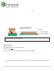
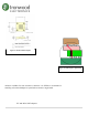
Tel: (800) 404-0204 www.ironwoodelectronics.com Thru Hole (TH) Adaptor If the target circuit board exists with a thru-hole pattern, then a TH adaptor can be used with a GHz socket. TH adapter (See figure 13) has terminal pins on the bottom side and round pads on the topside. It is slightly larger than the IC size. It has threaded insert on four corners. GHz socket can be mounted on to this adapter using the screws that mate into the threaded insert.
Tel: (800) 404-0204 www.ironwoodelectronics.com GHZ socket Mechanical Specifications Individual contact force BGA Package Depth of penetration (mm) Force per ball (grams) Typical 1.27mm pitch BGAi 0.1 20.4 Typical 1.0mm pitch BGAii 0.1 16 Typical 0.8mm pitch BGAiii 0.1 8.1 Notes: i 0.75mm Nominal solder ball diameter was used in the calculation. ii 0.6mm Nominal solder ball diameter was used in the calculation. iii 0.4mm Nominal solder ball diameter was used in the calculation.
Tel: (800) 404-0204 www.ironwoodelectronics.