Rain Dial UGuide New 4/3/07 8:10 AM Page i 6-, 9- and 12-Station Irrigation System Controller New Rain Delay Feature • Postpones automatic watering up to 9 days! (See page 24 for details.
O Table of Contents Key Features . . . . . . . . . . . . . . . . . . . . . . . . . . . . . . . . . . . . . . 2–3 Getting Started . . . . . . . . . . . . . . . . . . . . . . . . . . . . . . . . . . . . . . . 4 Battery Installation and Armchair Programming . . . . . . . . . . 4-5 Overview: Control Module Interface . . . . . . . . . . . . . . . . . . . . 6-7 Overview: Internal Controller Components . . . . . . . . . . . . . . 8-9 Installation Procedures . . . . . . . . . . . . . . . . . . . . . . . . . . . .
Special Functions and Features . . . . . . . . . . . . . . . . . . . . . 24–29 Rain Delay Feature . . . . . . . . . . . . . . . . . . . . . . . . . . . . . . . . . 24 Water Budget Feature . . . . . . . . . . . . . . . . . . . . . . . . . . . . . . . 24 Stack/Overlap Control Feature . . . . . . . . . . . . . . . . . . . . . . . . 25 MV/Pump per Station Feature. . . . . . . . . . . . . . . . . . . . . . . . . 26 Well Recovery Delay Feature . . . . . . . . . . . . . . . . . . . . . . . . .
O Key Features Congratulations! You have selected one of the most feature-packed yet simple-to-use sprinkler system controllers available. To acquaint yourself with your new controller, take just a few minutes to review some key Rain Dial features, then follow the recommended procedures for installation, programming and operation. • Modular design – Provides easy access to valve wiring terminals and battery. Simple, snap-out control module for convenient “Armchair” programming before installation.
• Live programming – Enables programming changes to be made at any time—even during watering! • Fully automatic, semi-automatic and manual station operations. • Manual Advance – Enables quick manual advance up through the station sequence. Works in all Automatic, Semi-auto and Manual operations. • Off or Stop – Immediately stops and prevents all watering activity without disturbing Programs.
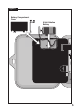
O Getting Started Battery Installation & Armchair Programming Installing the 9V battery serves two important purposes: first, to enable the Rain Dial to be fully programmed prior to installation, and second, to keep the control module synchronized with current time and date during a main power interruption lasting more than 24 hours. The control module is designed to be easily removed for complete programming in a more convenient setting, such as your favorite armchair.
Figure 1 Battery Compartment Cover 9-Volt Alkaline Battery EA GRO 5
Overview: Control Module Interface 1 - Program Switch • Three-position slide switch used to select Program A, B or C for setup, program review and manual operation. 2 - LCD Display • High-contrast LCD panel displays all controller programming and operating information. 3 - Plus and Minus Buttons • Push buttons used to increase and decrease display values during controller setup, programming and manual operations. Adjusts values incrementally (press and release) or by rapid scrolling (press and hold).
Rain Dial UGuide New 4/3/07 8:12 AM Page 7 Figure 2 2 1 3 4 7 5 6 7
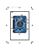
Overview: Internal Controller Components 1 - Battery Compartment • Snap-in cover provides easy access to 9V alkaline battery. 2 - Control Module Ribbon Cable • Quick disconnect for easy removal of control module from cabinet to facilitate Armchair Programming or service. 3 - Ground Terminal (EARTH GROUND) • Connection terminal for earth ground conductor wire. 4 - 2A Slow-blow Fuse • Safety fuse provides current overload protection to the 24 VAC power source caused by a short-circuit condition.
Figure 3 1 2 4 3 5 EARTH GROUND 7 8 9 10 11 12 VC 24 VAC 6 1 2 3 4 5 6 MV/ PUMP 7 9 8 9
O Installation Procedures Installing the Controller Cabinet Locate the indoor model in a protected area, such as a garage, within 5' (1.5m) of a grounded electrical outlet. Locate the outdoor model avoiding direct exposure to sun and irrigation spray. Do not install the controller within 5' (1.5 m) of any motorized equipment. 1. Drive a #10 wood screw (provided) into a wall stud, at a convenient level, leaving about 1/4" (6.5 mm) of the screw exposed.
6. Connect the Valve Common wire to the terminal labeled “VC.” 7. Connect the master valve or pump start relay control wire (if applicable) to the terminal labeled “MV/PUMP.” Note: The controller does not supply power to operate the pump. The pump start relay or master valve must have a nominal coil voltage of 24 VAC at 0.375A. Figure 4 Valve Common Wire to Terminal “VC” Sprinkler Control Valves (0.5A max.
Connecting the Earth Ground Note: The built-in circuit protection in all Rain Dial controllers requires an earth ground path, such as a copper-clad ground rod or metal water pipe, to help protect the controller from power surges, and is especially important in lightning-prone areas. 1. Connect a 12–16 gauge solid-copper wire to the ground device and route into the controller cabinet through the field wire opening. 2. Secure the ground wire to the terminal labeled “Earth Ground.
Connecting the Power Source Indoor Models 1. Route the plug-in transformer cable through the small hole provided in the bottom of the cabinet. 2. Tie a knot in the cable to provide a strain relief, and connect the wires to the terminals labeled “24 VAC” (in either order). 3. Close the control module and plug the transformer into a wall outlet. The controller is now ready to program and operate.
Connecting the Power Source Outdoor Model WARNING: All electrical components must meet applicable national and local electrical codes including installation by qualified personnel. These codes may require a junction box installed on controller’s 1/2" NPT nipple and a means in the fixed wiring of disconnecting AC power having a contact separation of at least 0.120" (3mm) in the line and neutral poles. The connection wire must have insulation rated @ 105° C min.
Figure 7 1/2" (13 mm) Conduit Body Neutral to White Equipment Ground to Green Figure 8 Hot to Black Key Station Test Run Feature The Station Test Run feature enables all stations to be automatically operated in sequence using a temporary run time from 1 to 10 minutes. Perfect for a quick check of the system after installation or service. 1. Place the Function switch in the Run position. 2. Turn the Dial to the Skip Days / Special Functions position. 4.
O Getting the Most from Your Rain Dial Controller • The basic watering cycle – Once a program is given a start time, it causes each station with an assigned run time in the program to operate in sequence, beginning with the lowest numbered station. When all stations have run in sequence, the watering cycle is over. • Avoid unexpected start times – It is possible to set a second start time that begins before the cycle from the first start time has finished.
Why three watering programs? – Different plant types requires varying amounts of water. Rain Dial allows you to segregate different plant types and assign watering in three different programs (A, B & C). The following example below shows how this can be accomplished: Sample Watering Plan Program Start Time A (#1) 5:00 AM B C (#1) 3:00 PM (#1) 4:00 AM (#2) 7:30 PM Valve # Location 1 2 3 4 5 5 Front Lawn Back yard Side Yard Trees drip Garden Garden Run Time Schedule 15 min. 15 min. 10 min. 2 hrs.
What the Display Indicates Information Displayed When Programming The Display will show the following information with the Function switch in the Set Programs position, in conjunction with the following Dial settings: Valve Run Time - Shows run time in minutes or hours. Also displays OFF for unused valves. Start Times - Displays Program time or OFF for unused start times. Skip Days - Shows days numbered 1–31, or OFF and Once Every will be displayed. Schedule - Displays ON or OFF.
Pump circuit On/Off during well recovery Indicates if pump circuit will be On or Off during a well recovery period. Program Stacking/Overlap - If program stacking is selected, 1:on will be displayed. If program overlap is selected, 3:on will be displayed. Information Displayed During Operation With the Function Switch in the RUN position and the dial set to Current Time, the currently operating valve number will be displayed.
O Basic Programming Procedures Setting the Current Time and Day 1. Place the Mode Switch in the Set Programs (center) position. 2. Turn the Dial to the Current Time position. 3. Use the and buttons to set the current time (note the correct AM/PM designation). Hold the button down to scroll. 4. Turn the Dial to the Today position. 5. Use the and buttons to set the current day (abbreviation). 6. Turn the Dial to the Current Time position when finished.
1. Place the Function switch in the Set Programs position. 2. Place the Program switch to select A, B or C. 3. Turn the Dial to the Start Time 1 position. 4. Use the and buttons to set the start time. Hold the button down to scroll. The display will continuously scroll through the minutes and hours. Note: To turn a Start Time OFF, select one increment past 11:59 or 5:59 (AM or PM). 5. Repeat steps 3 and 4 for the remaining program cycle start times you wish to set. 6.
To Set a Skip Days Schedule: Note: To set a Skip Days schedule, Odd/Even mode must be OFF. 1. Place the Function switch in the Set Programs position. 2. Place the Program switch to select A, B or C. 3. Turn the Dial to the Skip Days /Special Functions position. 4. Use the and buttons to select Once Every 01–31 to set the Skip Day interval. Note: Once a Skip Days interval is selected, OFF will be replaced with “Once Every” and the Skip Days number you select. 5. Turn the Dial to the Today position. 6.
8. Press the Manual button one time to select the Day setting. 9. Use the and buttons to select the current calendar day. For example, April 4 would be displayed as A:04. 10. Press the Manual 11. Use the and button one time to select the Year setting. buttons to select the year (2007 = 07). 12. Turn the Dial to the Current Time position when finished. 13. Place the Function switch in the Run position.
O Special Functions and Features Rain Delay Feature The Rain Delay enables the Rain Dial to suspend all automatic watering activity from 1 to 9 days. 1. Place the Function switch in the OFF position. 2. Press the button to set 1 to 9 delay days (OF 1 – OF 9). 3. Place the Function switch in the Run position. The display will begin alternating between the current time and the number of delay days remaining.
Stack/Overlap Control Feature The Stack/Overlap Control feature provides the option to restrict operation to one Program or station at a time (stacked) or to enable three Programs or three stations to operate concurrently (overlap). Note: The Stack option prevents another Program or station from starting until the one in operation is finished. If a Program’s start time is delayed past midnight it will not run.
MV/Pump Control per Station Feature This feature enables the MV/Pump circuit to be automatically turned On and Off by specific station as needed, where only certain stations require a booster pump to increase system pressure. The default setting is pump On (P:ON) for all stations. Note: Applies to the station regardless of it’s Program assignment. 1. Place the Function switch in the Set Programs position. 2. Turn the Dial to the desired station number (station run time will be displayed). 3.
Pump Control During Well Recovery The Pump Circuit Control feature enables the pump or master valve to be automatically turned On or Off in conjunction with the Well Recovery Delay feature. The pump/master valve circuit is energized at the beginning of the watering operation and remains on for the duration of the cycle. In some systems, the pump is not pressure limited and will continue to operate during a delay in the watering cycle, causing a pump “Dead Head” or over-pressure condition.
Diagnostic Circuit Breaker Feature The message “FUS” and the malfunctioning station number will be displayed if a short circuit is detected. The station will be bypassed during the watering cycle enabling the remaining stations in the watering cycles to run. The FUS display will alternate with the current time display. IMPORTANT: Determine the cause of the problem and take corrective action as necessary. With the Dial set in the Current Time position, press any button to clear the “FUS” display.
Factory Default Reset Feature The Rain Dial factory default Program settings are as follows: Current Time: 12:00 AM. Current Day: Sunday. Current Date: January 1, 2006. Program A: Weekday watering schedule with all days active. One start time at 7:00 AM. All stations have 10-minute run time. Program B and C: No watering days, station run times or start times. Skip Days and Odd/Even day schedule: OFF - all Programs. Excluded days in Skip Days or Odd/Even schedule: None. MV/Pump operation: ON - all stations.
O Manual Operations Semi-Automatic Operation Semi-Automatic operation enables a selected Program watering cycle to be started manually. Once running, the manual advance feature enables you to step through the programmed station sequence. 1. Place the Function switch in the Run position. 2. Turn the Dial to the Current Time position. 3. Place the Program switch to select A, B or C. 4. Press the Semi-Auto button to start the watering cycle.
Manual Station Operation Manual Station operation provides manual control at the individual station level and provides the following four control options: • Station(s) can be operated for a one-time run duration without altering the station’s set run time in an automatic Program. • Operation can be limited to only one station running manually or set to allow three stations to run at the same time. Note: Refer to “Program Stack/Overlap Control” on page 25 for additional information on this feature.
O In Case of a Problem... If a problem arises with your new Rain Dial controller that cannot be resolved with the following troubleshooting solutions, give us a call and we will be glad to help. Our Customer Support Team is available to answer any question or concern you may have regarding your Rain Dial controller or any Irritrol product. Call us toll-free at 1-800-634-TURF (8873), Monday through Friday, 7:30 AM to 4:00 PM (Pacific). Also, see us online at: www.irritrol.
Problem Possible Cause Correction Watering at wrong times. Current Time of day incorrectly set. Reset to current time (correct AM or PM). Blank display No power. Check circuit breaker panel, wiring connections, transformer and 2A fuse. Program won’t display. Wrong Function switch setting. Place Function switch in the Run position. Controller is currently in a watering cycle. Check or change program with Function switch in Set Programs.
O Replacing the Fuse The Rain Dial utilizes a 2.0A Slow-blow fuse to protect the controller on the 24 VAC input power. If the fuse blows, check for the probable cause of the condition and take corrective action before replacing the fuse. WARNING: The 2.0A safety fuse protects the transformer from damage due to a current overload (short circuit) condition. For continued protection against risk of fire, replace only with the same fuse type and rating.
O Remote Control Feature The Rain Dial controller is remote-ready and is fully compatible with both Irritrol Handheld Remote Control models: the close-range residential model KSR-KIT, and the long-range commercial model CMR-KIT. Both remote models offer the same convenient remote control features. Refer to the user guide provided with each remote kit for complete information.
similar, but are not interchangeable. O Specifications Outdoor Models: • Input: 120 VAC 60 Hz, 30 VA (Domestic), 230 VAC, 50 Hz, 30VA (International) 240 VAC, 50 Hz, 30VA (Australia) Indoor Models: • Input: 24 VAC, 60 Hz, 30 VA (domestic) or 24 VAC, 50 Hz, 30 VA (International and Australian) All Models: • Station Output: 24 VAC at 0.5A, 1.0A (maximum total) • Master Valve/Pump Start Relay Output: 24 VAC at 0.375A • 2.
O FCC Rules Domestic: This equipment has been tested and found to comply with the limits for a Class B digital device, pursuant to Subpart J of Part 15 of the FCC Rules. These limits are designed to provide reasonable protection against harmful interference in a residential installation. This equipment generates, uses and can radiate radio frequency energy and, if not installed and used in accordance with the instructions, may cause harmful interference to radio communications.
For Product Inquiries: U.S.A. P.O. Box 489 Riverside, California 92502 Tel:(909) 785-3623 (800) 634-8873 Australia Irritrol PTY Ltd. 53 Howards Road Beverley, SA 5009 Tel: (08) 8300 3633 Europa Irritrol Europe s.p.a. Via dell’Artigianato, 1/3-Loc Prato della Corta 00065 Fiano Romano (Roma), Italia Tel: (39) 0765 455201 © 2007 Irritrol • www.irritrol.com Form Number 373-0428 Rev.