
Owners Manual
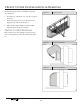
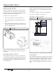
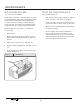
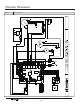
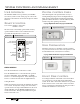
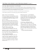
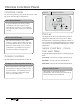
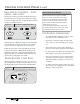
Table Of Contents
- Introduction
- Applications
- Product Overview
- Chassis Features and Benefits
- Ordering Data - EZ Series 42
- Performance Data - EZ Series 42
- Ordering Data - EZ Series DR (DR.PTAC)
- Performance Data - EZ Series DR (DR.PTAC)
- Dr. PTAC Features
- Dr.PTAC information
- Dimensional drawings
- Options and Accessories
- Clearances and Projections
- Installation Instructions
- Wall Sleeve Installation Instructions
- Condensate Drain Kit
- Rear Grille Installation Instructions
- Subbase Assembly & Installation
- Chassis Installation
- Front Cover Installation & Removal
- Fresh Air Vent
- Maintenance
- Information for Heat Pump units
- Electrical Installation
- Wiring Diagram
- System Controls and Management
- Digital Control Panel
- Remote Thermostats
- Remote Thermostat Interface
- Control Board
- Temperature Limiting
- Error Codes
- Performance Specifications
- Warranty

Manufacturer of Quality Air Conditioning and Heating Products • www.islandaire.com • sales@islandaire.com • (800)-886-2759
38
Digital Control Panel (cont.)
Fan Speed Control - Low,
High, and Auto
e fan speed settings are adjusted with the Fan button.
Each time the button is depressed it changes the setting
between Low, High and Auto. A light will indicate which
setting is currently being used.
AUTO
Figure 42 Fan Controls - Digital Control Panel
If either the Low or High fan settings are selected the fan
will continuously operate in the selected Low or High
speed even if the set temperature has been reached.
When the Auto feature is selected, while the air condi-
tioner is in the COOL or HEAT mode, the fan speeds
will change between low and high automatically as the
temperature in the room changes and the fan will cycle
o when the set temperature is reached.
Temperature Controls
e Warm and Cool buttons are used to raise or lower
the set temperature. By depressing both buttons at once,
the display will toggle between Celsius and Fahrenheit.
Figure 43 Temp Controls - Digital Control Panel
AUTO
If the temperature in a vacant room falls
below 50 °F (4.4 °C) the freeze prevention
thermostat automatically starts the heating
cycle to prevent freezing conditions. All
other operations will be disabled until the
temperature rises above
58 °F. When the temperature of the freeze
prevention thermostat rises above 58 °F, the
system will resume normal operation.
Freeze Protection Feature
Operating Guidelines
• Do not block airow. Ecient operation of the
unit depends on free circulation of air.
• Paper, leaves, and other debris can reduce e-
ciency and cause serious damage to the compres-
sor.
• Ensure that objects such as drapes, furniture, or
plants are not blocking supply and return airow.
• Do NOT operate unit with front panel removed or
without lter, as this will void any warranties.
• Keep doors and windows closed. Leaving them
open will increase the workload on the unit and
will result in higher operating cost and excessive
condensate.
• Do NOT operate unit during construction. Con-
struction dust can clog lter and cause permanent
damage to other components.