EZ Series 42 & EZ Series DR (DR.PTAC) 42” W x 16” H PTAC/PTHP Perfect fit for Replacing Existing 42” x 16” Units and for New Construction Projects AHRI Certification applicable to EZ42 models only Engineering Manual MA N U FAC T U R E R O F QUA L IT Y A IR CO N DITION IN G A N D HEATIN G PRODUC TS 6140207 Rev.
Table of Contents Introduction................................................................ 1 Applications................................................................... 2 New Construction........................................................................ 2 Retrofit/Replacement................................................................... 2 Application Considerations........................................................ 3 Guaranteed Quality.................................................
Introduction Our Company Islandaire is the fastest growing specialty air conditioning and heating manufacturer in the country. Founded in 1992 by Robert Hansen, it has grown into a multi-million dollar company in just a few short years. Islandaire builds a full complement of high quality thru-the-wall replacement air conditioners and heat pumps, water source heat pumps, and gas units in St. James, New York.
Applications The EZ Series 42 and DR units are designed and manufactured for new construction or the replacement of packaged terminal air conditioning (PTAC) units in an existing building. Our packaged terminal air conditioning (PTAC) units provide year-round comfort control for hotels, motels, apartments, dormitories, shops, nursing homes, assisted living centers, satellite offices, room additions and other applications that require economical heating and cooling.
Applications (cont.) Application Considerations Guaranteed Quality It is important for air conditioning systems to be properly sized for each application in order to achieve desired temperature and humidity levels. It is strongly recommended that a professional engineer match the PTAC units with the building structure and climate. Each Islandaire unit is designed to operate quietly and efficiently and is backed by the best warranty program available.
Product Overview Quiet Operation Seacoast Construction The cross-flow tangential fan wheel design used in our EZ42 and EZDR units provide whisper quiet operation while delivering maximum airflow required for proper air circulation. Separate indoor and outdoor fan motors further reduce operating sound levels and costs. Application of air conditioning equipment in a corrosive environment requires special consideration.
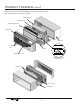
Product Overview (cont.) Islandaire manufactures the EZ42/EZDR loaded with standard features that other manufacturers often consider optional. VENTURI SHROUD SLINGER FAN BLADE TANGENTIAL BLOWER WHEEL DISCHARGE GRILLE WALL SLEEVE RETURN AIR FILTERS CHASSIS AUTO REMOVABLE FRONT PANEL DIGITAL TOUCHPAD CONTROL / DIAGNOSTIC CENTER COMPRESSOR FRESH AIR INTAKE SLOPED BASEPAN Manufacturer of Quality Air Conditioning and Heating Products • www.islandaire.com • sales@islandaire.
Chassis Features and Benefits Slide Out Chassis • Slide-out chassis makes installation simple • All components are readily accessible to service personnel • On-board diagnostic software and display help diagnose potential problems • Designed to replace older units with minimal modification • Isolated rotary compressor design for continuous efficient, reliable and quiet operation See page 28 for chassis installation instructions Wall Sleeve Part Number 2401135-00 • Thick insulation on the top and sides to
Chassis Features and Benefits (cont.
Ordering Data - EZ Series 42 Model Nomenclature Control choices include a unit mounted digital control; multiple wired wall mounted heating/cooling thermostats and a wireless wall thermostat, with occupancy sensor control. Please review the nomenclature/model number breakdown below for the EZ Series 42 options. Units are available in four cooling BTUH sizes: 7,500; 9,500; 12,000; 15,000 Voltage options are: 115V, 208/230V, and 277V.
Performance Data - EZ Series 42 Performance Data for EZ42 Series MODELS EZ07 EZ09 EZ12 EZ15 230 208 277 115 230 208 277 115 230 208 277 230 208 277 BTUH COOL 7,200 6,800 7,200 9,800 9,500 9,300 9,500 12,500 12,500 12,300 12,500 14,500 14,300 15,000 AMPS COOL 2.46 2.52 2.11 7.22 3.41 3.70 2.83 9.30 4.65 5.05 3.86 5.96 6.49 5.20 WATTS COOL 565 525 585 830 785 770 785 1,070 1,070 1,050 1,070 1,370 1,350 1,440 EER 12.8 13.0 12.3 11.8 12.1 12.
Ordering Data - EZ Series DR (DR.PTAC) Model Nomenclature Control choices include a unit mounted digital control; multiple wired wall mounted heating/cooling thermostats and a wireless wall thermostat, with occupancy sensor control. Please review the nomenclature/model number breakdown below for the EZ Series DR options. Units are available in four cooling BTUH sizes: 7,500; 9,500; 12,000; 15,000 Voltage options are: 208/230V and 277V.
Performance Data - EZ Series DR (DR.PTAC) Performance Data for EZDR Series MODELS EZ07 EZ09 EZ12 EZ15 230 208 277 230 208 277 230 208 277 230 208 277 BTUH COOL 7,200 6,800 7,000 9,500 9,300 9,200 12,000 11,800 12,000 14,500 14,300 15,000 AMPS COOL 2.63 2.74 2.09 3.63 3.82 2.89 4.98 5.31 4.08 6.17 6.73 5.36 WATTS COOL 605 570 580 835 795 800 1,145 1,105 1,130 1,420 1,400 1,485 EER 11.9 11.9 12.1 11.4 11.7 11.5 10.5 10.7 10.6 10.2 10.2 10.
Dr. PTAC Features ACCESSORIES: FEATURES: • Condensate removal kit • Up to 55 CFM Continuous Conditioned fresh air • 18 gauge insulated wall sleeve • Motion sensor/door switch capable • Wired remote thermostat • Superior temperature control • Wireless remote thermostat • Dehumidification of room air • I.R.
Dr.PTAC information The Dr. PTAC system is an add on system to our standard PTAC unit to provide conditioned makeup air into a space thru the PTAC unit by providing up to 55 CFM of outdoor air 24/7 by forced fan and cycling dehumidifier compressor based on outdoor relative humidity levels. Dr. PTAC was created to solve issues with dehumidification in rooms and to introduce fresh air due to deficiencies of oxygen levels. Dr. PTAC is not only a PTAC but a Conditioned Make Up Air unit.
Dimensional drawings Units must be installed in accordance with all applicable codes. Ensure that there is adequate clearance for servicing and proper operation. A minimum of 18 inches in front of the chassis is required. Provide additional space for service technician to work on the unit. Ensure that drapes, beds, bedspreads, furniture, etc., DO NOT block either return or discharge air openings.
Options and Accessories Hard Wire Kit Part Number 6040756 • Used in place of a plug-in power cord • All 265V units require either a hard wire kit or electric subbase See page 31 for electrical information Remote Control Part Number 6040694 • Ability to control PTAC from anywhere in the room • Large full function display • Operates on two AA batteries Optional 2 Stage Heater Available on 208/230 Volt Units With Remote Thermostats • Reduces energy cost during the heating season • Maximizes year-round comfo
Clearances and Projections Minimum Projection Into room Figure 2 The wall sleeve will need to be installed so that the sleeve projects into the room a minimum amount according to the table below. OPTION Minimum Projection Into Room OUTSIDE WALL MINIMUM PROJECTION ROOM SIDE MINIMUM ROOM SIDE PROJECTION (SEE TABLE) 1/4” MINIMUM INCHES (MM) WALL SLEEVE ONLY .25 (6) 4.5(114) SUBBASE KIT LEVELING LEGS KIT WALL SLEEVE 2 (50) DUCT KIT 1.0 (25.
Installation Instructions Installation of the PTAC unit involves four main components and various accessory components. The main components are the wall sleeve, chassis, rear grille, and decorative front. The accessory components are subbase, condensate drain, duct kits, and hardwire cable. Figure 5 Main Installation Components FRONT PANEL CHASSIS WALL SLEEVE CAUTION! To prevent damage, this unit should NOT be operated to provide supplementary heating and cooling during the construction period.
Wall Sleeve Installation Instructions Preparing the Wall Opening • Once a satisfactory location is found and height of unit is determined, create a wall opening to install the wall sleeve. The rough opening should measure a minimum of 16 ½” high x 42 ½” wide. • If opening will start right at the finished floor level, leave enough clearance for carpeting, etc. If using a power cord, leave enough space for the cord to exit from under the front panel.
Wall Sleeve Installation Instructions (cont.) Wall Sleeve Installation Figure 8 After the wall opening is checked for location, size, and clearances, proceed to wall sleeve installation. Wall Sleeve Installation WALL OPENING 1. Install Condensate Drain Kit (if applicable). 2. Slide the wall sleeve into the wall opening. The unit chassis must fit snugly and uniformly into the wall sleeve without distortion. 3. Make sure the sleeve is within the range of minimum projections as outlined on the next page.
Condensate Drain Kit Condensate Drain Kit NOTE Part Number 4090661 This drain kit serves only as a link between the unit and field-supplied condensate drain system. An indoor/outdoor drain kit is available as an accessory item. When a drain kit is to be installed, do so before installing the wall sleeve in the wall. Installing the kit without connecting it to a drainage system will result in inadequate condensate removal, possible leakage and corrosion.
Condensate Drain Kit (cont.) Internal Drain Installation Figure 13 Internal Drain Location DETERMINE LOCATION OF INTERNAL DRAIN. DRILL MOUNTING HOLES ACCORDING TO TEMPLATE Part Number 6140165 The drain kit can be installed as an internal drain on the bottom of the wall sleeve to allow condensate to drain into an internal drain system inside of the building. Locate the drain so that it will be on the room side of the wall when the cabinet wall sleeve is installed.
Rear Grille Installation Instructions Stamped Rear Grille Standard Grille Fastener Figure 16 Part Number 6070264 The rear grille directs condenser airflow and provides a protective barrier for the outdoor coil. Either the approved Standard or Architectural grille must be installed before installing the chassis. STANDARD GRILLE Standard louvered grille installation 1. Prepare the grille for installation by installing the five plastic fasteners supplied through the holes in the grille. 2.
Rear Grille Installation Instructions (cont.) Architectural Rear Grille Figure 20 Threaded Stud Installation Part Number 6070422 The rear grille directs condenser airflow and provides a protective barrier for the outdoor coil. Either the approved Standard or Architectural grille must be installed before installing the chassis. STUD ARCHITECTURAL GRILLE Architectural louvered grille kit installation WASHER INSTALL THE FOUR THREADED STUDS INTO THE THREADED OPENINGS ON THE INSIDE FACE OF THE GRILLE.
Rear Grille Installation Instructions (cont.) Figure 22 Wall Sleeve Dimensions and Mounting Hole Locations for Installation of Exterior Louver Grille by Others TYPICAL HOLE & MOUNTING STUD LOCATION UPPER MOUNTING HOLES LOCATION & DIMENSIONS .218 .688 .250 .450 .375 .500 .079 .444 1.525 .227 .725 1.525 .250 .725 .250 WINDOW FRAME (LOUVERS NOT SHOWN) WALL SLEEVE .725 39.750 I.D. .9.000 STUD LOCATION (CENTER TO CENTER) 13.887 I.D. 3.150 .700 6.175 14.075 14.075 1.919 1.500 1.919 .700 .
Rear Grille Installation Instructions (cont.) Figure 23 Wall Sleeve Dimensions and Mounting Stud Locations for Installation of Exterior Louver Grille by Others 42.00 PTAC WIDTH 39.75 PTAC I.D. .125 SHEET METAL THICKNESS .725 27.00 .725 4.75 STUDS C/C 40.55 .125 SHEET METAL THICKNESS LOUVER HEIGHT WINDOW HEIGHT 9.000 STUDS C/C 16.06 PTAC HEIGHT 3.150 LOUVER WIDTH WINDOW WIDTH Manufacturer of Quality Air Conditioning and Heating Products • www.islandaire.com • sales@islandaire.
Subbase Assembly & Installation Subbase Assembly & Installation Figure 24 Assembled Subbase Figure 25 Subbase Installation Electrical Subbase Assembly An electrical Subbase provides a convenient location for unit wiring to be connected to building wiring. It also provides support for the indoor portion of the unit. Subbase Selection Select a subbase according to the power requirements of the unit. See Subbase Selection chart on page 27.
Subbase Assembly & Installation (cont.) Figure 26 Subbase Nomenclature SUBBASE SELECTION CHART EZSB 42 05 BP R12 S00 F15 V01 TYPE EZSB - Sub Base MODEL TYPE 16 - Amer. Air Filter 16 25 - Amer. Air Filter 25 40 - Amer. Standard SR40 41 - Amer. Standard TW41 42 - Islandaire 42 x 16 45 - Amer. Standard 45 5R - Ice Cap 5R 61 - Climate Mstr. 801 8S - Climate Mstr.
Chassis Installation 1. Remove the cabinet front from the chassis as described in Front Removal. Figure 27 CHASSIS 2. Insert the chassis into the wall sleeve. Chassis Installation WALL SLEEVE 3. Slide the chassis into the wall sleeve until the chassis flanges contact the front edge of the wall sleeve. 4. Secure the chassis to the wall sleeve using two screws on each side of the chassis to ensure a proper seal between the chassis and the wall sleeve.
Front Cover Installation & Removal Use the following procedure to install the front panel onto the chassis: Figure 29 Front Cover Tabs 1. Attach the top of the front cover onto the top edge of the chassis. 2. Swing down the front cover over the chassis and apply pressure until it locks into place. 3. Make sure that digital display opening and filters align with proper locations on chassis.
Fresh Air Vent Fresh Air Vent The kit consists of a main duct for the room of origin and an extension duct to reach the adjoining room and terminal duct. The vent control allows outside air to be drawn into the conditioned area. This outside air can provide ventilation when the blower is operating, but it will increase the heating or cooling load and operating costs.
Maintenance Air Intake Filters Routine Maintenance (2 per) Part Number 6080067 Keep air intake filter clean. When the air conditioner is operating, indoor air is filtered and refiltered continuously trapping airborne dirt and dust in the washable filter. The air intake filters are removable for easy cleaning. A clean filter helps remove dust, lint, and other particles from the air and is important for best cooling and operating efficiency.
Information for Heat Pump units Heat pump models offer substantial savings over models with conventional electric resistance heaters. Reversing Valve: The reversing valve controls the direction of refrigerant flow for both heating and cooling functions and remains energized as long as the controls are in the heat position. When the cooling controls are activated, the valve automatically reverses to the cooling position.
Electrical Installation Hardwire Kit Figure 35 Hardwire Kit Figure 36 LCDI Cord Part Number 6040756 Cord connection to a wall socket is not permitted for 265 volt units. All 265 volt units must be hard-wired using the hard wire kit or make use of the plug-in receptacle in the standard subbase. LCDI Cords 230/208V units are equipped with LCDI or AFCI power cords and can open the electrical circuit to the unit.
Wiring Diagram BLACK BLUE WHITE YELLOW NOT USED EZ42 WT LIMIT & FUSIBLE LINK Wiring Diagram HYDRONIC HEAT PUMP ELECTRIC HEAT GAS HEAT FREEZE PROT RESTART WSHP Y REMOTE WSHP RD Figure 37 Manufacturer of Quality Air Conditioning and Heating Products • www.islandaire.com • sales@islandaire.
System Controls and Management User Interfaces Digital Control Panel The Islandaire PTAC can be operated by several different control systems. Listed on this page are some of the important control features and a brief description of their functions. The built-in digital control panel features an easy to read digital display, large buttons and bright indicator lights.
System Controls and Management (cont.) System Management Software The Islandaire PTAC unit is equipped with an on-board control system that contains system management software and sensors. Built in safety features protect the unit from the damaging effects of freezing temperatures and power interruptions. Energy management features allow unit performance to be customized and control power consumption. System monitoring software helps service personnel quickly correct any problems.
Digital Control Panel Control panel Figure 41 Digital Control Panel Use the control panel to power on/off, select mode, select fan speed, and adjust the set temperature. Auto Restart Feature To prevent multiple units from powering up simultaneously after a power outage, there will be a random 5 to 15 second delay before the unit turns on after power has been restored. AUTO Display The display shows the room temperature (return air temperature) when the unit is in operation.
Digital Control Panel (cont.) Fan Speed Control - Low, High, and Auto Freeze Protection Feature If the temperature in a vacant room falls below 50 °F (4.4 °C) the freeze prevention thermostat automatically starts the heating cycle to prevent freezing conditions. All other operations will be disabled until the temperature rises above 58 °F. When the temperature of the freeze prevention thermostat rises above 58 °F, the system will resume normal operation.
Remote Thermostats Remote Thermostat Control Remote Control Node Used with a wireless wall thermostat, the RCN communicates with the thermostat using unlicensed 900 MHz, radio frequency energy. The PTAC unit can be controlled by any remote electronic thermostat that can interface with RCBWYG terminals. A wiring harness is provided with conductors for all applications (Heat Cool, Heat Pump, Multispeed Fan, etc.). See details on the next page. The Control Selection jumper must be in T’STAT position.
Remote Thermostat Interface The remote thermostat interface terminal block is located on the power module board. A Wiring harness is provided with conductors for all applications (Heat Cool, Heat Pump, Multispeed Fan, etc.). It provides a connection for remote thermostat and energy management inputs. To convert to thermostat operation: 1. Shut main power to unit off. 2. Access main control board and turn remote thermostat dip switch on. 3. Plug in the supplied thermostat harness. 4.
Control Board Figure 13 Control Board Physical Features U T S R Q P O N M V L W K X J Y Z I AA H BB G F Fan Con/Cyc for heating CC A C B D KEY J ODC/IWC- OUTDOOR COIL SENSOR S L2(N) T L2(N) RA – RETURN AIR SENSOR U TRANS IN D EGND – ACCESSORY M N.C. – NORMALLY CLOSED V FUSE E DIP SWITCH - HEAT CONFIGURATION N N.O. – NORMALLY OPEN W N.O. – COMPRESSOR O COND – CONDENSER MOTOR X COM – COMPRESSOR HYD/GAS – FAN SWITCH P REV – REVERSING VALVE Y N.O.
Temperature Limiting Set Temperature Limiting Figure 46 Display - Temp Limit Code How to Set the Heating and Cooling Limits R1 Setting customized temperature set point ranges can save energy costs by limiting extreme settings. AUTO To enter the Set point setup mode, hold down the FAN + WARM buttons for 5 seconds. While the unit is in this mode, you can now scroll through a series of codes (R1, R2, R3, R4, etc.) to select the desired temperature limiting setting.
Error Codes Diagnostic & Error Codes Figure 47 Control Panel Display Diagnostics Sensors in the unit continually monitor the indoor coil, outdoor coil, and outdoor air conditions. If abnormal conditions are detected, an error code is displayed, removing the guess work in troubleshooting a unit.
Performance Specifications Packaged Terminal Cooling Unit with Heat Pump or Electric Heating B. Outdoor Louvered Grille: Shall be (stamped) (architectural) anodized aluminum as shown on plans. Louver shall be (finished natural) (painted) as shown on the schedule. Louvers shall be easily installed from the inside of the building after the cabinet/wall sleeve has been installed. Special field fabricated louvers must be approved by the PTAC manufacturer as to free area and air circulation requirements.
Performance Specifications (cont.) 2.01 EQUIPMENT C. Airflow System: The airflow system shall consist of one permanent split-capacitor, direct-drive permanently lubricated, two-speed fan motor for the indoor and outdoor fans. The outdoor fan shall be a dynamically balanced, corrosion resistant polymer multi-blade axial flow design, with integrated slinger ring. The indoor fan shall be a dynamically balanced, polymer, reverse curve blower wheel, to assure uniform air distribution.
Performance Specifications (cont.) B. Continuous Fan G. Front Panel (supplied with chassis): Front panel shall be constructed of a polymer material to resist breakage and corrosion. It shall have a front louvered surface with integrated air filters. The air filters shall be easily accessible without removing the front panel from the chassis. All standard models shall have a continuous/ fan cycle selector switch located behind the front panel.
Performance Specifications (cont.) 4.0.3 REVERSE CYCLE G. Protection Circuits: Compressor shall have automatic reset, over temperature and over current protection. The fan motor shall have an inherent, automatic reset over temperature protection. The electric heater shall have two over temperature protectors. A Heat Pump WITH back-up electric heat – The reversing valve, the compressor, the outdoor condenser fan motor and the indoor fan motor shall be energized.
Performance Specifications (cont.) B. Heat Pump WITHOUT back-up electric heat 2. Electrical subbase: The electrical subbase shall be pre-assembled with factory-installed electrical junction box containing a receptacle for corded units. The reversing valve, the compressor, the outdoor condenser fan motor and the indoor fan motor shall be energized. Reverse cycle heating shall occur when the outdoor temperatures are 35 °F and above. 3.
Performance Specifications (cont.) H. Front Desk Control: Unit controls shall provide front desk control on all units, allowing individual units to be turned on and off from a remote location or by a motion-sensing device. Front desk controls shall interface to most energy management systems. I. Security Door: The key-locking security door kit shall prevent unauthorized access to the unit’s heating and cooling controls and prevents tampering with units in public locations and institutions.
Notes ____________________________________________________________________________________ ____________________________________________________________________________________ ____________________________________________________________________________________ ____________________________________________________________________________________ ____________________________________________________________________________________ _________________________________________________________________________________
Notes ____________________________________________________________________________________ ____________________________________________________________________________________ ____________________________________________________________________________________ ____________________________________________________________________________________ ____________________________________________________________________________________ _________________________________________________________________________________
Warranty LIMITED ONE YEAR PARTS AND LABOR PLUS ADDITIONAL 2ND THROUGH 5TH YEAR SEALED SYSTEM PART ONLY WARRANTY COVERING ISLANDAIRE THRU-WALL AIR CONDITIONERS & HEAT PUMPS THIS WARRANTY APPLIES TO THE AIR CONDITIONER UNIT (“THE UNIT”) THAT IS THE SUBJECT OF THIS SALE AND IS IN LIEU OF ALL OTHER WARRANTIES EXPRESSED OR IMPLIED. THIS WARRANTY DOES NOT APPLY TO ANY ACCESSORY THAT IS NOT A PART OF THE UNIT AS SHIPPED BY ISLANDAIRE.
Original Model Case Height Case Width Our Model 16 16 42 26 42 26 16 16 16 37 1/2 41 1/2 36 1/2 16 16 25 16 16 1/2 36 1/2 37 41 40 18 5/16 16 16 32 40 36 CS SC RM Amana® PT 42 x 16 Series PB 26 x 16 Series Carrier® 32 32 CS CS 22 1/4 38 PT 27 3/8 22 14 13 15/16 16 3/8 16 54 1/2 30 5/8 30 36 44 7/8 42 EC EB JA KF ED NE 16 48 UN 14 13 15/16 16 16 1/2 30 36 36 1/2 37 JA KF 41 45 16 16 16 42 42 42 RT RT RT C/EC 27 3/8 54 1/2 EC EB 22 30 5/8 EB J/EJ Series K, EK and RK
Ask your salesman about our DR. PTAC option!* *100% conditioned fresh air THE CURE FOR UNCONDITIONED MAKE-UP AIR TM NEW! Vertical Unit Available For New Construction and as Replacement for: GE AZ Vertical, Friedrich Vert-I-Pak and First Company SPX 500 Middle Country Road, St. James, NY 11780 • 1-800-886-2759 e-mail: sales@islandaire.com • www.islandaire.