
Owners Manual

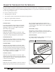


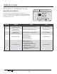


Table Of Contents
- Introduction
- Applications
- Product Overview
- Chassis Features and Benefits
- Ordering Data - EZ Series 42
- Performance Data - EZ Series 42
- Ordering Data - EZ Series DR (DR.PTAC)
- Performance Data - EZ Series DR (DR.PTAC)
- Dr. PTAC Features
- Dr.PTAC information
- Dimensional drawings
- Options and Accessories
- Clearances and Projections
- Installation Instructions
- Wall Sleeve Installation Instructions
- Condensate Drain Kit
- Rear Grille Installation Instructions
- Subbase Assembly & Installation
- Chassis Installation
- Front Cover Installation & Removal
- Fresh Air Vent
- Maintenance
- Information for Heat Pump units
- Electrical Installation
- Wiring Diagram
- System Controls and Management
- Digital Control Panel
- Remote Thermostats
- Remote Thermostat Interface
- Control Board
- Temperature Limiting
- Error Codes
- Performance Specifications
- Warranty

Manufacturer of Quality Air Conditioning and Heating Products • www.islandaire.com • sales@islandaire.com • (800)-886-2759
39
Remote Thermostats
Remote Thermostat
Control
e PTAC unit can be controlled by any remote elec-
tronic thermostat that can interface with RCBWYG ter-
minals. A wiring harness is provided with conductors for
all applications (Heat Cool, Heat Pump, Multispeed Fan,
etc.). See details on the next page. e Control Selection
jumper must be in T’STAT position. During a call, the
remote thermostat will pass R back to the controller on
a respective terminal. e push buttons on the touchpad
become inactive in the remote thermostat mode.
Note: In terms of outputs, there are two types of thermo-
stats: Relay Contacts and Solid State.
Manufacturers of solid state output thermostats include
loading resistors in their installation kits. ese 560
Ohm, 3W resistors are designed to load thermostat solid
state outputs in order for the output voltage to be either
0 or 24 Vac (i.e., no oating voltage). ese resistors are
connected from W, Y, G to common (C), respectively.
You can wire any type of 24 Vac thermostat straight into
the Remote ermostat Interface on the PTAC control
board (see page 40).
Wireless Wall
Thermostat
Wireless wall thermostats are designed to provide precise
temperature control without the installation labor and
expense of wiring.
• Powered by AA batteries
• Mounts in any suitable location that will provide
an accurate room temperature reading.
• Large LCD display provides the user with current
room temperature, set point temperature, time,
program interval, and other system status informa-
tion.
REMOTE CONTROL NODE
Used with a wireless wall thermostat, the RCN commu-
nicates with the thermostat using unlicensed 900 MHz,
radio frequency energy.
Energy Saving Options
Automatic Change-Over Remote Mounted ermostats
can be obtained to switch from heating to cooling and
from cooling to heating automatically. With automatic
change over, the operation of the heating cycle or the
cooling cycle is determined by the temperature require-
ment of the space.
Most thermostats with this feature are set to change over
when the room temperature varies 3-½ °F from the set-
point. e unit is placed in cooling mode when the set-
point is over 3-½ °F; 3-½ °F under the set point places
the unit in the heating mode. is
3-½ °F variation is usually adjustable from a ½ °F dead
band to a 5 °F dead band. Each cycle is run until the
set point temperature is reached, then that cycle is de-
energized. On some thermostats, the automatic change
over function can be overridden manually by moving the
thermostat selector switch to “heat” or to “cool.”
Fan operation with an automatic change over thermostat
is controlled by the fan selector switch. When placed in
the “fan” mode, the fan runs continuously. When placed
in the “auto” mode, the fan will only energize when the
thermostat calls for heating or cooling.