IS2801-4 FEATURES * Current transfer ratio ( CTR : MIN. 50% at IF = 5mA, VCE = 5V ) * Isolation voltage between input and output ( Viso = 3KVrms ) * Compact dual-in-line package 4 channels type * Employs double transfer mold technology * Marked as THP4 * ROHS compliance * G : Halogen Free APPLICATIONS * Hybrid substrates that require high density mounting. * Programmable controllers * System appliances, measuring instruments Part No.
IS2801-4 OUTLINE DIMENSIONS *1. 3-digit date code. *2. Rank shall be or shall not be marked. *3. VDE option Part No.
IS2801-4 TAPING DIMENSIONS Quantities per Reel : Package Type Quantities (pcs) Part No.
IS2801-4 ABSOLUTE MAXIMUM RATING ( Ta = 25°C ) PARAMETER INPUT RATING SYMBOL 217 227 UNIT 247 Forward Current IF 50 mA Reverse Voltage VR 6 V Power Dissipation P 70 mW Collector - Emitter Voltage VCEO 80 V Emitter - Collector Voltage VECO 7 V Collector Current IC 50 mA Collector Power Dissipation PC 150 100 mW Ptot 200 170 mW OUTPUT Total Power Dissipation *1 Isolation Voltage Viso 3,750 Vrms Operating Temperature Topr -55 ~ +110 °C Storage Temperature Tstg
IS2801-4 ELECTRICAL - OPTICAL CHARACTERISTICS ( Ta = 25°C ) PARAMETER INPUT OUTPUT *1 CTR = CONDITIONS Forward Voltage VF — 1.2 1.4 V IF=20mA Reverse Current IR — — 10 μA VR=4V Terminal Capacitance Ct — 30 250 pF V=0, f=1KHz Collector Dark Current ICEO — — 100 nA VCE=50V, IF=0 Collector-Emitter Breakdown Voltage BVCEO 80 — — V IC=0.1mA IF=0 Emitter-Collector Breakdown Voltage BVECO 7 — — V IE=10μA IF=0 IC 2.
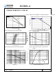
IS2801-4 CHARACTERISTICS CURVES Figure 1. Collector Power Dissipation vs. Ambient Temperature 160 Figure 2. Fo 60 50 120 LTV-217 LTV-227 Forward Current, IF (mA) Collector Power Dissipation, Pc(mW) 140 100 80 LTV-247 60 40 20 40 30 20 10 0 -25 0 25 50 75 100 125 0 Ambient Temperature,Ta(℃) -25 0 25 50 75 100 Ambient Temperature,Ta (℃) Figure 3. Forward Current vs. Forward Voltage -3.
IS2801-4 CHARACTERISTICS CURVES Figure 7. Collector-Emitter Saturation Voltage vs. Forward Current Figure 8. Collector Current vs. Collector-Emitter Voltage 50 5 50mA Collector Currrent, Ic ( mA) 4 3.5 7mA 10mA 5mA 0.5mA 2.5 3mA 3 1mA Collect-Emitt Voltage, VCE (V) 4.5 2 1.5 1 40 30mA 20mA 30 PC(Max)=150mV 20 10mA 10 IF=5mA 0.5 0 0 0 2 4 6 8 10 12 14 16 18 0 20 5 10 Collector-Emitter Voltage, VCE ( V ) Forward Current, IF (mA) Figure 9. Collector Current vs.
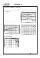
IS2801-4 CHARACTERISTICS CURVES Figure 13. Collector-Emitter Saturation Voltage vs. Ambient Temperature Figure 14. Collector Current vs. Ambient Temperature 0.18 C Collector-Emitter Saturation Voltage (V) 100 0.16 Collector Current, I ( mA ) 0.14 IF=8mA IC=2.4mA 0.12 25mA 20mA 10 0.10 IF=20mA IC=1mA 0.08 5mA IF=1mA IC=0.2mA 0.06 1mA 1 0.04 0.02 IF=0.5mA 0.00 -30 5 40 75 110 o 0.1 -25 0 Ambinet Temperature, Ta ( C) 25 50 75 100 O Ambient Temperature,Ta ( C ) Figure 15.
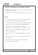
IS2801-4 SWITCHING TIME TEST CIRCUIT TEMPERATURE PROFILE OF SOLDERING REFLOW (1) One time soldering reflow is recommended within the condition of temperature and time profile shown below. Part No.
IS2801-4 TEMPERATURE PROFILE OF SOLDERING REFLOW (2) When using another soldering method such as infrated ray lamp, the temperature may rise partially in the mold of the device. Keep the temperature on the package of the device within the condition of above (1) Notes: - Isocom is continually improving the quality, reliability, function or design and Isocom reserves the right to make changes without further notices.