
User's Manual


How to Install the ISONAS IP-Enabled Reader-controller 7
1.3: INSTALLATION LOCATION GUIDELINES
When selecting the location where you are going to mount the ISONAS reader-
controller, a few guidelines should be observed.
1) The reader-controller should be kept at least 2 feet from another ISONAS
reader-controller, and 6 feet from any other RF emitting device.
2) Assure that the window on the back of the reader-controller’s is mounted
against a reflective surface. A self-adhesive reflective sticker is provided with
each reader-controller, in case the wall’s mounting surface is non-reflective.
Please note that this reflective surface is required for successful operation of
the ISONAS reader-controller
3) In an exterior location, the reader-controller’s mounting should be sealed to
prevent water from running down between the mounting surface and the back
of the reader-controller.
4) For the PowerNet reader, a dielectric insulating compound (Dow Corning DC-4
or equivalent) can be used to obtain extra water protection of the reader-
controller’s cable connections.
5) The reader-controller should be protected from extreme heat and sunlight. It
is rated for conditions up to 120 F. A direct southern exposure, in the
Southwest area of the United States may exceed these ratings.
6) For a few installations, mounting the reader against a large metal object may
reduce the read range of the reader. Steel, iron, and copper will have more of
an effect on the read range than aluminum. If the PowerNet will be mounted
on a steel surface we recommend being prepared to mount a pad ( “1 to 3”
inches in depth) between the reader and the metal frame. Then during the
installation phase and before final mounting of reader test the reader’s read
range to make sure it is acceptable. If not, then insert the pad between the
reader and the steel surface to improve the read range.
7) The cables extending from the back of the PowerNet’s Pigtail cable comes in a
standard 4 ft length. 10 ft and 25 ft lengths Pigtails are optionally available.
Plan for terminating the door wiring within that distance of the reader-
controller.
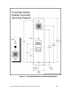
8) The wall mounting features required for the reader-controller are shown in
the next figure. Electronic versions of this figure can be found on the ISONAS
website, and can be printed out, for use as life-size drill templates.