
User's Manual


How to Install the ISONAS PureIP Reader-controller 5
1: BEFORE YOU BEGIN
To install an ISONAS Reader-controller unit, you must complete three key wiring tasks:
1.1. Mount the PureIP reader in the appropriate location. Recommended locations and wiring
methods shall be in accordance with the National Electrical Code, ANSI/NFPA 70.
1.2. Supply power to the PureIP reader. This may be accomplished with power being provided
on the Ethernet data cable (Power over Ethernet [POE / POE+) or through an external DC
power source (12VD). When powering from POE or POE+, in order for the system to be
UL294 V6 compliant, the Power Sourcing Equipment (PSE) injector or end point must be
compliant to UL294 or UL294B standards.
1.3. Wire the unit to the door’s locks and other components for physical access control.
1.4. Connect the unit to the data network for communication with the server/workstation host
PC.
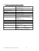
1.5. The PureIP reader complies with UL 294 V6 and is rated for the following performance
levels:
1.5.1. Standby power = Level I.
1.5.2. Endurance = Level IV.
1.5.3. Line Security = Level IV.
1.5.4. Destructive Attack = Level TBD.
This guide discusses each wiring process separately. Understanding all of these processes
makes a project much simpler and helps guarantee success.
1.1: GENERAL REQUIREMENTS:
If PoE is not being used, then use only UL-listed, access control, power-limited power
supplies with an ‘AC on’ indicator light clearly visible on the enclosure. Power supplies should
provide at least four hours of standby power.
Never connect power supplies to a switch-controlled receptacle.
Install the ISONAS system in accordance with the National Electrical Code NFPA 70. (Local
authority has jurisdiction.)
Use only UL-listed wire or cabling recognized suitable for ISONAS power supply and data
communications, in accordance with the National Electrical Code.
Where possible, separate ISONAS equipment and cabling from sources of electromagnetic
interference (EMI). Where this is not possible, take other steps to reduce the effect of EMI on
cabling or equipment.
Protect input and output terminals adequately from transient signals. Also, connect these
terminals to power-limited circuitry.