IMPORTANT SAFETY INSTRUCTIONS! Please read this very carefully before operating this unit Read ALL instructions carefully before using this unit. Do not operate this unit near water, in the rain, or where there is moisture. If this warning is ignored a serious electrical shock or death may occur. Do not attempt to service this unit. No user serviceable parts inside. Refer servicing to qualified, ISP approved service personnel.
INTRODUCTION Thank you for your purchase of the ISP Technologies High Definition Distributed System CS651 Ceiling Speaker. This product provides a new level of performance in distributed audio systems allowing greater system flexibility and easy installation of distributed sound. All connections are made via Cat5 RJ45 connections making installation of systems faster and easier using the CS651. PRECAUTIONS NOTE: IT IS VERY IMPORTANT THAT YOU READ THIS SECTION TO PROVIDE YEARS OF TROUBLE FREE USE.
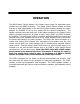
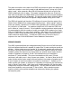
OPERATION The HDDS Master Control Module is the Master control center for distributed sound systems using the HDDS technology. The Master Control Module includes six zones that can be used independently or can be linked to work together allowing the system designer the flexibility to set up any system with the desired configuration.
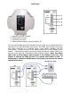
Rear Panel 1. 2. 3. 4. Remote Level RJ45 Connector Output RJ45 Connector Input RJ45 Connector External Power Adaptor Connector 18VAC 1.5A The rear panel includes three RJ45 connectors one for input, one for output and one for connection to an external Remote Level control. The CS651 also includes a power jack that allows connection to an external 18VAC power adaptor available from ISP Technologies. Connect the input to the output connector on a HDDS Master Control Module.
The power connection on the back of the CS651 can be used to power the speaker as a stand-alone speaker or can also be used to add additional power if a long run of Cat5 cable is used. When powered a Blue LED will illuminate behind the front grill of the CS651 indicating the unit is active. The system is designed to allow use of both the Cat5 cable connected to the HDDS Master Control Module and also an external adaptor at the same time without risk of damage.
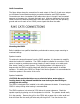
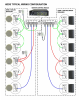
Cat5 Connections The figure below shows the connections for each output A, B and C of each zone output on the Master Control Module and also connections between each CS651 speaker. Connections are done via standard Cat5 cables where pins 1 through 8 are connected common to the same pins 1 through 8 at each end. As shown below two wires in the Cable are used for balanced audio and 6 wires are used for power with two providing ground and two for each of two 22VAC power signals fed down the cable.
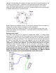
clamps on the back side of the speaker and push downward on the plastic clamp to pop the front grill off the CS651. Connect the Cat5 input cable and Cat5 output cable if series connecting multiple speakers. If using the remote level port on the CS651 connect the Cat5 cable to this port at this time. Insert the CS651 into the opening with the plastic clamps turned in as shown below. Begin to tighten the installation screws.
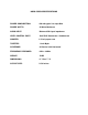
HDDS CS651 SPECIFICATIONS POWER CONSUMPTION: 400 mA typical 1.8 amps Max POWER WATTS: 30 Watts Maximum AUDIO INPUT: Balanced 50k input impedance LEVEL CONTROL PORT: Cat5 RJ45 Connection / Unbalanced WOOFER: 6.
WARRANTY AND SERVICE The unit, parts and workmanship are fully guaranteed to be free of defects under normal use and service for a period of 3 years from the date of purchase. Any damage resulting from the misuse or the failure to follow the precautions and instructions will void the warranty. In the event that the unit needs to be repaired, please return the unit to ISP Technologies directly.