
Owner manual

When properly used, the Decimator ProRack G should be completely transparent, it
should have no effect on the audio signal other than to remove the background
noise. To maximize the performance of the Decimator, it is necessary to understand
both the operation of the controls and the principles of how the internal circuit
operates. After this understanding, it will be easier to set up the Decimator ProRack
G to suit any application.
Principles of the Decimator ProRack G operation:
The Decimator achieves noise reduction by employing two individual noise reduction
processes, which work cohesively together to attain superior results. These two
processes are:
1. Dynamic Low Pass Filtering
2. Low Level Downward Expansion
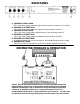
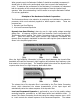
Dynamic Low Pass Filtering is done by use of a high quality voltage controlled
sliding filter. A frequency sensitive audio level detection circuit incorporating ISP
Technologies patent pending Time Vector Processing circuit controls the dynamic
filter. When the audio input signal contains high frequency information the
dynamic filter increases in bandwidth to allow the audio signal to pass unaltered and
shown in the simplified graph below.
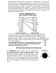
When the high frequency information in the input signal decreases the dynamic filter
bandwidth will track the decrease in high frequency and eliminate high frequency noise
that remains in the input signal. The simplified graph below shows the dynamic filter
response when there is no high frequency audio above 1KHz.
The release time of the dynamic filter is controlled by the Time Vector Processing
circuit, which determines the release characteristics of the input signal and
automatically varies the release response of the dynamic filter.
Low Level Downward Expansion is performed by use of a high quality voltage
controlled amplifier controlled by an RMS based audio level detection circuit. A
second Time Vector Processing circuit that varies the release response over a 1000
to 1 ratio controls the release response of the Downward Expander. The release