INTRODUCTION The Decimator ProRack noise reduction system defines a new standard for excellence in real time noise reduction performance. The Decimator ProRack was designed to provide the maximum possible performance in a rack mount dual channel noise reduction system. The Decimator ProRack has dual processing channels incorporating both low-level downward expansion and dynamically controlled low-pass filtering in a very easy to use single rack space unit.
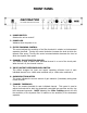
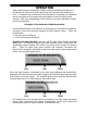
FRONT PANEL 1. POWER SWITCH Switches the unit on and off. 2. POWER LED Indicates when the power is on. 3. FILTER TRACKING CONTROL This control adjusts the sensitivity of the filter threshold in relation to the downward expander threshold. Turning this control clockwise increases the level at which the dynamic filter opens. Turning this control counterclockwise decreases the level at which the dynamic filter opens. 4.
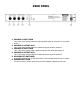
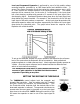
REAR PANEL 1. CHANNEL 1 INPUT JACK This ¼ inch mono jack provides the high impedance input for connection to your audio device. 2. CHANNEL 1 OUTPUT JACK This ¼ inch mono jack provides the unbalanced output signal for channel 1. 3. CHANNEL 2 INPUT JACK This ¼ inch mono jack provides a balanced input for the audio path channel 2. 4. CHANNEL 2 OUTPUT JACK This ¼ inch mono jack provides the unbalanced output signal for channel 2. 5.
OPERATION When properly used, the Decimator ProRack should be completely transparent, it should have no effect on the audio signal other than to remove the background noise. To maximize the performance of the Decimator, it is necessary to understand both the operation of the controls and the principles of how the internal circuit operates. After this understanding, it will be easier to set up the Decimator ProRack to suit any application.
Low Level Downward Expansion is performed by use of a high quality voltage controlled amplifier controlled by an RMS based audio level detection circuit. A second Time Vector Processing circuit that varies the release response over a 1000 to 1 ratio controls the release response of the Downward Expander. The release response will be extremely fast, on the order of 2 milliseconds, if the input signal has a fast decaying envelope and upwards of 2 seconds if the input signal has a slow decaying signal.
SETTING THE FILTER TRACKING CONTROL The FILTER TRACKING control adjusts the relationship between the sensitivity of the Dynamic Filter and the Expander. Once the THRESHOLD control is set for proper operation of the downward expander increase the FILTER TRACKING control until the desired dynamic filter operation is achieved. Setting this control to high will cause the filter to not fully open when high frequency signals are present.
WARRANTY AND SERVICE The unit, parts and workmanship are fully guaranteed to be free of defects under normal use and service for a period of 2 years from the date of purchase. Any damage resulting from the misuse or the failure to follow the precautions and instructions will void the warranty. In the event that the unit needs to be repaired, please return the unit to ISP Technologies directly.