INTRODUCTION Congratulations on your purchase of the THETA Head. You are now the owner of the most innovative guitar amplifier ever produced. The THETA Head was designed to provide the maximum possible over the top performance.
FRONT PANEL Understanding the THETA amplifier 6. POWER SWITCH Switches the unit on and off. 7. POWER LED THETA PREAMP1 1. PREAMP1 ON LED This led indicates when PREAMP1 is active and in the signal path. NOTE: The PREAMP1 switch on the THETA FOOTCONTROLLER switches PREAMP1 on and off. PREAMP1 is functional only when the CLEAN channel is selected. PREAMP1 and PREAMP2 will automatically switch with the channel selected. 2.
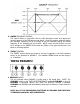
5. SWEEP FREQUENCY CONTROL This control works in conjunction with the MID boost/cut control and adjusts the center frequency of the MID boost or cut signal. At the full counter clockwise setting the midrange frequency will be at 300Hz, at the full clockwise setting the center frequency of the midrange will be at 6KHz. NOTE: when the MID control is set at 12:00 straight up the SWEEP will not have any affect on the signal since there is not boost or cut being applied. 6.
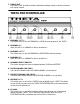
THETA CLEAN CHANNEL 1. CLEAN CHANNEL ON LED This led indicates when the CLEAN CHANNEL is active. NOTE: The CHANNEL SELECT switch on the THETA FOOTCONTROLLER switches between the CLEAN CHANNEL and DISTORT CHANNEL. THE CLEAN can be selected by using either the THETA FOOTCONTROLLER CHANNEL SELECT switch or by pushing the CHANNEL SELECT switch on the from panel of the THETA amplifier. 2. PRESENCE CONTROL This control adjusts the amount of high frequency presence in the CLEAN channel.
5. SWEEP FREQUENCY CONTROL This control works in conjunction with the MID boost/cut control and adjusts the center frequency of the MID boost or cut signal. At the full counter clockwise setting the midrange frequency will be at 300Hz, at the full clockwise setting the center frequency of the midrange will be at 6KHz. NOTE: when the MID control is set at 12:00 straight up the SWEEP will not have any affect on the signal since there is not boost or cut being applied. 6.
9. LEVEL CONTROL The LEVEL control adjusts the output LEVEL of the CLEAN channel. NOTE: The final output level is determined by the setting of the MASTER LEVEL CONTROL. THETA DISTORT CHANNEL 1. CHANNEL SELECT SWITCH The CHANNEL SELECT switch changes the THETA operating channel from CLEAN to DISTORT. The CHANNEL SELECT switch is a momentary switch that changes the channel upon pushing the switch. This switch can be used with or without the THETA FOOTCONTROLLER connected. 2.
6. SWEEP FREQUENCY CONTROL This control works in conjunction with the MID boost/cut control and adjusts the center frequency of the MID boost or cut signal. At the full counter clockwise setting the midrange frequency will be at 300Hz, at the full clockwise setting the center frequency of the midrange will be at 6KHz. NOTE: when the MID control is set at 12:00 straight up the SWEEP will not have any affect on the signal since there is not boost or cut being applied. 7.
2. EFFECTS LEVEL CONTORL This control adjusts the level of an externally connected effects processor. NOTE: The loop must be turned on via the THETA FOOTCONTROLLER in order for the EFFECTS level to operate. 3. SOLO LEVEL This control adjusts the amount of boost that will be applied to the output signal when the THETA FOOTCONTROLLER boost switch is activated. This control allows the user to switch on and off via the THETA FOOTCONTROLLER up to 6db of output level boost if desired for soloing. 4.
7. DIRECT OUT The DIRECT OUT provides a speaker simulated recording output for direct connection to a mixing console. THETA FOOTCONTROLLER 1. PREAMP1 SWITCH This switch turns on and off PREAMP1 the CLEAN channel preamp on the THETA. 2. PREAMP1 LED When this LED in on PREAMP1 is active, switched on. 3. PREAMP2 SWITCH This switch turns on and off PREAMP2 the DISTORTION channel preamp. 4. PREAMP2 LED When this LED in on PREAMP2 is active, switched on. 5.
10. BOOST This switch turns on and off the THETA BOOST function allowing up to 6db of boost of the output level of the amplifier. 11. D-SUB CONNECTOR Connect the 15-pin D-SUB connector between this connector and the D-SUB connector on the back of the THETA amplifier. FUSE REPLACEMENT 1. Use a small screwdriver as shown to slide the fuse cover out from the power inlet module. The fuse can be found inside the fuse cover module after it is pulled out.
THETA SPECIFICATIONS Input Impedance Maximum Gain in Distortion channel Treble Control /Preamp 1 and 2 Treble Control /Clean and Distort Bass Control /Preamp 1 and 2 Bass Control /Clean and Distort Mid Sweep Frequency /Preamps Mid Sweep Frequency /Channels Mid Boost/Cut Range /Preamps Mid Boost/Cut Range /Channels Presence Range (Clean Channel) Decimator Effective Noise Reduction Digital Reverb bandwidth D-CAT amplifier output power D-CAT amplifier protection Boost Level Direct recording output level THETA
WARRANTY AND SERVICE The Internal Circuitry is fully guaranteed to be free of defects under normal use and service for a period of three years from the date of purchase. The Speakers and Cabinet that are used in this product are fully guaranteed to be free of defects under normal use and service for a period of three years. Any damage resulting from the misuse or the failure to follow the precautions and instructions will void the warranty.