IMPORTANT SAFETY INSTRUCTIONS! Please read this very carefully before operating this unit Read ALL instructions carefully before using this unit. Do not operate this unit near water, in the rain or where there is moisture. If this warning is ignored a serious electrical shock or death may occur. Do not attempt to service this unit. No user serviceable parts inside. Refer servicing to qualified, ISP approved service personnel.
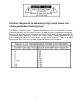
Caution: Exposure to extremely high noise levels can cause permanent hearing loss. The XMAX112 speaker system is capable of producing in excess of 136db SPL at 1 meter. Continued exposure to noise levels in excess of 90db may cause permanent hearing loss. Below is a chart of the OSHA (Occupational Safety & Health Administration) regulations for Occupational Noise Exposure.
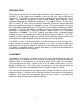
INTRODUCTION Thank you for purchasing ISP Technologies XMAX112 active subwoofer system. The XMAX112 is a high output active subwoofer system for high SPL sound reinforcement applications. The XMAX112 was designed with a 500-watt 12-inch woofer that is horn loaded. The XMAX112 incorporates a High Current D-CAT power amplifier system capable of producing over 1000 watts RMS power.
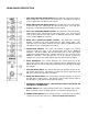
REAR PANEL DESCRIPTION 1. LEFT HIGH PASS BALANCED OUTPUT- This XLR male connector provides a balanced high pass output from the left channel input. The high pass frequency is set at 100 Hz with a 24 dB per octave roll off. 2. RIGHT HIGH PASS BALANCED OUTPUT- This XLR male connector provides a balanced high pass output from the right channel input. The high pass frequency is set at 100 Hz with a 24 dB per octave roll off. 3.
FUSE REPLACEMENT 1. Use a small screwdriver as shown to slide the fuse cover out from the power inlet module. The fuse can be found inside the fuse cover module after it is pulled out. NOTE: A SMALL COMPARTMENT IS ALSO PROVIDED WITHIN THE FUSE COVER MODULE FOR STORING A SPARE FUSE. 2. After replacing the fuse with another of identical specifications, push the fuse cover module fully back into place, ensuring that the fuse has snapped onto the fuse holder inside the power inlet module.
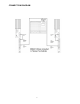
CONNECTION DIAGRAM 7
BALANCED CONNECTION DESCRIPTION The ISP Sub Series has balanced XLR and inputs and outputs configured to AES standards (Audio Engineering Society). These connections are connected in a loop through configuration from the inputs to the full range outputs and will accept a balanced line-level input. The standard phase configuration is that pin 2 is (+), pin 3 is (-), and pin 1 is shielded ground on the XLR.
SPECIFICATIONS System Frequency Range Frequency Response (-3dB) Peak Output @ 1m Crossover Point Input Type Input Impedance Thermal Protection Transducer Low-Frequency Transducer Diameter Voice Coil Diameter Power Handling 35Hz - 300Hz 41Hz - 100Hz 133 dB SPL 100Hz (24db per Octave) Balanced differential 10K ohms Output Drivers have internal protection, self resetting. Heatsink temperature monitored and input is muted if safe temperature is exceeded, self-resetting.
THERMAL CONDITIONS The ISP XMAX112 Sub Series is capable of producing 1000 watts at full power. This generates heat that must be dissipated in order to maintain reliability and insure the amplifier components stay within their operating temperature specs. To accomplish this, the amplifier is mounted onto a heatsink that requires air movement at the rear of the cabinet.
WARRANTY AND SERVICE The Internal Circuitry is fully guaranteed to be free of defects under normal use and service for a period of three years from the date of purchase. The Speakers and Cabinet that are used in this product are fully guaranteed to be free of defects under normal use and service for a period of three years. Any damage resulting from the misuse or the failure to follow the precautions and instructions will void the warranty. In the event that the unit needs to be repaired.