
Install Instructions
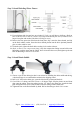
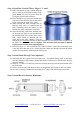
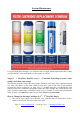
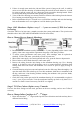
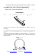

Table Of Contents
- How to Use Quick-connect Fitting
- How to Use Compression Fitting with Brass Nut, Collar, and Tube Insert
- How to Drill a Hole in Sink or Counter-top
- Ice Maker Kit
- Step 1: Install Feed Water Adapter (AFW)
- Step 2: Install Drinking Water Faucet
- Step 3: Install Drain Saddle
- Step 4: Install the Vertical Filters: Stages 1, 2, and 3
- Step 5: Install Tank Shut-off Valve (Optional)
- Step 6: Install Reverse Osmosis Membrane
- Step 7: Tubing Hook Up (optional sub-steps are marked with * )
- Step 8: System Start Up (optional sub-steps are marked with * )
- Stages 1 – 3 Pre-filters: Replace every 6 – 12 months, depending on source water quality and clean water usage.
- How to Change In-housing Cartridges in 1st – 3rd Pre-filter Stages
- Stage 4 RO Membrane: Replace every 2 – 3 years or sooner if TDS level starts increasing.
- How to Change Reverse Osmosis Membrane
- Stage 5 T33 Fine Carbon: Replace every 12 months
- How to Change Inline Cartridges in 5th – 7th Stages
- O-rings: Replace every 3 years or sooner if leak happens at O-ring.
- UV Lamp (part# iSpring UVF11A) and Ice Maker Kit (part# iSpring ICEK)
- 空白页面

Page 11 www.123filter.com | (678) 261-7611 | support@123filter.com
6.1 Open the membrane housing cap. A thick rubber band can be slipped on the housing body
for better grip.
6.2 Find the inner end with 4 O-rings, cut open the end of sealed bag and use it to hold RO
membrane to avoid contamination, and firmly insert the membrane into the housing until
the outer end with only 2 O-rings is completely inside the housing. See Figure above.
6.3 Before twisting the housing cap back on, check that the O-ring is evenly snagged on the
membrane housing (cap does NOT have O-ring). Hang tight and tighten up for about 1/4
– 1/2 turns using a small plastic housing wrench, but do not over tighten. DO NOT
reconnect the tubing to inlet on cap at this point (will do it in system start up).
Step 7: Tubing Hook Up (optional sub-steps are marked with * )
7.1 Facing the iSpring logo up front, locate the pre-filter 1
st
stage on the right hand side.
Connect the 3/8” tubing between Feed Water Adapter (AFW) and point A.
7.2 Connect the Flow Restrictor (point C) , which is a 3” long cylinder with a FLOW sign
laying beside the membrane housing, to the black Drain Saddle with 1/4” tubing.
7.3 Connect the Post Carbon Filter FT15 5
th
stage (point B) to the RO faucet with 1/4” tubing.
* If you have a RO storage tank, replace the elbow fitting at point D with a Tee fitting, reconnect
the tubing from the check valve to one T, and connect the other T with tank shut-off valve.