
User Manual


ISSPRO, INC. 2515 N.E. Riverside Way, Portland OR 97211
Telephone: (503) 288-4488 Toll Free: (800) 888-8065
FAX: (503) 249-2999
ISSPRO 118mm and 5” Programmable Speedometer
Microprocessor Aircore Version
GENERAL INFORMATION:
Operating Voltage: 11 – 16 VDC
Input: Magnetic sensor or AC generator
Transient Protection: +100 V, -400 V
Reverse Voltage Protected
CALIBRATION:
The ISSPRO Programmable Speedometer is calibrated (programmed) by setting a combination of ten switches
found in the rear of the instrument. The odometer and pointer are electronically linked together and both are
calibrated when the switches are properly set. Program before installing.
Note: the switch setting must be done with power “off”. If power is left “on”, changing the switch will have no
effect on calibration until power is interrupted.
CALIBRATION PROCEDURE:
Calculate the "calibration number" from the appropriate formula below. (A minimum calibration number of 14820
is required to be within calibration range). Refer to the "CALIBRATION SWITCH SETTING" table with this
number. Locate the row in which the calibration number is between the limits, then set the switches marked with
an "0" to the "on" position (up).
EXAMPLE: Calibration number = 29644: From the table 29644 lies between 29580 and 29699, therefore,
switches 4, 9, and 10 will be set to "on".
(1) Front wheel mounted tone wheel:
Calibration Number = # Slots in Tone Wheel X
Tire Revs per Mile
(2) Tail Shaft mounted magnetic sensor:
Calibration Number = Tire Revs per Mile X
Differential Ratio X 16
(3) Sender driven from transmission cable drive:
Calibration Number = Cable Turns Per Mile x
#Pulses per Sender Turn
Note: For metric versions, substitute kilometers for
miles in the above formulas. Multiply the resulting
value by 0.621 to obtain final calibration number.
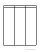
1 2 3 4 5 6 7 8 910
Back of Can
Dip Switch
Access Hole
Connector Wires
Grommet
On
On
Form IS120 (Rev C 10/25/2012) Page 1 of 7