
Data Sheet

HYGROCHIP
1/3
DIGITAL HUMIDITY SENSOR
PROTOCOL DESCRIPTION I2C
I
2
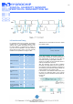
C Interface and Timing
For integration with a micro-controller, the humidity
module has an I
2
C-compatible interface which
supports both 100kHz and 400kHz bit rates. The
I
2
C slave address is programmed by default on
0x28 and can be adjusted in the entire address
range (0x00 to 0x7F). Hence, up to 126 humidity
modules can be operated on a single I
2
C-Bus.
PARAMETER SYMBOL MIN MAX UNIT
SCL clock frequency fSCL 100 400 kHz
Start condition hold time
relative to SCL edge
tHDSTA 0.1 4s
Minimum SCL clock low
width 1
tLOW 0.6 4s
Minimum SCL clock
high width 1
tHIGH 0.6 4s
Start condition setup
time relative to SCL
edge
tSUSTA 0.1 4s
Data hold time on SDA
relative to SCL edge
tHDDAT 0 4s
Data setup time on SDA
relative to SCL edge
tSUDAT 0.1 4s
Stop condition setup
time on SCL
tSUSTO 0.1 4s
Bus free time between
stop condition and start
condition
tBUS 1 4s
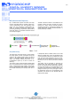
There are two I
2
C commands for the user to access
the humidity module:
Command Description
'Data Fetch' (DF) Fetch the last measured value of
Humidity / Temperature
'Measuring Request' (MR) Start a measuring cycle
In the initial condition, the humidity module is in
sleep mode to minimize the current consumption. A
new measurement is carried out only after the
command measuring request (MR) is received.
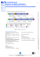
Access to the status bits and measured values is
made by the data fetch command.
After the measuring cycle has been completely
processed, the ready status bit is set and the cur-
rent measured values are available. To determine if
the measuring cycle has been already finished, the
output registers may be cyclically polled.
If the access to the measured values takes place
too early, the measured values of the previous
measuring cycle are transferred and the stale sta-
tus bit is set.