HOME SECTION 0A 0B WORKSHOP MANUAL 1A 2A AXIOM (UPR/S) 3C 3D 3E 3F 4A1 4A2 4B1 4B2 4C 4D2 FOREWORD This manual includes special notes, important points, service data, precautions, etc. That are needed for the maintenance, adjustments, service, removal and installation of vehicle components. All information, illustrations and specifications contained in this manual are based on the latest product information available at the time of publication.
SECTION GENERAL INFORMATION 0A–1 AXIOM GENERAL INFORMATION CONTENTS General Information . . . . . . . . . . . . . . . . . . . . . Maintenance and Lubrication . . . . . . . . . . . . . 0A 0B General Information CONTENTS General Repair Instruction . . . . . . . . . . . . . . . . Illustration Arrows . . . . . . . . . . . . . . . . . . . . . . . Identification . . . . . . . . . . . . . . . . . . . . . . . . . . . . Theft Prevention Standard . . . . . . . . . . . . . . . .
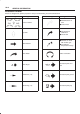
0A–2 GENERAL INFORMATION Illustration Arrows Arrows are designed for specific purposes to aid your understanding of technical illustrations.
GENERAL INFORMATION Identification Vehicle Identification Number (VIN) This is the legal identification of the vehicle. it is located on the left bottom of the windshield. It can be easily seen through the windshield from outside the vehicle.
0A–4 GENERAL INFORMATION Engine Serial Number The gasoline engine serial number is stamped on the left rear lower area of the cylinder block above the starter. 240R200014 Automatic : Stamped on the identification plate, located on the left side of the transmission above the mode switch.
GENERAL INFORMATION 0A–5 Theft Prevention Standard The 11 major components listed below will be marked with 17 digit VIN at the stage of production. In addition its service parts will be marked with manufacturer’s trade mark, “R” mark and “DOT” mark. Reference Figure No.
0A–6 GENERAL INFORMATION Anti Theft Stamping/Label/Plate Location The stamping, label and plate locations are indicated by arrows in the illustration below. NOTE: 1. VIN plate locations for production. 2. Stamping locations for service parts.
GENERAL INFORMATION 0A–7 Body 604R200007
0A–8 GENERAL INFORMATION Body Label Instructions Do not peel off the masking tape until completion of paint work when replacing these parts, as the tape is affixed on the label attached to service parts for body of the anti–theft component. NOTE: Be sure to pull off the masking tape after paint work has been completed. Do not attempt to remove this label for any reason. 901RW083 Precautions in pulling off the masking tape 1.
GENERAL INFORMATION 0A–9 Lifting Instructions CAUTION: B If a lifting device other than the original jack is used, it is most important that the device be applied only to the correct lifting points. Raising the vehicle from any other point may result in serious damage. B When jacking or lifting a vehicle at the frame side rail or other prescribed lift points, be certain that lift pads do not contact the catalytic converter, brake pipes or cables, or fuel lines.
0A–10 GENERAL INFORMATION Supportable Point: Front Supportable Point: Rear B Position the chassis stands at the bottom of the frame sidemember, behind the front wheel. B Position the chassis stands at the bottom of the frame sidemember, just behind the trailing link bracket. 501RS003 Lifting Point: Rear B Position the floor jack at the center of the rear axle case when lifting the vehicle.
GENERAL INFORMATION 0A–11 Standard Bolts Torque Specifications The torque values given in the following table should be applied where a particular torque is not specified. Strength Class 8.8 4.8 Refined 9.8 Non-Refined Bolt Identification Bolt Diameter × Pitch (mm) M 6X1.0 M 8X1.25 M 10X1.25 * M10X1.5 M12X1.25 * M12X1.75 M14X1.5 * M14X2.0 M16X1.5 * M16X2.0 M18X1.5 M20X1.5 M22X1.5 M24X2.
0A–12 GENERAL INFORMATION Abbreviations Charts List of automotive abbreviations which may be used in this manual A — Ampere(s) ABS — Antilock Brake System AC — Alternating Current A/C — Air Conditioning ACCEL — Accelerator ACC — Accessory ACL — Air Cleaner Adj — Adjust A/F — Air Fuel Ratio AIR — Secondary Air Injection System Alt — Altitude AMP — Ampere(s) ANT — Antenna ASM — Assembly A/T — Automatic Transmission/Transaxle ATDC — After Top Dead Center ATF — Automatic Transmission Fluid Auth — Authority Au
GENERAL INFORMATION N — Newtons NA — Natural Aspirated NC — Normally Closed N·M — Newton Meters NO — Normally Open NOX — Nitrogen, Oxides of OBD — On-Board Diagnostic OD — Outside Diameter O/D — Over Drive OHC — Overhead Camshaft OL — Open Loop O2 — Oxygen O2S — Oxygen Sensor PAIR — Pulsed Secondary Air Injection System P/B — Power Brakes PCM — Powertrain Control Module PCV — Positive Crankcase Ventilation PRESS — Pressure PROM — Programmable Read Only Memory PNP — Park/Neutral Position P/S — Power Steering
SECTION MAINTENANCE AND LUBRICATION 0B–1 AXIOM GENERAL INFORMATION Maintenance and Lubrication CONTENTS Maintenance Schedule List . . . . . . . . . . . . . . . Explanation of Complete Vehicle Maintenance Schedule . . . . . . . . . . . . . . . . . . . . . . . . . . . . . . Recommended Fluids and Lubricants . . . . Lubricant Viscosity Chart . . . . . . . . . . . . . . . . . 0B–1 0B–5 0B–8 0B–9 Recommended Liquid Gasket . . . . . . . . . . . Recommended Thread Locking Agents . . .
0B–2 MAINTENANCE AND LUBRICATION Mileage Only Items
MAINTENANCE AND LUBRICATION Mileage/Months 0B–3
0B–4 MAINTENANCE AND LUBRICATION
MAINTENANCE AND LUBRICATION Explanation of Complete Maintenance Schedule Vehicle 0B–5 Radiator Core and Air Conditioning Condenser Cleaning Brief explanations of the services listed in the preceding Maintenance Schedule are presented below. Replace all questionable parts and note any necessary repairs as you perform these maintenance procedures. Clean the front of the radiator core and air conditioning condenser, at 60,000 miles (96,000 km) intervals.
0B–6 MAINTENANCE AND LUBRICATION Always change the oil and the oil filter as soon as possible after driving in a dust storm. Engine Cooling System Inspection Inspect the coolant/anti–freeze. If the coolant is dirty or rusty, drain, flush and refill with new coolant. Keep coolant at the proper mixture for proper freeze protection, corrosion inhibitor level and best engine operating temperature. Inspect hoses and replace if cracked, swollen or deteriorated.
MAINTENANCE AND LUBRICATION Automatic Transmission Fluid Replacement Under harsh operating conditions, such as constant driving in heavy city traffic during hot weather, or in hilly or mountainous terrain, change the transmission fluid and service the sump filter after every 20,000 miles (32,000 km) of operation. More over, the remaining life percentage of ATF can be estimated by using TECH–II as an auxiliary tool to judge the right time for ATF replacement.
0B–8 MAINTENANCE AND LUBRICATION Recommended Fluids and Lubricants USAGE Engine FLUID/LUBRICANT API SE, SF, SG, SH or ILSAC GF-1 Engine oil (See oil chart on the following page for proper viscosity) Engine coolant Mixture of water and good quality ethylene glycol base type antifreeze. Brake system DOT-3 hydraulic brake fluid. Power steering system DEXRON -III Automatic transmission fluid. Automatic transmission DEXRON -III Automatic transmission fluid.
MAINTENANCE AND LUBRICATION 0B–9 Lubricant Viscosity Chart Lubricants should be carefully selected according to the lubrication chart. It is also important to select viscosity of lubricants according to the ambient temperature by referring to the following table.
0B–10 MAINTENANCE AND LUBRICATION Oil Viscosty Chart for Rear Axle B00RW004
MAINTENANCE AND LUBRICATION 0B–11 Recommended Liquid Gasket Type Brand Name Manufacturer Remarks Three Bond Three Bond Three Bond Three Bond Three Bond For Engine Repairs RTV* Silicon Base Three Bond 1207B Three Bond 1207C Three Bond 1215 Three Bond 1280 Three Bond 1281 Water Base Three Bond 1141E Three Bond For Engine Repairs Solvent Three Bond 1104 Belco Bond 4 Belco Bond 401 Belco Bond 402 Three Bond Isuzu Isuzu Isuzu For Engine Repairs Anaerobic LOCTITE 515 LOCTITE 518 LOCTITE 17430
0B–12 MAINTENANCE AND LUBRICATION Maintenance Service Data Service Data and Specifications Valve clearance (cold) Intake 0.28±0.05 mm (0.011±0.002 in) Exhaust 0.3±0.05 mm (0.012±0.002 in) Spark plug type K16PR-P11/PK16PR11/RC10PYP4 Spark plug gap 1.05 mm (0.04 in) Brake pedal free play 6–10 mm (0.24–0.39 in) Parking brake travel 6–7 notches Toe-in (Front) 0 to +2 mm (0 to +0.08 in) Toe-in (Rear) 0±5 mm (0±0.
SECTION HEATING, VENTILATION AND AIR CONDITIONING (HVAC) 1A–1 AXIOM HEATING, VENTILATION AND AIR CONDITIONING (HVAC) HVAC SYSTEMS CONTENTS Service Precaution . . . . . . . . . . . . . . . . . . . . . . Heating and Ventilation System . . . . . . . . . . . General Description . . . . . . . . . . . . . . . . . . . . . Heater Unit . . . . . . . . . . . . . . . . . . . . . . . . . . . . . Heater Unit and Associated Parts . . . . . . . . Removal . . . . . . . . . . . . . . . . . . . . . . . . . . . . .
1A–2 HEATING, VENTILATION AND AIR CONDITIONING (HVAC) Compressor . . . . . . . . . . . . . . . . . . . . . . . . . . . . Service Precaution . . . . . . . . . . . . . . . . . . . . General Description . . . . . . . . . . . . . . . . . . . . . . Diagnosis . . . . . . . . . . . . . . . . . . . . . . . . . . . . . Magnetic Clutch Assembly (DKV-14G Type) Parts Location View . . . . . . . . . . . . . . . . . . . . Removal . . . . . . . . . . . . . . . . . . . . . . . . . . . . . Inspection and Repair . . . . .
HEATING, VENTILATION AND AIR CONDITIONING (HVAC) Service Precaution WARNING: THIS VEHICLE HAS A SUPPLEMENTAL RESTRAINT SYSTEM (SRS). REFER TO THE SRS COMPONENT AND WIRING LOCATION VIEW IN ORDER TO DETERMINE WHETHER YOU ARE PERFORMING SERVICE ON OR NEAR THE SRS COMPONENTS OR THE SRS WIRING. WHEN YOU ARE PERFORMING SERVICE ON OR NEAR THE SRS COMPONENTS OR THE SRS WIRING, REFER TO THE SRS SERVICE INFORMATION.
1A–4 HEATING, VENTILATION AND AIR CONDITIONING (HVAC) 840R200007 Legend (1) Defroster Nozzle (2) Ventilation Duct (3) Blower Assembly (4) (5) (6) (7) Evaporator Assembly Ventilation Lower Duct Heater Unit Rear Heater Duct
HEATING, VENTILATION AND AIR CONDITIONING (HVAC) 1A–5 C01RW001 Air Source Select Switch Temperature Control Switch Press this button to select either Fresh Air Intake or CIRC (inside air circulation). There is an indicator light inside the button. This light indicates that the CIRC mode is “ON”. Fresh Air Intake is the default setting for both DEFROST and FOOT/DEFROST.
1A–6 HEATING, VENTILATION AND AIR CONDITIONING (HVAC) Heater Unit Heater Unit and Associated Parts 840R200008 Legend (1) Instrument Panel Assembly (2) Cross Beam Assembly (3) Instrument Panel Bracket W/Suspension Control Unit (4) Ventilation Lower Duct Removal 1. Disconnect the battery ground cable. 2. Drain the engine coolant. 3. Discharge and recover refrigerant (with air conditioning). B Refer to Refrigerant Recovery in this section. 4. Remove the Instrument panel assembly.
HEATING, VENTILATION AND AIR CONDITIONING (HVAC) 1A–7 2. When installing the heater unit, defroster nozzle and center vent duct, be sure that the proper seal is made, without any gap between them.
1A–8 HEATING, VENTILATION AND AIR CONDITIONING (HVAC) 11. Pull out the mode door while raising up the catch of the door lever. Removal 1. Disconnect the battery ground cable. 2. Drain the engine coolant. 3. Discharge and recover refrigerant (with air conditioning). B Refer to Refrigerant Recovery in this section. 4. Remove heater unit. B Refer to Heater Unit in this section. 5. Remove duct. 6. Remove mix actuator. 7. Remove mode actuator. 8.
HEATING, VENTILATION AND AIR CONDITIONING (HVAC) 1A–9 Heater Mode Control Link Unit Disassembled View 860R200002 Legend (1) Case (Mode Control) (2) Heater Unit (3) Mode Sub-lever (4) Clip (5) (6) (7) (8) Door Lever Rod Mode Actuator Washer and Mode Main Lever Removal 1. Disconnect the battery ground cable. 2. Drain engine coolant. 3. Discharge and recover refrigerant (with air conditioning) B Refer to Refrigerant Recovery in this section. 4. Remove heater unit. B Refer to Heater Unit in this section.
1A–10 HEATING, VENTILATION AND AIR CONDITIONING (HVAC) 10. Pull out the door lever while raising up the catch of the door lever. 11. Remove clip. Installation To install, follow the remove steps in the reverse order, noting the following points: 1. Apply grease to the mode sub-lever and to the abrasive surface of the heater unit. 2. After installing the link unit, check to see if the link unit operates correctly.
HEATING, VENTILATION AND AIR CONDITIONING (HVAC) 1A–11 Heater Temperature Control Link Unit Disassembled View 860R200003 Legend (1) Case (Temperature control) (2) Door Lever (3) Clip (4) Rod (5) (6) (7) (8) Clip Sub-lever Mix Actuator Heater Unit Removal Installation 1. Disconnect the battery ground cable. 2. Drain engine coolant. 3. Discharge and recover refrigerant (with air conditioning). B Refer to Refrigerant Recovery in this section. 4. Remove heater unit.
1A–12 HEATING, VENTILATION AND AIR CONDITIONING (HVAC) Blower Assembly Blower Assembly and Associated Parts 873R200004 Legend (1) Instrument Panel Assembly (2) Blower Assembly Removal 1. Disconnect the battery ground cable. 2. Discharge and recover refrigerant (with air conditioning). B Refer to Refrigerant Recovery in this section. 3. Remove instrument panel assembly. B Refer to Instrument Panel Assembly in Body and Accessories section. 4. Disconnect power transistor connector. 5.
HEATING, VENTILATION AND AIR CONDITIONING (HVAC) 1A–13 Blower Link Unit and / or Mode door Disassembled View 873R200001 Legend (1) Blower Assembly (2) Upper Case (3) Mode Door (4) Lower Case (5) (6) (7) (8) Max High Relay Intake Actuator Sub Lever Door Lever Removal 1. Disconnect the battery ground cable. 2. Discharge and recover refrigerant (with air conditioning). B Refer to Refrigerant Recovery in this section. 3. Remove blower assembly. B Refer to Blower Assembly in this section. 4.
1A–14 HEATING, VENTILATION AND AIR CONDITIONING (HVAC) 8. Pull out the mode door while raising up the catch of door lever. 9. Remove sub-lever. 10. Remove door lever. Installation To install, follow the removal steps in the reverse order, noting the following points: 1. Apply grease to the door lever and to the abrasive surface of the upper case. 2. Apply an adhesive to the parting face of the lining when assembling the upper case.
HEATING, VENTILATION AND AIR CONDITIONING (HVAC) 1A–15 Blower Motor Blower Motor and Associated Parts 873RS004 Legend (1) Blower Motor Connector (2) Blower Motor Assembly (3) Clip Removal 1. Disconnect the battery ground cable. 2. Remove blower motor connector. 3. Remove attaching screw. 4. Remove blower motor assembly. 5. Remove clip. 6. Remove fan. 7. Remove blower motor. (4) Fan (5) Blower Motor (6) Attaching Screw Installation To install, follow the removal steps in the reverse order.
1A–16 HEATING, VENTILATION AND AIR CONDITIONING (HVAC) Rear Heater Duct, Defroster Nozzle and Ventilation Duct Rear Heater Duct, Defroster Nozzle, Ventilation Duct and Associated Parts 840R200009 Legend (1) Defroster Nozzle (2) Cross Beam Assembly (3) Center Ventilation Duct and Side Defroster Duct Removal 1. Disconnect the battery ground cable. 2. Remove instrument panel assembly. B Refer to Instrument Panel Assembly in Body and Accessories section. 3.
HEATING, VENTILATION AND AIR CONDITIONING (HVAC) 1A–17 7. Remove rear heater duct. B Remove foot rest carpet and 3 clips. 8. Remove defroster nozzle. Installation To install, follow the removal steps in the reverse order, noting the following point: 1. Connect each duct and nozzle securely leaving no clearance between them and making no improper matching.
1A–18 HEATING, VENTILATION AND AIR CONDITIONING (HVAC) Air Conditioning System General Description Air Conditioning Refrigerant Cycle Construction C01RY00013 Legend (1) Duct Sensor (2) Evaporator Core (3) Evaporator Assembly (4) Temperature Sensor (5) Blower Motor (6) Expansion Valve (7) Pressure Switch (8) Receiver/Drier The refrigeration cycle includes the following four processes as the refrigerant changes repeatedly from liquid to gas and back to liquid while circulating.
HEATING, VENTILATION AND AIR CONDITIONING (HVAC) 1A–19 Evaporation The refrigerant is changed from a liquid to a gas inside the evaporator. The refrigerant mist that enters the evaporator vaporizes readily. The liquid refrigerant removes the required quantity of heat (latent heat of vaporization) from the air around the evaporator core cooling fins and rapidly vaporizes. Removing the heat cools the air, which is then radiated from the fins and lowers the temperature of the air inside the vehicle.
1A–20 HEATING, VENTILATION AND AIR CONDITIONING (HVAC) A condenser may malfunction in two ways: it may leak, or it may be restricted. A condenser restriction will result in excessive compressor discharge pressure. If a partial restriction is present, the refrigerant expands after passing through the restriction. Thus, ice or frost may form immediately after the restriction. If air flow through the condenser or radiator is blocked, high discharge pressures will result.
HEATING, VENTILATION AND AIR CONDITIONING (HVAC) 1A–21 The expansion valve regulates the flow rate of the refrigerant. Accordingly, when a malfunction occurs to this expansion valve, both discharge and suction pressure decreases, resulting in insufficient cooling capacity of the evaporator. The calibration has been changed to match the characteristics of HFC-134a. The evaporator core with a laminate louver fin is a single-sided tank type where only one tank is provided under the core.
1A–22 HEATING, VENTILATION AND AIR CONDITIONING (HVAC) Duct Sensor Refrigerant Line The duct sensor is the sensor to detect temperature change of the side of evaporator blower coming by fresh recirculation of intake door or “on” “off” of compressor. The temperature is converted to resistant rate. And it works as thermostat to control to prevent freezing of evaporator. This sensor is installed in the upper case of evaporator. Restriction in the refrigerant line will be indicated by: 1.
HEATING, VENTILATION AND AIR CONDITIONING (HVAC) 1A–23 Air Conditioning Parts 852R200008 Legend (1) Liquid Line (High-Pressure Pipe) (2) Clip (3) Discharge Line (High-Pressure Hose) (4) Pressure Switch (5) Receiver/Drier (6) (7) (8) (9) (10) (11) Condenser Air Guide Condenser & Receiver Tank Assembly Condenser Fan Compressor Suction Line (Low-Pressure Hose) Evaporator Assembly
1A–24 HEATING, VENTILATION AND AIR CONDITIONING (HVAC) Diagnosis Air Conditioning Cycle Diagnosis Condition No cooling or insufficient cooling. Insufficient velocity of cooling air. Possible cause Correction Magnetic clutch does not run. Refer to “Magnetic Clutch Diagnosis” in this section. Compressor is not rotating properly. Drive belt is loose or broken. Adjust the drive belt to the specified tension or replace the drive belt. Compressor is not rotating properly.
HEATING, VENTILATION AND AIR CONDITIONING (HVAC) 1A–25 Checking The Refrigerant System With Manifold Gauge Since Refrigerant-134a (HFC-134a) is used in the air conditioning system in this vehicle, be sure to use manifold gauges, charging hoses and other air conditioning service tools for HFC-134a when checking the refrigerant system.
1A–26 HEATING, VENTILATION AND AIR CONDITIONING (HVAC) Connect The Manifold Gauge Low-pressure hose (LOW) — Suction side High pressure hose (HI) — Discharge side 901R100020 Legend (1) Low Side (2) High Side
HEATING, VENTILATION AND AIR CONDITIONING (HVAC) 1A–27 Condition Possible cause Correction Discharge (High Gauge) Pressure Abnormally High Condenser clogged or dirty. Discharge (High Gauge) Pressure Abnormally High. Insufficient cooling. Excessive refrigerant in system. Discharge and recover refrigerant. Recharge to specified amount. Discharge (High Gauge) Pressure Abnormally High. High pressure gauge drop. (After stopping A/C, the pressure drops approx. 196 kPa (28 psi) quickly) Air in system.
1A–28 HEATING, VENTILATION AND AIR CONDITIONING (HVAC) Condition Possible cause Correction Suction (Low Gauge) Pressure Abnormally Low Receiver/drier inlet and outlet refrigerant line temperature. (A distinct difference in temperature develops.) Receiver/Drier clogged. Replace the receiver/drier. Suction (Low Gauge) Pressure Abnormally Low. Expansion valve outlet refrigerant line. (Not cold and low pressure gauge indicates vacuum.) Expansion valve temperature sensor is defective.
HEATING, VENTILATION AND AIR CONDITIONING (HVAC) 1A–29 Condenser Fan Diagnosis While the air conditioning is ON, the cycling switch in the triple pressure switch senses the refrigerant pressure, and activates the condenser fan to improve the cooling capacity of the condenser when the refrigerant pressure exceeds a set pressure value. The condenser fan stops when the air conditioning is turned “OFF” or when the pressure goes down below the set pressure value.
1A–30 HEATING, VENTILATION AND AIR CONDITIONING (HVAC) Chart “A” Condenser Fan Does Not Run Step Action Yes No 1 Are 30A fuse normal? Go to Step 2 Replace 2 Is relay (X-16) normal? Go to Step 3 Replace 3 Is pressure switch normal? Go to Step 4 Switch defective or insufficient refrigerant. Go to Step 5 Replace Go to Step 6 Repair open circuit between Condenser Fan fuse (30A) and No.X16-5. Go to Step 7 Repair open circuit between fuse (10A) and C21-3. Go to Step 8 Repair open circuit.
HEATING, VENTILATION AND AIR CONDITIONING (HVAC) 1A–31 Air Conditioning System Individual Inspection General Repair Procedure Triple Pressure Switch (V6, A/T) Precautions For Replacement or Repair of Air Conditioning Parts 1. Disconnect the connector and check for continuity between pressure switch side connector terminals (1) and (2). 2.
1A–32 HEATING, VENTILATION AND AIR CONDITIONING (HVAC) Repair Of Refrigerant Leaks Refrigerant Line Connections Install new O-rings, if required. When disconnecting or connecting lines, use two wrenches to prevent the connecting portion from twisting or becoming damaged. O-rings (2) must be fitted in the groove (1) of refrigerant line. 850RW003 Insert the nut into the union. First, tighten the nut by hand as much as possible, then tighten the nut to the specified torque.
HEATING, VENTILATION AND AIR CONDITIONING (HVAC) 1A–33 Leak Check Inspection of refrigerant leak Refrigerant leak may cause an adverse effect not only on the performance and durability of each component of the air–conditioner, but also on the global atmosphere. Therefore, it is most important to repair refrigerant leak when there is any leak found. Inspection flow of refrigerant leak Step 1 Action 1. Evacuate the refrigerant system. 2. Charge the refrigerant. Is there any refrigerant leak? 2 1.
1A–34 HEATING, VENTILATION AND AIR CONDITIONING (HVAC) 3. If the leak is still present, discharge and recover the refrigerant from the system. 4. Replace the O-rings. B O-rings cannot be reused. Always replace with new ones. B Be sure to apply the specified compressor oil to the new O-rings. 5. Retighten the refrigerant line fitting to the specified torque. B Use two wrenches to prevent twisting and damage to the line. 6. Evacuate, charge and retest the system.
HEATING, VENTILATION AND AIR CONDITIONING (HVAC) 1A–35 Refrigerant Recycling Recycle the refrigerant recovered by J-39500 (ACR4:HFC-134a Refrigerant Recovery / Recycling / Recharging / System) or equivalent. For the details of the actual operation, follow the steps in the ACR4(or equivalent) Manufacturer’s Instructions. Evacuation of The Refrigerant System 8. If no leaks are found, again operate the vacuum pump for 20 minutes or more.
1A–36 HEATING, VENTILATION AND AIR CONDITIONING (HVAC) 3. Connect the low pressure charging hose of the manifold gauge to the low pressure side service valve of the vehicle. 4. Connect the high pressure charging hose of the manifold gauge to the high pressure side service valve of the vehicle. 901RS144 6. Perform a system leak test: B Charge the system with approximately 200 g (0.44 lbs) of HFC-134a. B Make sure the high pressure valve of the manifold gauge is closed.
HEATING, VENTILATION AND AIR CONDITIONING (HVAC) 1A–37 8. When finished with the refrigerant charging, close the low pressure valve of the manifold gauge and container valve. 9. Check for refrigerant leaks. Checking The A/C System 1. Run the engine and close all the vehicle doors. 2. Turn A/C switch “ON”, set the fan switch to its highest position. 3. Set the air source switch to “CIRC”, set the temperature switch to the full cool position. 4. Check the high and low pressure of the manifold gauge.
1A–38 HEATING, VENTILATION AND AIR CONDITIONING (HVAC) Compressor Assembly Compressor Assembly and Associated Parts (6VE1) 852R100002 Legend (1) Compressor Bracket (2) Magnetic Clutch Harness Connector (3) Compressor (4) O-ring Removal 1. Disconnect the battery ground cable. 2. Discharge and recover refrigerant B Refer to Refrigerant Recovery in this section. 3. Disconnect magnetic clutch harness connector.
HEATING, VENTILATION AND AIR CONDITIONING (HVAC) 1A–39 4. Remove serpentine belt. B Move serpentine belt tensioner to loose side using wrench then remove serpentine belt. 4. Connect magnetic clutch harness connector. New Compressor Installation The new compressor is filled with 150cc (5.0fl.oz.)of compressor oil and nitrogen gas. When mounting the compressor on the vehicle, perform the following steps; 1. Gently release nitrogen gas from the new compressor.
1A–40 HEATING, VENTILATION AND AIR CONDITIONING (HVAC) Condenser Assembly Condenser Assembly and Associated Parts 875R200022 Legend (1) Refrigerant Line (2) Pressure Switch Connector (3) Condenser & Receiver Tank Assembly (4) Condenser Air Guide (5) Front Bumper Assembly Removal 1. Disconnect the battery ground cable. 2. Discharge and recover refrigerant. B Refer to Refrigerant Recovery in this section. 3. Remove front bumper assembly. B Refer to the Front Bumper in Body Structure section.
HEATING, VENTILATION AND AIR CONDITIONING (HVAC) 1A–41 8. Remove horn (R/LH). 9. Remove front side turn signal light (R/LH). 10. Remove head light (R/LH). 11. Disconnect pressure switch, ambient sensor and condenser fan connector. 12. Disconnect refrigerant line. B When removing the line connector, the connecting part should immediately be plugged or capped to prevent foreign matter from being mixed into the line. 13. Remove condenser & receiver tank assembly.
1A–42 HEATING, VENTILATION AND AIR CONDITIONING (HVAC) Condenser Fan Motor Condenser Fan Motor and Associated Parts 875R200016 Legend (1) Condenser Fan Assembly (2) Condenser Air Guide (3) Front Bumper Assembly Removal 1. Disconnect the battery ground cable. 2. Remove the front bumper assembly. B Refer to the Front Bumper in Body Structure section. 3. Remove the condenser air guide. 4. Remove the horn (RH). 5. Remove the condenser fan assembly.
HEATING, VENTILATION AND AIR CONDITIONING (HVAC) 1A–43 Receiver / Drier Receiver / Drier and Associated Parts Installation To install, follow the removal steps in the reverse order, noting the following points: 1. If installing a new receiver/drier, be sure to add 30cc (1.0 fl. oz.) of new compressor oil to a new one. 2. Put the receiver/drier in the bracket and connect with the refrigerant line. Check that no excessive force is imposed on the line. Fasten the bracket bolt to the receiver/drier. 3.
1A–44 HEATING, VENTILATION AND AIR CONDITIONING (HVAC) Pressure Switch Pressure Switch and Associated Parts Installation To install, follow the removal steps in the reverse order, noting the following point: 1. O-ring cannot be reused. Always replace with a new one. 2. Be sure to apply new compressor oil to the O-ring when connecting pressure switch. 3. Tighten the pressure switch to the specified torque.
HEATING, VENTILATION AND AIR CONDITIONING (HVAC) 1A–45 Evaporator Assembly Evaporator Assembly and Associated Parts 874R200015 Legend (1) Refrigerant Line (2) Drain Hose (3) Dash Side Trim Panel (4) Power Transistor and Duct Sensor Connector (5) (6) (7) (8) Passenger Lower Bracket Sill Plate Evaporator Assembly Glove Box Removal 1. Disconnect the battery ground cable. 2. Discharge and recover refrigerant. B Refer to Refrigerant Recovery in this section. 3. Remove glove box. 4.
1A–46 HEATING, VENTILATION AND AIR CONDITIONING (HVAC) 9. Disconnect drain hose. 10. Disconnect refrigerant line. B Use a back-up wrench when disconnecting and reconnecting the refrigerant lines. B When removing the refrigerant line connected part, the connecting part should immediately be plugged or capped to prevent foreign matter from being mixed into the line. 11. Remove evaporator assembly. Installation To install, follow the removal steps in the reverse order, noting the following points: 1.
HEATING, VENTILATION AND AIR CONDITIONING (HVAC) 1A–47 Duct Sensor, Evaporator Core and/or Expansion Valve Disassembled View 874R200012 Legend (1) Lining (2) Expansion Valve (3) O-ring (4) Evaporator Assembly (5) Lower Case (6) (7) (8) (9) (10) Clip Attaching Screw Evaporator Core Duct Sensor Upper Case Removal 1. Disconnect the battery ground cable. 2. Discharge and recover refrigerant. B Refer to Refrigerant Recovery in this section. 3. Remove evaporator assembly.
1A–48 HEATING, VENTILATION AND AIR CONDITIONING (HVAC) B Lift to remove the upper case. Installation To install, follow the removal steps in the reverse order, noting the following points: 1. The sensor is installed on the core with the clip. 2. The sensor must not interfere with the evaporator core. 3. When installing the new evaporator core, install the duct sensor (2) to the evaporator core (1) specified position with the clip in the illustration. 874R200007 9. Remove evaporator core.
HEATING, VENTILATION AND AIR CONDITIONING (HVAC) 1A–49 Refrigerant Line Refrigerant Line and Associated Parts 852R200007 Legend (1) Clip and Clamp (2) Liquid Line (High-Pressure Pipe) (3) Discharge Line (High-Pressure Hose) (4) Condenser Air Guide Removal 1. Disconnect the battery ground cable. 2. Discharge and recover refrigerant. B Refer to Refrigerant Recovery in this section. 3. Remove the front bumper assembly. B Refer to the Front Bumper in Body Structure section. 4.
1A–50 HEATING, VENTILATION AND AIR CONDITIONING (HVAC) 11. Disconnect discharge line (High-pressure hose) using a back-up wrench. B Use a backup wrench when disconnecting and reconnecting the refrigerant lines. B When removing the refrigerant line connecting part, the connecting part should immediately be plugged or capped to prevent foreign matter from being mixed into the line. Installation To install, follow the removal steps in the reverse order, noting the following point: 1. O-rings cannot be reused.
HEATING, VENTILATION AND AIR CONDITIONING (HVAC) 1A–51 Main Data And Specifications General Specifications Heater Unit Temperature control Reheat air mix system Capacity 4.3 kw (3700 Kcal./hr.) Air flow 280 m#/h HEATER CORE Type Plate and corrugate fin Element dimension 167 mm (6.6 in.) × 151 mm (5.9 in.) × 35 mm (1.4 in.) Radiating area Approx. 2.4 m@ EVAPORATOR ASSEMBLY Capacity 4.8 kw (4100 Kcal./hr.
1A–52 HEATING, VENTILATION AND AIR CONDITIONING (HVAC) Torque Specifications 852R200009 874R200013
HEATING, VENTILATION AND AIR CONDITIONING (HVAC) 1A–53 Compressor Service Precaution WARNING: THIS VEHICLE HAS A SUPPLEMENTAL RESTRAINT SYSTEM (SRS). REFER TO THE SRS COMPONENT LOCATION VIEW IN ORDER TO DETERMINE WHETHER YOU ARE PERFORMING SERVICE ON OR NEAR THE SRS COMPONENTS OR THE SRS WIRING. WHEN YOU ARE PERFORMING SERVICE ON OR NEAR THE SRS COMPONENTS OR THE SRS WIRING, REFER TO THE SRS ON-VEHICLE SERVICE INFORMATION.
1A–54 HEATING, VENTILATION AND AIR CONDITIONING (HVAC) Diagnosis Condition Noise from compression Noise from magnetic clutch Insufficient cooling Not rotating Possible cause Defective rotor/piston Replace compressor/cylinder and shaft assembly Defective shaft Replace compressor/cylinder and shaft assembly Defective bearing Replace magnetic clutch Defective clutch Replace magnetic clutch Clearance between drive plate and pulley not standard Adjust the clearance or replace magnetic clutch Defec
HEATING, VENTILATION AND AIR CONDITIONING (HVAC) 1A–55 Magnetic Clutch Assembly (DKV-14G Type) Parts Location View 871RX025 (4) (5) (6) (7) Legend (1) Drive Plate bolt (2) Drive Plate (3) Snap Ring Pulley Assembly Field Coil Shim (s) Lead Wire 2. Remove drive plate by using drive plate puller J-33944-A (2) and forcing screw J-33944-4 (1). Removal 1. Using drive plate holder J-33939 (1) to prevent the drive plate from rotating, then remove the drive plate bolt. 871RX023 3. Remove shim (s).
1A–56 HEATING, VENTILATION AND AIR CONDITIONING (HVAC) 4. Remove snap ring (1) by using snap ring pliers. 6. Loosen screw and disconnect the field coil wire connector. 871RY00029 5. Remove pulley assembly by using pulley puller pilot J-38424 (2), pulley puller J-8433 (1) and pulley puller leg J-24092-2 (3). 871RY00030 7. Loosen three screws and remove the field coil.
HEATING, VENTILATION AND AIR CONDITIONING (HVAC) 1A–57 3. Install pulley assembly by using pulley installer J-33940-A (2) and drive handle J-8092 (1). Inspection and Repair Drive Plate If the frictional surface shows signs of damage due to excessive heat, the drive plate and pulley should be replaced. Pulley Assembly Check the appearance of the pulley assembly. If the frictional surface of the pulley shows signs of excessive grooving due to slippage, both the pulley and drive plate should be replaced.
1A–58 HEATING, VENTILATION AND AIR CONDITIONING (HVAC) 7. Install drive plate bolt by using drive plate holder J-33939 (1) to prevent the drive plate from rotating. B Check to be sure that the clutch clearance is between 0.3-0.6 mm (0.01-0.02 in.) 871RX029 B Tighten the drive plate bolt to the specified torque. Torque: 13 N·m (113 lb in) B After tightening the drive plate bolt, check to be sure the pulley rotates smoothly.
HEATING, VENTILATION AND AIR CONDITIONING (HVAC) 1A–59 Compressor Oil Oil Specification B The HFC-134a system requires a synthetic (PAG) compressor oil whereas the R-12 system requires a mineral compressor oil. The two oils must never be mixed. B Compressor (PAG) oil varies according to compressor model. Be sure to use oil specified for the model of compressor. B Always use HFC-134a Vane Rotary Type Compressor Oil (AIPDN Part No.
1A–60 HEATING, VENTILATION AND AIR CONDITIONING (HVAC) Checking and Adjusting for Compressor Replacement 150 cc (5.0 fl.oz.) of oil is charged in compressor (service parts). So it is necessary to drain the proper amount of oil from the new compressor. 1. Perform oil return operation. 2. Discharge and recover the refrigerant and remove the compressor. 3. Drain the compressor oil and measure the extracted oil. 4. Check the compressor oil for contamination. 5. Adjust the oil level as required.
HEATING, VENTILATION AND AIR CONDITIONING (HVAC) 1A–61 Main Data and Specifications General Specifications COMPRESSOR Model DKV-14G Type Vane rotary type Number of vanes Rotor diameter 5 64 mm (2.52 in.) Stroke 8.75 mm (0.34 in.) Displacement 140 cc (47.3 fl.oz.) Maximum speed 7,000 rpm (up to 8,400 rpm) Direction of rotation Clockwise (Front-side view) Lubrication system Pressure differential type Lubricant R-134a Vane Rotary Type Compressor Oil (AIPDN Part No.2-90188-301-0) 150 cc (5.
1A–62 HEATING, VENTILATION AND AIR CONDITIONING (HVAC) Torque Specifications 871RX028
HEATING, VENTILATION AND AIR CONDITIONING (HVAC) 1A–63 Special Tools ILLUSTRATION TOOL NO. TOOL NAME ILLUSTRATION TOOL NO.
1A–64 HEATING, VENTILATION AND AIR CONDITIONING (HVAC) Automatic Air Conditioning System General Description Using a variety of sensors, this automatic air conditioner accurately senses outside air temperature, solar radiation quantity, evaporator’s blowing temperature, and interior temperature, then enters these data to the automatic air conditioner control unit (equipped with the built-in micro-computer).
HEATING, VENTILATION AND AIR CONDITIONING (HVAC) 1A–65 Circuit Diagram D01R200010
1A–66 HEATING, VENTILATION AND AIR CONDITIONING (HVAC) D01R200011
HEATING, VENTILATION AND AIR CONDITIONING (HVAC) 1A–67 D01R200003
1A–68 HEATING, VENTILATION AND AIR CONDITIONING (HVAC) D01R200004
HEATING, VENTILATION AND AIR CONDITIONING (HVAC) 1A–69 D01R200009
1A–70 HEATING, VENTILATION AND AIR CONDITIONING (HVAC) Functions and Features Automatic air conditioning control unit The control unit features a prominent control and display panel that clearly shows air conditioner operational settings (delivered air volume, air outlet location, inside/outside air circulation, and set temperature). Desired temperature can be set in –17°C (1°F) increments. The current setting appears on the digital display.
HEATING, VENTILATION AND AIR CONDITIONING (HVAC) 1A–71 Automatic Air Conditioner Block Diagram F01R200004
1A–72 HEATING, VENTILATION AND AIR CONDITIONING (HVAC) Control Panel Layout 865R200006 Legend (1) Temperature Control Switch (2) Auto Switch (3) DEF Mode Switch (4) Rr DEF Mode Switch (5) (6) (7) (8) (9) Intake Switch Mode Switch Air Conditioning Switch Fan Switch Off Switch
HEATING, VENTILATION AND AIR CONDITIONING (HVAC) 1A–73 Air Control Functions C01R200013 Legend (1) DEF Door (2) Air Mix Door (3) Evaporator Core (4) Fresh Air Intake (5) Interior Air Intake (6) Blower Unit (7) (8) (9) (10) (11) (12) Evaporator Unit Heater Core Heater Unit Sub Air Mix Door FOOT Door VENT Door
1A–74 HEATING, VENTILATION AND AIR CONDITIONING (HVAC) Control Panel Switch Operation Switch Name A u t o S w i t c h O f f S w i t c h F a n Y · B S w i t c h M o d e S w i t c h Panel Display Switch Operation During manual outside air intake (FRESH), pressing the AUTO switch cancels manual outside air intake. The display panel shows the current set temperature, the current air outlet(s), and the blower speed. The intake switch LED shows the current air source. The A/C switch LED is on.
HEATING, VENTILATION AND AIR CONDITIONING (HVAC) 1A–75 A / C · S w i t c h When the A/C switch is pressed, the LED light goes out and the compressor turns off. If the switch is pressed again, the LED light turns on and the compressor begins to operate. The air conditioner will not operate if the fan switch is off. During manual DEF or D/F operation, the A/C LED will turn on or off in response to switch operation. However, the compressor remains on regardless of switch position.
1A–76 HEATING, VENTILATION AND AIR CONDITIONING (HVAC) Pressing the intake switch permits manual control of air intake and/ or recirculation. I n t a k e S w i t c h If the intake switch is pressed during manual DEF or D/F, the intake switch LED briefly turns on. However, outside air intake (FRESH) continues. T e m p e r a t u r e C o n t r o l S w i t c h The display panel temperature setting can be set from 18°C (65°F) to 32°C (90°F).
HEATING, VENTILATION AND AIR CONDITIONING (HVAC) 1A–77 Overview of Construction, Movement and Control of Major Parts of Automatic Air Conditioner System Automatic Air Conditioner Control Unit Equipped with the built-in micro-computer, this control unit operates on signals from sensors and input signals from switches to offer total control of the blower fan, and actuators used for the mode door, intake door and air mix door.
1A–78 HEATING, VENTILATION AND AIR CONDITIONING (HVAC) Sun Sensor Power Transistor It is a photodiode used for detecting quantity of solar radiation. This sensor converts the offset signal generated by changes in the interior temperature (which results from fluctuations in solar radiation) into photoelectric current to enter into the automatic air conditioner control unit. This sensor is provided at top of the center cluster upper.
HEATING, VENTILATION AND AIR CONDITIONING (HVAC) 1A–79 Actuator The actuators are power driven type containing a small motor. Receiving output current from the automatic air conditioner control unit, actuators drive the heater and blower unit mode doors. Actuators consist of the mode actuator used for switching the mode (blow port selection), the mix actuator used for changing aperture of the air mix door, the intake actuator used for switching the intake mode(fresh air/interior air) actuator.
1A–80 HEATING, VENTILATION AND AIR CONDITIONING (HVAC) Movement of Mix Actuator Movement of Mode Actuator Position of the air mix door is determined by the controller on the automatic air conditioner control unit. As the heat or cool side of the controller is grounded, the transistor on the driver is activated and, thus, the motor rotation is turned on. The sliding contact connected to the motor sends the position detection signal from the potentiometer to the automatic air conditioner control unit.
HEATING, VENTILATION AND AIR CONDITIONING (HVAC) 1A–81 Movement of Intake Actuator The controller on the automatic heater/air conditioner control unit selects an intake mode to be used. As the Terminal No.5 C-33 is grounded via the sliding contact on the terminal plate, the transistor on the driver is activated, thus turning on the motor rotation. Then, accompanying move of the motor, the sliding contact rotates until grounding of the Terminal No.5 C-33 is removed, thus stopping the motor.
1A–82 HEATING, VENTILATION AND AIR CONDITIONING (HVAC) Automatic Air Conditioning System System Overview (Chart) Conditions both inside and outside the vehicle are detected by sensors (in-car temperature sensor, ambient temperature sensor, duct sensor, sun sensor, speed sensor, and water temperature sensor). These sensors send signals to the control unit. Potentiometer position sensors send data to the control unit. Signals related to control panel settings are also sent to the control unit.
HEATING, VENTILATION AND AIR CONDITIONING (HVAC) 1A–83 Interior Temperature Control Air Flow Control When the temperature control switch is set to a specific temperature, a signal is sent to the A/C control unit. Other signals are sent to the control unit from the various sensors. This data is analyzed by the control unit which creates a composite data signal that is compared with the signal received from the potentiometer. The result determines the direction of mix actuator rotation.
1A–84 HEATING, VENTILATION AND AIR CONDITIONING (HVAC) Mode (Blow Port) Control The A/C control unit receives temperature setting data as well as temperature and solar radiation level data from the various sensors. Based on this data, the control unit compiles a composite TMO signal. The TMO signal allows the outlet positions to be changed in a set pattern (VENT→BI-LEVEL→FOOT→DEFROST/FOOT). The mode actuator acts in response to mode position.
HEATING, VENTILATION AND AIR CONDITIONING (HVAC) 1A–85 Compressor Control Cooler Start-up Control In the automatic control mode, the automatic air conditioner control unit turns on or off the compressor with the evaporator anti-freeze mechanism using the evaporation sensor. And, when outside air is detected to be low through the outside air temperature sensor signal, the control unit turns off the compressor using the compressor control function.
1A–86 HEATING, VENTILATION AND AIR CONDITIONING (HVAC) Troubleshooting Troubleshooting, Its Overview and Procedures The automatic air conditioner equips with the “Self-Diagnosis Function” to check its major components. This function makes access to the sensors, actuators and blower fan motor system easier when checking them up and, when a failed part is located, this function restores its original performance.
HEATING, VENTILATION AND AIR CONDITIONING (HVAC) 1A–87 Auto Air Conditioner Control Unit Power Supply Diagnosis This check is required because a trouble on the auto amplifier (control unit) power supply circuit or grounding circuit prevents accurate troubleshooting. D08R200034 Condition Power source does not supply to auto air conditioner control unit.
1A–88 HEATING, VENTILATION AND AIR CONDITIONING (HVAC) Chart “A”: Check of Auto Amplifier Power Supply System Step 1 2 3 Action 5 6 Go to Step 2 Replace the fuse — Go to Step 3 Replace the fuse Approx. 12V Go to Step 5 Go to Step 4 Is the action complete? — Go to Step 4 — Is there continuity between the harness side connector terminal No.I19–16 and the ground? — Go to Step 7 Go to Step 6 — Go to Step 5 — Approx. 12V Go to Step 9 Go to Step 8 — Go to Step 7 — Approx.
HEATING, VENTILATION AND AIR CONDITIONING (HVAC) 1A–89 Performance and Movement checklist for Automatic Air Conditioner Related Parts Start the engine, and when the engine coolant reached 50°C (122°F) check performance and movement of the related parts according the following checklist. Performance Check Using the Manual Switch No No.
1A–90 HEATING, VENTILATION AND AIR CONDITIONING (HVAC) Check of Auto Function No No. Item Procedure Condition Criteria Operation AUTO display highlighted on display panel. Cold air discharge. Set temperature to 18°C 18 C (65 (65°F) F). 1 Automatic operation Auto-switch ON Gradually increase the temperature setting from 18°C (65°F) to 31.5°C (89°F). VENT mode. Intake switch LED on. Fan speed bar graph display at MAX6dash;HI A/C switch LED on.
HEATING, VENTILATION AND AIR CONDITIONING (HVAC) 1A–91 Troubleshooting With Self-Diagnosis Function Overview of Self-Diagnosis Function Sensors (input) and actuators (output) are used to check circuit function and provide essential data on these circuits. For more detailed information, refer to the [Inspection and Repair] Sections for the applicable system or component. The Table below shows how to turn the self-diagnosis function on and off.
1A–92 HEATING, VENTILATION AND AIR CONDITIONING (HVAC) Step 1 Action Value(s) Yes No 1. Allow the engine to idle until it completely warms up. 2. Turn the starter switch to the OFF position. 3. Place a 60–watt lamp approximately 15 cm from the sun sensor. NOTE: This procedure is best performed at night or in a dark, unlit area.
HEATING, VENTILATION AND AIR CONDITIONING (HVAC) 1A–93 Step 11 Action Value(s) Yes No Repair or replace damaged parts. NOTE: Refer to Trouble Spot Inspection. Is the action complete? 12 — Go to Step 1 — — Go to Step 15 Go to Step 13 — Go to Step 14 — — Go to Step 15 Replace display unit — — — 1. Press and release the fan switch (one time only). 2. Press the DEF switch several times. NOTE: A ’3’ should appear in the set temperature segment of the display.
1A–94 HEATING, VENTILATION AND AIR CONDITIONING (HVAC) STEP 1: Trouble Code Table Trouble Code Defective Part Trouble Code Defective Part 1 In Car Sensor Open Circuit –1 In Car Sensor Short Circuit 2 Ambient Sensor Open Circuit –2 Ambient Sensor Short Circuit 3 Sun Sensor Open Circuit –3 Sun Sensor Short Circuit 4 Duct Sensor Open Circuit –4 Duct Sensor Short Circuit 5 Mix Potentiometer Open Circuit –5 Mix Potentiometer Short Circuit 6 Mode Encoder Open Circuit 7 Intake Encoder O
HEATING, VENTILATION AND AIR CONDITIONING (HVAC) 1A–95 STEP 3: Sensor Output Check 865R200035
1A–96 HEATING, VENTILATION AND AIR CONDITIONING (HVAC) STEP 4: Operation Check 865R200032
HEATING, VENTILATION AND AIR CONDITIONING (HVAC) 1A–97 Inspection By Failed Location Inspection of the Sensors When the self-diagnosis function has determined that trouble is present on the sensors, check them according to the following flow chart.
1A–98 HEATING, VENTILATION AND AIR CONDITIONING (HVAC) Chart 1: In Car Sensor D08R200029 Step 1 2 3 4 5 Action Yes No Disconnect the in car sensor connector. (No.I-17) Is performance of the sensor normal? (Refer to the later section on “Individual Inspection”) — Go to Step 2 Replace the in car sensor Is there continuity between the harness side connector No.I20–1 and No.
HEATING, VENTILATION AND AIR CONDITIONING (HVAC) 1A–99 Chart 2: Ambient Sensor D08R200030 Step 1 Action 3 No Go to Step 2 Replace the ambient sensor Go to Step 4 Go to Step 3 — Verify repair — — Verify repair — — Connect the ambient sensor connector. Refer to the later section Is resistance between the harness side connector on “Individual No.I20–2 and No.I20–11 normal? inspection” Repair an open circuit between terminal No.I20–2 and No.C19–1 or No.I20–11 and No.C19–2.
1A–100 HEATING, VENTILATION AND AIR CONDITIONING (HVAC) Chart 3: Sun Sensor D08R200059 Step 1 2 3 4 5 Action Yes No Disconnect the sun sensor connector. (No.I–15) Is performance of the sun sensor normal? (Refer to the later section on individual inspection) — Go to Step 2 Replace the sun sensor. Is there continuity between the harness side connector terminal No.I20–3 and No.
HEATING, VENTILATION AND AIR CONDITIONING (HVAC) 1A–101 Inspection of the Intake Actuator System D08R200060
1A–102 HEATING, VENTILATION AND AIR CONDITIONING (HVAC) Condition Possible cause Correction Does not work at all — Refer to Chart A Control failure — Refer to Chart B Chart A: Does Not Work At All Step 1 2 3 4 Action 7 8 9 Go to Step 2 Replace the fuse — Go to Step 3 Replace the fuse — Go to Step 4 Replace the relay Approx 12V Go to Step 6 Go to Step 5 — Go to Step 4 — Approx 12V Go to Step 8 Go to Step 7 Is the action complete? — Go to Step 6 — Is there continuity between
HEATING, VENTILATION AND AIR CONDITIONING (HVAC) 1A–103 Chart B: Failure on the Intake Control Step 1 2 3 Action 5 6 7 8 9 10 11 12 14 Go to Step 2 Replace the fuse — Go to Step 3 Replace the relay — Go to Step 5 Go to Step 4 Is the action complete? — Verify repair — Is there continuity between the harness side connector terminal No.C33–5 and No.
1A–104 HEATING, VENTILATION AND AIR CONDITIONING (HVAC) Inspection of the Mix Actuator System D08R200032 Condition Possible cause Correction Does not work at all — Refer to Chart A Control failure — Refer to Chart B
HEATING, VENTILATION AND AIR CONDITIONING (HVAC) 1A–105 Chart A: Does Not work At All Step 1 Action 3 5 6 No — Go to Step 3 Go to Step 2 — Varify repair — — Go to Step 5 Go to Step 4 — Verify repair — — Go to Step 7 Go to Step 6 Is the action complete? — Go to Step 5 — Is there continuity between the harness side connector terminal No.I19–5 and No.C43–8? — Go to Step 9 Go to Step 8 — Verify repair — — Verify repair — Replace the auto air conditioner control unit.
1A–106 HEATING, VENTILATION AND AIR CONDITIONING (HVAC) Chart B: Mix Actuator Control Failure Step 1 Action 3 4 5 6 8 9 10 Go to Step 3 Go to Step 2 Is the action complete? — Varify repair — Is there continuity between the harness side connector terminal No.C43–3 and No.I20–11? — Go to Step 5 Go to Step 4 Is the action complete? — Go to Step 3 — Is there continuity between harness side connector terminal No.C43–7 and No.
HEATING, VENTILATION AND AIR CONDITIONING (HVAC) 1A–107 Inspection of the Mode Actuator System D08R200035 Condition Possible cause Correction Does not work at all — Refer to Chart A Control failure — Refer to Chart B
1A–108 HEATING, VENTILATION AND AIR CONDITIONING (HVAC) Chart A: Does Not Work At All Step 1 Action Go to Step 3 Go to Step 2 — Varify repair — — Go to Step 5 Go to Step 4 — Varify repair — — Go to Step 7 Go to Step 6 Is the action complete? — Go to Step 5 — Is there continuity between the harness side connector terminal No.C42–5 and No.I19–3? — Go to Step 9 Go to Step 8 — Verify repair — — Verify repair — Replace the auto air conditioner control unit.
HEATING, VENTILATION AND AIR CONDITIONING (HVAC) 1A–109 Chart B: Mode Actuator Control Failure Step 1 Action 3 4 5 6 7 8 9 10 11 12 No — Go to Step 3 Go to Step 2 Is the action complete? — Go to Step 1 — Is there continuity between the harness side connector terminal No.C42–9 and No.I20–11? — Go to Step 5 Go to Step 4 Is the action complete? — Go to Step 3 — Is there continuity between the harness side connector terminal No.C42–3 and No.
1A–110 HEATING, VENTILATION AND AIR CONDITIONING (HVAC) Inspection of the Fan Motor System D08R200058
HEATING, VENTILATION AND AIR CONDITIONING (HVAC) 1A–111 Condition Possible cause Correction The fan dose not rotate at all — Refer to Chart A The fan dose not rotate in the MAX–HI mode — Refer to Chart B The fan dose not rotate in any mode other than MAX–HI — Refer to Chart C The fan dose not stop — Refer to Chart D Chart A: Fan Does Not Rotate At All Step 1 2 3 Action 5 6 7 8 No — Go to Step 2 Replace the fuse — Go to Step 3 Replace the relay — Go to Step 5 Go to Step 4 Is th
1A–112 HEATING, VENTILATION AND AIR CONDITIONING (HVAC) Chart B: Fan Does Not Rotate in MAX HI Mode Step 1 2 Action 4 5 6 7 8 9 No — Go to Step 2 Replace the relay — Go to Step 4 Go to Step 3 Is the action complete? — Go to Step 3 — Is there continuity between the harness side connector terminal No.C35–1 and ground (No.C–10)? — Go to Step 6 Go to Step 5 Is the action complete? — Go to Step 4 — Is the battery voltage applied between the harness side connector terminal No.
HEATING, VENTILATION AND AIR CONDITIONING (HVAC) 1A–113 Chart C: Fan Does Not Rotate In Any Mode Other Than MAX HI Step 1 2 3 4 5 6 7 Action Yes Is the power transistor performance normal? (Refer to the later section on “individual inspection”) No — Go to Step 2 Replace the power transistor — Go to Step 4 Go to Step 3 — Go to Step 2 — — Go to Step 6 Go to Step 5 Is the action complete? — Go to Step 4 — Is there continuity between the harness side connector terminal No.
1A–114 HEATING, VENTILATION AND AIR CONDITIONING (HVAC) Chart D: Fan Does Not Stop Step 1 Action 3 4 Go to Step 3 Go to Step 2 Is the action complete? — Verify repair — Is the max high relay normal? (Refer to the later section on “individual inspection”.) — Go to Step 4 Replace the relay — Go to Step 6 Go to Step 5 — Go to Step 4 — — Go to Step 7 Replace the power transistor — Replace the auto A/C control unit — Repair a short circuit between connector No.C36–2 and No.C35–5, No.
HEATING, VENTILATION AND AIR CONDITIONING (HVAC) 1A–115 Inspection of the Magnetic Clutch System 6VE1 Engine D08R200037
1A–116 HEATING, VENTILATION AND AIR CONDITIONING (HVAC) Condition Possible cause Magnetic clutch does not work Correction Refer to Chart A — Chart A: Magnetic Clutch Does Not work Step 1 2 3 4 5 Action 7 8 9 10 11 12 13 14 15 16 Yes Is the fuse No.F–7 normal? No — Go to Step 2 Replace the fuse Is the relay No.X–2 (compressor relay) No.X–8 (A/C thermo relay) and No.
HEATING, VENTILATION AND AIR CONDITIONING (HVAC) 1A–117 Chart A: Magnetic Clutch Does Not work (Cont’d) Step Action Value(s) 17 Is the battery voltage applied between the harness side connector terminal No.I19–14 and ground? — Go to Step 19 Go to Step 18 Is the action complete? — Go to Step 17 — Is there continuity between the harness side connector terminal No.
1A–118 HEATING, VENTILATION AND AIR CONDITIONING (HVAC) Sun Sensor Individual Inspection In Car Sensor 1. Disconnect the in car sensor connector (I–17). 2. Measure resistance between the in car sensor side terminal No.I17–3 and No.I17–4. 1. Disconnect the sun sensor connector (I–15). 2. Measure the current value on the sun sensor when placed it approximately 15 cm away from 60W incandescent lamp. D06R200001 Ambient Sensor 1. Disconnect the connector (C–19) on the ambient sensor. 2.
HEATING, VENTILATION AND AIR CONDITIONING (HVAC) 1A–119 Power Transistor In Car Sensor 1. Remove the power transistor connector (C–34) from the evaporator assembly. 2. Check the conduction between the power transistor side terminals. 1. Turn on the ignition switch (the engine is started). Start the air conditioner in “Auto”. 2. Make sure that the in car sensor suctions cigarette smokes and such. In Car Sensor 1. Dismount the in car sensor from the automatic heater/air conditioner control unit.
1A–120 HEATING, VENTILATION AND AIR CONDITIONING (HVAC) Heater (X–1) And Compressor (X–2) Relay 1. Disconnect relays and check for continuity and resistance between relay terminals. B For handling of these relays, refer to Heater Relay in this section. Triple Pressure Switch 1. Disconnect the connector and check for continuity between pressure switch side connector terminals (1) and (2). 2.
HEATING, VENTILATION AND AIR CONDITIONING (HVAC) 1A–121 On-Vehicle Service Power Transistor Automatic Heater/Air Control Unit Conditioner 874R200014 Legend (1) Glove Box (2) MAX HI Relay (3) Power Transistor Connector (4) Power Transistor Removal 1. Remove the glove box. 2. Remove the MAX–HI relay. 3. Disconnect the power transistor connector. 4. Remove the power transistor. Installation To install, follow the removal step in the reverse order.
1A–122 HEATING, VENTILATION AND AIR CONDITIONING (HVAC) In Car Sensor Ambient Sensor 865R200001 Legend (1) Meter Cluster (2) In Car Sensor Removal 1. Disconnect the battery ground cable. 2. Remove the meter cluster. B Refer to Instrument Panel Assembly in Body Structure section. 3. Remove the in car sensor. 875R200018 Legend (1) Ambient Sensor (2) Ambient Sensor Connector (3) Horn (LH) Removal 1. Disconnect the battery ground cable. 2. Remove the horn (LH). 3.
HEATING, VENTILATION AND AIR CONDITIONING (HVAC) 1A–123 Sun Sensor Duct Sensor 865R200002 Legend (1) Sun Sensor (2) Center Cluster Upper Removal 1. Disconnect the battery ground cable. 2. Remove the center cluster upper. 3. Disconnect the sun sensor connector. 4. Remove the sun sensor. Installation To install, follow the removal step in the reverse order. 874R200010 Legend (1) Sensor Part (2) Evaporator Core (3) Duct Sensor Assembly (4) Evaporator Assembly Removal 1.
1A–124 HEATING, VENTILATION AND AIR CONDITIONING (HVAC) Mode Actuator Mix Actuator 840R200005 Legend (1) Driver Knee Bolster Assembly (2) Instrument Panel Driver Lower Cover Assembly (3) Actuator Rod (4) Mode Actuator Removal 1. Disconnect the battery ground cable. 2. Remove the instrument panel driver lower cover assembly. 3. Remove the driver knee bolster assembly. B Refer to the Instrument Panel Assembly in Body Structure section. 4. Remove the actuator rod. 5. Remove the mode actuator.
HEATING, VENTILATION AND AIR CONDITIONING (HVAC) 1A–125 Intake Actuator 873R200003 Legend (1) Evaporator Assembly (2) Intake Actuator (3) Intake Actuator Connector Removal 1. Disconnect the battery ground cable. 2. Discharge and recover refrigerant. B Refer to Refrigerant Recovery in this section. 3. Remove the evaporator assembly. B Refer to Evaporator Assembly section. 4. Disconnect the intake actuator connector. 5. Remove the intake actuator.
SECTION POWER–ASSISTED STEERING SYSTEM 2A–1 AXIOM STEERING POWER-ASSISTED STEERING SYSTEM CONTENTS Service Precaution . . . . . . . . . . . . . . . . . . . . . . Diagnosis . . . . . . . . . . . . . . . . . . . . . . . . . . . . . . General Description . . . . . . . . . . . . . . . . . . . . . Power Steering System Test . . . . . . . . . . . . . . Maintenance . . . . . . . . . . . . . . . . . . . . . . . . . . . . Fluid Level . . . . . . . . . . . . . . . . . . . . . . . . . . . . .
2A–2 POWER–ASSISTED STEERING SYSTEM Service Precaution Diagnosis WARNING: THIS VEHICLE HAS A SUPPLEMENTAL RESTRAINT SYSTEM (SRS). REFER TO THE SRS COMPONENT AND WIRING LOCATION VIEW IN ORDER TO DETERMINE WHETHER YOU ARE PERFORMING SERVICE ON OR NEAR THE SRS COMPONENTS OR THE SRS WIRING. WHEN YOU ARE PERFORMING SERVICE ON OR NEAR THE SRS COMPONENTS OR THE SRS WIRING, REFER TO THE SRS SERVICE INFORMATION.
POWER–ASSISTED STEERING SYSTEM Condition Wheel Hop Shimmy, Shake or Vibration Hard Steering Too Much Play In Steering Possible cause Correction Blister or bump on tire. Replace tire. Improper shock absorber operation. Replace shock absorber. Tire or wheel out of balance. Balance wheels or replace tire/or wheel. Loose wheel bearings. Replace wheel bearing. Worn steering linkage ball joints. Replace ball joints. Worn upper or lower end ball joints. Replace ball joints.
2A–4 POWER–ASSISTED STEERING SYSTEM Condition Abnormal Noise Possible cause Correction Worn, sticky or loose upper or lower ball joint, steering linkage ball joints or drive axle joints. Replace. Faulty shock absorbers. Replace. Worn upper or lower control arm bushing. Replace. Loose stabilizer bar. Retighten bolts or replace bushings. Loose wheel nuts. Tighten nuts. Check for elongated wheel nut holes. Replace wheel if required.
POWER–ASSISTED STEERING SYSTEM 2A–5 Power Steering System There is some noise in all power steering systems. One of the most common is a hissing sound when the steering wheel is fully turned and the car is not moving. This noise will be most evident when the steering wheel is operated while the brakes are applied. There is no relationship Condition Rattle or Chucking Noise Poor Return of Steering Wheel to Center between this noise and steering performance.
2A–6 POWER–ASSISTED STEERING SYSTEM Power Steering Pump Foaming milky power steering fluid, low fluid level, and possible low pressure can be caused by air in the fluid, or loss of fluid due to internal pump leakage. Check for leak and correct. Bleed the system. Extremely cold temperatures will cause air bubbles in the system if the fluid level is low. If the fluid level is correct and the pump still foams, remove the pump from the vehicle and check housing for cracks.
POWER–ASSISTED STEERING SYSTEM 2A–7 Turn Signal Switch This diagnosis covers mechanical problems only. Refer to Turn Signal Switch in Electrical section for electrical diagnosis. Condition Possible cause Turn Signal Will Not Stay In Turn Position Foreign material or loose parts preventing movement of yoke. Repair or replace signal switch. Broken or missing canceling spring. Replace signal switch. Turn Signal Will Not Cancel detent Correction or Loose switch mounting screws.
2A–8 POWER–ASSISTED STEERING SYSTEM General Description The hydraulic power steering system consists of a pump, an oil reservoir, a steering unit, a pressure hose and a return hose. Power Steering Unit A02RW001 The power steering unit is rack and pinion type. The toe–in angle can be adjusted by turning the rod on each side. The steering housing cannot be disassembled.
POWER–ASSISTED STEERING SYSTEM The hydraulic pump is vane-type design. The submerged pump has housing and internal parts that are inside the reservoir and operate submerged in oil. There are two bore openings at the rear of the pump housing. The larger opening contains the cam ring, pressure plate, thrust plate, rotor and vane assembly, and end plate. The smaller opening contains the pressure line union, flow control valve and spring. The flow control orifice is part of the pressure line union.
2A–10 POWER–ASSISTED STEERING SYSTEM The steering column has three important features in addition to the steering function: 1. The column is energy absorbing, designed to compress in a front-end collision to minimize the possibility of injury to the driver of the vehicle. 2. The ignition switch and lock are mounted conveniently on the column. 3. With the column mounted lock, the ignition and steering operation can be locked to prevent theft of the vehicle. The column can be disassembled and reassembled.
POWER–ASSISTED STEERING SYSTEM 4. Bleed the system. Refer to Bleeding the Power Steering System in this section. 5. Start the engine and check the fluid level. Add power steering fluid if required. When the engine is at normal operating temperature, increase engine speed to 1500 rpm. CAUTION: Do not leave shutoff valve fully closed for more than 5 seconds, as the pump could become damaged internally. 6. Fully close the shutoff valve. Record the highest pressures.
2A–12 POWER–ASSISTED STEERING SYSTEM 4. Install all the lines and hoses. Fill the system with new power steering fluid and bleed the system as described in Bleeding The Power Steering System. Operate the engine for about 15 minutes. Remove the pump return line at the pump inlet and plug the connection on the pump. While refilling the reservoir, check the draining fluid for contamination.
POWER–ASSISTED STEERING SYSTEM Caster (1) is the vertical tilting of the wheel axis either forward or backward (when viewed from the side of the vehicle). A backward tilt is positive (+) and a forward tilt is negative (-). On the short and long arm type suspension you cannot see a caster angle without a special instrument, but if you look straight down from the top of the upper control arm to the ground, the ball joints do not line up (fore and aft) when a caster angle other than 0 degree is present.
2A–14 POWER–ASSISTED STEERING SYSTEM 1. Check and adjust the tire inflation pressures. 2. Park the vehicle on a level ground and move the front of the vehicle up and down several times to settle the suspension. 3. Make necessary adjustment with the adjusting bolt on the height control arms. Trim height: 119 ± 5 mm (4.69 ± 0.2 in) NOTE: Difference of the caster shim front/rear thickness should be 3.6 mm (0.142 in) or less. Overall thickness of caster shim and camber shim should be 10.8 mm (0.
POWER–ASSISTED STEERING SYSTEM 2A–15 NOTE: Overall thickness of caster shim and camber shim should be 10.8 mm (0.425 in) or less. Tighten the fulcrum pin bolt to the specified torque.
2A–16 POWER–ASSISTED STEERING SYSTEM Main Data and Specifications General Specification 2°30’ ± 1° Caster 0° ± 30’ Camber 12°30’ ± 30’ King pin inclination Toe-in Max. steering angle 0 to +2 mm (0 to +0.08 in) inside outside 32.6° (+0°30’ to –2°30’ ) 31.
POWER–ASSISTED STEERING SYSTEM Special Tools ILLUSTRATION TOOL NO.
2A–18 POWER–ASSISTED STEERING SYSTEM Power Steering Unit Power Steering Unit and Associated Parts 440R100001 Legend (1) Bracket (2) Transfer Gear Assembly (3) Universal Joint Assembly (4) Power Steering Unit Assembly (5) Crossmember Removal 1. Remove the stone guard. 2. Remove the transfer gear assembly and universal joint assembly. Make a setting mark across the coupling flange and transfer gear assembly to ensure reassembly of the parts in the original position. 3. Drain power steering fluid. 4.
2A–19 POWER–ASSISTED STEERING SYSTEM 5. Disconnect the feed line and return line from steering unit. Remove the clips on the crossmember and frame. Wire the power steering line to frame. NOTE: Take care to prevent foreign matter from entry when disconnect the power steering line. 6. Remove the power steering unit. 4×2 model: 1. Remove the crossmember. power steering unit from the Installation (4×2 Model) 1. Install power steering unit to crossmember. Tighten fixing bolt to specified torque.
2A–20 POWER–ASSISTED STEERING SYSTEM 7. a. Align the setting marks made at removal. Install the universal joint assembly to the transfer gear assembly. Temporary tighten the universal joint bolt. 8. Install the stone guard. 9. Bleed the system. Refer to Bleeding the Power Steering System in this section. b. Install the universal joint assembly to the power steering unit assembly. Temporary tighten the universal joint bolt. c. Install the transfer gear assembly with the shim to frame.
POWER–ASSISTED STEERING SYSTEM Disassembly 2A–21 Reassembly NOTE: The valve housing is made of aluminum and care should be exercised when clamping in a vise, etc. to prevent distortion or damage. 1. Install mounting rubber and dust cover (If removed). 2. Install oil line. 1. Loosen lock nut and remove tie–rod end. 2. Remove clip (3) and band (5), then remove bellows (4). 3. Remove tie-rod assembly. To remove, move the boot toward the tie-rod end, then remove tab washer. 3.
2A–22 POWER–ASSISTED STEERING SYSTEM Main Data and Specifications General Specifications Power Steering unit Type Rack and pinion Rack stroke 152 mm (5.98 in) Lock to lock 3.64 Torque Specifications 440R100003 Special Tools ILLUSTRATION TOOL NO.
POWER–ASSISTED STEERING SYSTEM 2A–23 Power Steering Pump Power Steering Pump and Associated Parts 436RX001 Legend (1) Pump Assembly (2) Hose, Suction Removal 1. Remove the drive belt. 2. Place a drain pan below the pump. 3. Disconnect the suction hose. 4. Disconnect the flexible hose. 5. Remove the power steering fixing bolt and remove the pump assembly. (3) Hose, Flexible (4) Bolt Installation 1. Install the pump assembly to the pump braket, tighten the fixing bolt to the specified torque.
2A–24 POWER–ASSISTED STEERING SYSTEM Power Steering Pump Disassembled View 442RX001 Legend (1) Bolt (2) Suction Pipe (3) O-ring (4) Shaft Assembly (5) Oil Seal (6) Front Housing (7) O-ring (8) O-ring (9) Side Plate (10) Rotor and Vane (11) Pin Disassembly 1. Clean the oil pump with solvent (plug the discharge and suction ports to prevent the entry of solvent). Be careful not to expose the oil seal of shaft assembly to solvent. 2. Remove the bolt, suction pipe and O-ring. 3.
POWER–ASSISTED STEERING SYSTEM Inspection and Repair Make all necessary adjustments, repairs, and part replacements if wear, damage, or other problems are discovered during inspection. Rotor 2A–25 Sliding faces of the vane should be free from wear. (Particularly the curved face at the tip that contact with the cam should be free from wear and distortion). When part replacement becomes necessary, the pump cartridge should be replaced as a subassembly.
2A–26 POWER–ASSISTED STEERING SYSTEM 3. Install the vanes to roter with curved face in contact with the inner wall of cam. 442RS005 4. Install rotor and vanes to cam. 5. Install pin to front housing. 6. Install two new O-rings to front housing. Be sure to discard used O-ring. 7. Install side plate. CAUTION: When installing side plate, be careful not to damage its inner surface. Damaged side plate may cause poor pump performance, pump seizure or oil leakage. 8.
POWER–ASSISTED STEERING SYSTEM 2A–27 Main Data and Specifications General Specifications Oil pump Type Operating fluid Vane ATF DEXRON–III Torque Specifications E02RX004
2A–28 POWER–ASSISTED STEERING SYSTEM Transfer Gear Assembly Transfer Gear Assembly and Associated Parts 441R200001 Legend (1) Transfer Gear Assembly (2) Bolt, Universal Joint (Steering Shaft Side) (3) Fixing Bolt Nut Removal 1. Apply a setting mark across the universal joint (steering shaft side) and transfer gear assembly to reassemble the parts in their original position. 2. Remove universal joint bolt (steering shaft side). 3.
POWER–ASSISTED STEERING SYSTEM 2A–29 Supplemental Restraint System Steering Wheel & Column Service Precaution This steering wheel and column repair section covers the Supplemental Restraint System (SRS) steering column. The following repair procedures are specific to SRS components. When servicing a vehicle equipped with Supplemental Restraint System, pay close attention to all WARNINGS and CAUTIONS. For detailed explanation about SRS, refer to Restraints section.
2A–30 POWER–ASSISTED STEERING SYSTEM Removal Installation To remove the connector, hold the cover insulator(1) and pull it. The cover insulator slides and lock will be released. Do not hold the socket insulator(2). To install the connector, hold the soket insulator(1) and insert it. The cover insulator slides and connector will be locked. Do not hold the cover insulator(2).
POWER–ASSISTED STEERING SYSTEM 2A–31 Inflator Module Inflator Module and Associated Parts 827RW071 Legend (1) Horn Lead (2) SRS Connector (3) Fixing Bolt (4) Inflator Module Removal 1. Turn the steering wheel so that the vehicle’s wheels are pointing straight ahead. 2. Turn the ignition switch to “LOCK”. 3. Disconnect the battery “–” terminal cable, and wait at least 5 minutes. 4. Disconnect the yellow 2-way SRS connector located under the steering column. 5.
2A–32 POWER–ASSISTED STEERING SYSTEM 6. Disconnect the yellow 2-way SRS connector and horn lead located behind the inflator module. The inflator module consists of a cover, air bag, inflator, and retainer. Inspect the inflator module mainly for the following: B Check for holes, cracks, severe blemishes and deformation on the cover. B Check that the retainer is not deformed. B Check for defects such as damage and breakage in the lead wire for the igniter.
POWER–ASSISTED STEERING SYSTEM 2A–33 Steering Wheel Steering Wheel and Associated Parts 827RW069 Legend (1) Horn Lead (2) SRS Connector CAUTION: Once the steering column is removed from the vehicle, the column is extremely susceptible to damage. Dropping the column assembly on its end could collapse the steering shaft or loosen the slide block which maintains column rigidity. Leaning on the column assembly could cause the jacket to bend or deform.
2A–34 POWER–ASSISTED STEERING SYSTEM 5. Loosen the inflator module fixing bolt from behind the steering wheel assembly using a TORX driver or equivalent until the inflator module can be released from steering assembly. 827RW070 6. Disconnect the yellow 2-way SRS connector located behind the inflator module. WARNING: THE INFLATOR MODULE SHOULD ALWAYS BE CARRIED WITH THE TRIM COVER AWAY FROM YOUR BODY AND SHOULD ALWAYS BE LAID ON A FLAT SURFACE WITH THE URETHANE SIDE UP.
POWER–ASSISTED STEERING SYSTEM Installation 1. Install steering wheel by aligning the setting marks made when removing. CAUTION: Never apply force to the steering wheel shaft using a hammer or other impact tools in an attempt to remove the steering wheel. The steering shaft is designed as an energy absorbing unit. 2. Tighten the steering wheel fixing nut to the specified torque. Torque: 34 N·m (25 lb ft) 3. Connect horn lead. 4. Support the module and carefully connect the SRS connector.
2A–36 POWER–ASSISTED STEERING SYSTEM Combination Switch Combination Switch and Associated Parts 431R200003 Legend (1) Steering Column Cover (2) Steering Wheel (3) Inflator Module Removal 1. Turn the steering wheel so that the vehicle’s wheels are pointing straight ahead. 2. Turn the ignition switch to “LOCK”. 3. Disconnect the battery ground cable, and wait at least 5 minutes. 4. Disconnect the yellow 2-way SRS connector located under the steering column.
POWER–ASSISTED STEERING SYSTEM 7. Loosen the inflator module fixing bolt from behind the steering wheel assembly using a TORX driver or equivalent until the inflator module can be released from steering assembly. Disconnect the yellow 2-way SRS connector and horn lead located behind the inflator module, then remove inflator module. 2A–37 WARNING: THE INFLATOR MODULE SHOULD ALWAYS BE CARRIED WITH THE TRIM COVER AWAY FROM YOUR BODY AND SHOULD ALWAYS BE LAID ON A FLAT SURFACE WITH THE URETHANE SIDE UP.
2A–38 POWER–ASSISTED STEERING SYSTEM CAUTION: Never apply force to the steering wheel shaft using a hammer or other impact tools in an attempt to remove the steering wheel. The steering shaft is designed as an energy absorbing unit. Installation 1. Install combination switch and SRS coil assembly. After installation of combination switch assembly, connect the combination switch wiring harness connector and the SRS 2-way connector located under the steering column.
POWER–ASSISTED STEERING SYSTEM 2. When installing the steering column cover, be sure to route each wire harness as illustrated so that the harnesses do not catch on any moving parts. 825RW017 Legend (1) Steering Column Cover (2) Starter Switch Harness (3) Combination Switch Harness (4) Inflator Module Harness 3. Align the setting marks made when removing then install steering wheel.
2A–40 POWER–ASSISTED STEERING SYSTEM Lock Cylinder Lock Cylinder and Associated Parts 431RX005 Legend (1) Inflator Module (2) Steering Wheel (3) Steering Column Cover (4) Combination Switch and SRS Coil Assembly (5) Snap Ring Removal 1. Turn the steering wheel so that the vehicle’s wheels are pointing straight ahead. 2. Turn the ignition switch to “LOCK”. 3. Disconnect the battery ground cable, and wait at least 5 minutes. 4. Disconnect the yellow 2-way SRS connector located under the steering column.
POWER–ASSISTED STEERING SYSTEM 7. Loosen the inflator module fixing bolt from behind the steering wheel assembly using a TORX driver or equivalent until the inflator module can be released from steering assembly. 2A–41 9. Apply a setting mark (1) across the steering wheel and shaft so parts can be reassembled in their original position. 430RW021 827RW070 8. Disconnect the yellow 2-way SRS connector and horn lead located behind the inflator module. 10.
2A–42 POWER–ASSISTED STEERING SYSTEM WARNING: THE INFLATOR MODULE SHOULD ALWAYS BE CARRIED WITH THE TRIM COVER AWAY FROM YOUR BODY AND SHOULD ALWAYS BE LAID ON A FLAT SURFACE WITH THE URETHANE SIDE UP. THIS IS NECESSARY BECAUSE FREE SPACE IS PROVIDED TO ALLOW THE AIR CUSHION TO EXPAND IN THE UNLIKELY EVENT OF ACCIDENTAL DEPLOYMENT. OTHERWISE, PERSONAL INJURY MAY RESULT. 14. Remove snap ring. 15. Remove cushion rubber. 16. Remove shift lock cable (for A/T). 17.
POWER–ASSISTED STEERING SYSTEM 7. When installing the steering column cover, be sure to wire (through each harness) as illustrated so that the harnesses starter switch, combination switch and SRS coil may not catch wiring. 825RW017 Legend (1) Steering Column Cover (2) Starter Switch Harness (3) Combination Switch Harness (4) Inflator Module Harness 8. Install steering wheel by aligning the setting marks made during removal.
2A–44 POWER–ASSISTED STEERING SYSTEM Steering Column Steering Column and Associated Parts 431R200002 Legend (1) Inflator Module (2) Steering Wheel (3) Steering Column Cover (4) Combination Switch and SRS Coil Assembly (5) Snap Ring (6) Cushion Rubber Removal 1. Turn the steering wheel so that the vehicle’s wheels are pointing straight ahead. 2. Turn the ignition switch to “LOCK”. 3. Disconnect the battery ground cable, and wait at least 5 minutes.
POWER–ASSISTED STEERING SYSTEM 5. Remove the engine hood opening lever, then remove instrument panel lower cover. 6. Remove driver knee bolster (reinforcement). 7. Loosen the inflator module fixing bolt from behind the steering wheel assembly using a TORX driver or equivalent until the inflator module can be released from steering assembly. 2A–45 10. Apply a setting mark (1) across the steering wheel and shaft so parts can be reassembled in their original position.
2A–46 POWER–ASSISTED STEERING SYSTEM 13. Remove the combination switch assembly with SRS coil. Inspection If the abnormal conditions are found through inspection, replace the steering column assembly. Column Capsule Check capsules on steering column bracket assembly; all must be securely seated in bracket slots and checked for any loose conditions when pushed or pulled by hand. 825RW288 14. Remove snap ring. 15. Remove cushion rubber. 16. Remove shift lock cable (For A/T). 17.
POWER–ASSISTED STEERING SYSTEM 2A–47 Column Tube Shaft Length Check for collapse by measuring the distance as shown in the figure. Standard distance: 162.2-165.8 mm (6.386-6.528 in) Check the shaft length from the upper end of the slide joint to the end of the shaft. If column length is not in specifications, steering column should be replaced. Standard length: 291.7 – 295.7 mm (11.484 – 11.
2A–48 POWER–ASSISTED STEERING SYSTEM Tilt Mechanism Tilt mechanism should moves smoothly. While locked the tilt mechanism, be sure the steering column latch securely by pushing the steering wheel upward and downward. 11. Turn the SRS coil counter clockwise to full, return about 3 turns and align the neutral mark. CAUTION: Turn the SRS coil counter clockwise until a resistance is felt or damage to the SRS coil may occur from over turning. Installation 1.
POWER–ASSISTED STEERING SYSTEM 13. Install steering wheel and align the setting marks made when removing. CAUTION: Never apply force to the steering wheel shaft using a hammer or other impact tools in an attempt to remove the steering wheel. The steering shaft is designed as an energy absorbing unit. 14. Tighten the steering wheel fixing nut to the specified torque. Torque: 34 N·m (25 lb ft) 15. Support the module and carefully connect the module connector and horn lead, then install inflator module.
2A–50 POWER–ASSISTED STEERING SYSTEM Supplemental Restraint System Steering Wheel & Column and Associated Parts Main Data and Specifications Torque Specifications 430RY00002 Special Tools ILLUSTRATION TOOL NO.
SECTION FRONT SUSPENSION 3C–1 AXIOM SUSPENSION CONTENTS Front Suspension . . . . . . . . . . . . . . . . . . . . . . . Rear Suspension . . . . . . . . . . . . . . . . . . . . . . . . Wheel and Tire System . . . . . . . . . . . . . . . . . . 3C–1 3D–1 3E–1 Intelligent Suspension Control . . . . . . . . . . . . 3F–1 FRONT SUSPENSION CONTENTS Service Precaution . . . . . . . . . . . . . . . . . . . . . . General Description . . . . . . . . . . . . . . . . . . . . . Diagnosis . . . . . . . . . . . . . .
3C–2 FRONT SUSPENSION General Description The front suspension is designed to allow each wheel to compensate for changes in the road surface level without greatly affecting the opposite wheel. Each wheel is independently connected to the frame by a steering knuckle, ball joint assemblies, and upper and lower control arms. The front wheels are held in proper relationship to each other by two tie-rods which are connected to steering arms on the knuckles, and to a steering unit.
FRONT SUSPENSION Condition Shimmy, Shake or Vibration Hard Steering Too Much Play In Steering Possible cause Correction Tire or wheel out of balance. Balance wheels or replace tire/or wheel. Loose wheel bearings. Replace wheel bearing. Worn steering linkage ball joints. Replace ball joints. Worn upper or lower end ball joints. Replace ball joints. Excessive wheel runout. Repair or replace wheel and/or tire. Blister or bump on tire. Replace tire.
3C–4 FRONT SUSPENSION Condition Abnormal Noise Wandering or Poor Steering Stability Erratic Steering When Braking Low or Uneven Trim Height Suspension Bottoms Body Leans Cupped Tires Possible cause Correction Worn, sticky or loose upper or lower ball joint, steering linkage ball joints or drive axle joints. Replace. Faulty shock absorbers. Replace. Worn upper or lower control arm bushing. Replace. Loose stabilizer bar. Retighten bolts or replace bushings. Loose wheel nuts. Tighten nuts.
FRONT SUSPENSION 3C–5 Shock Absorber Shock Absorber and Associated Parts 450R200001 Legend (1) Nut (2) Rubber Bushing and Washer (3) Bolt and Nut (4) Shock Absorber Removal 1. Raise the vehicle and support it with suitable safety stands. 2. Remove wheel and tire assembly. Refer to Wheel Replacement in this section. 3. Remove bolt and nut. 4. Remove ISC Actuator and Bracket. Refer to Intelligent Suspension. 5. Remove nut. 6. Remove rubber bushing and washer. 7. Remove shock absorber. 8.
3C–6 FRONT SUSPENSION Stabilizer Bar Stabilizer Bar and Associated Parts 410R200001 Legend (1) Rubber Bushing (2) Bracket and Bolt (3) Link Removal 1. Raise the vehicle and support the frame with suitable safety stands. 2. Remove the stone guard. 3. Remove wheel and tire assembly. Refer to Wheel Replacement in this section. 4. Remove nut. CAUTION: Be careful not to break the ball joint boot. 5. Remove link. 6. Remove bracket. 7. Remove stabilizer bar. 8. Remove rubber bushing.
FRONT SUSPENSION 3C–7 Torsion Bar Torsion Bar and Associated Parts 410RS003 Legend (1) Adjust Bolt, End Piece and Seat (2) Height Control Arm (3) Torsion Bar Removal 1. Raise the vehicle and support the frame with suitable safety stands. 2. Apply the setting marks(1) to the adjust bolt and end piece, then remove adjust bolt, end piece and seat.
3C–8 FRONT SUSPENSION 3. Apply the setting marks(2) to the height control arm and torsion bar, then remove height control arm. Installation 1. Apply grease to the serrated portions, then install torsion bar. Make sure the bars are on their correct respective sides and align the setting marks(3). 410RS005 4. Apply the setting marks(3) to the torsion bar and lower control arm, then remove torsion bar.
FRONT SUSPENSION 2. Apply grease to the portion that fits into the bracket then install height control arm and align the setting marks(2). 3C–9 4. Apply grease to the serrated portions. 5. Install adjust bolt and seat, then turn the adjust bolt to the setting mark(1) applied during disassembly. NOTE: Adjust the trim height. Refer to Front End Alignment Inspection and Adjustment in Steering section. 410RS005 3. Apply grease to the bolt portion of the end piece(4).
3C–10 FRONT SUSPENSION Knuckle Knuckle and Associated Parts 410RW006 Legend (1) Torsion Bar (2) Lower Ball Joint, Nut and Cotter Pin (3) Back Plate (4) Knuckle Assembly (5) Knuckle Removal 1. Raise the vehicle and support the frame with suitable safety stands. 2. Remove wheel and tire assembly. Refer to Wheel in this section. 3. Remove the brake caliper. Refer to Disc Brakes in Brake section.
FRONT SUSPENSION 9. Remove back plate. 10. Remove lower ball joint by using remover J–29107. 3C–11 15. Remove needle bearing by using remover J–23907 (Except 2WD model). CAUTION: Be careful not to damage the ball joint boot. 901RW044 901RW163 11. Remove upper ball joint by using remover J–36831. CAUTION: Be careful not to damage the ball joint boot.
3C–12 FRONT SUSPENSION 2. Apply multipurpose type grease to the thrust washer, and install washer with chamfered side facing knuckle (Except 2WD model). 3. Use a new oil seal, and apply multipurpose type grease to the area surrounded by the lip (approx. 2 g). Then use installer J–36837 and J–8092 to install oil seal. After fitting the oil seal to the installer, drive it to the knuckle using a hammer or bench press until the tool front face contacts with the thrust washer (Except 2WD model). 901RW167 4.
FRONT SUSPENSION 3C–13 Upper Control Arm Upper Control Arm and Associated Parts 450R200004 Legend (1) Bolt and Plate (2) Camber Shims (3) Caster Shims (4) Nut Assembly (5) Upper Control Arm Assembly (6) Fulcrum Pin Removal 1. Raise the vehicle and support the frame with suitable safety stands. 2. Remove wheel and tire assembly. Refer to Wheel in this section. (7) (8) (9) (10) (11) (12) Bushing Plate Nut Speed Sensor Cable Nut and Cotter Pin Upper Ball Joint 3.
3C–14 FRONT SUSPENSION CAUTION: Be careful not to damage the ball joint boot. 901RW160 16. Remove fulcrum pin. 901RW162 7. Remove upper ball joint. 8. Remove bolt and plate. 9. Remove nut assembly. 10. Remove camber shims and note the positions and number of shims. 11. Remove caster shims and note the positions and number of shims. 12. Remove upper control arm assembly. 13. Remove nut. 14. Remove plate. 15. Remove bushing by using remover J–29755.
FRONT SUSPENSION 901RW159 3. Install plate. 4. Install nut and tighten fulcrum pin nut finger–tight. NOTE: Torque fulcrum pin nut after adjusting buffer clearance. 3C–15 450RS013 Legend (1) Projection (2) Outward 6. Install the caster shims(2) between the chassis frame and fulcrum pin. 7. Install the camber shims(1) between the chassis frame and fulcrum pin. Buffer clearance: 15 mm (0.59 in) Torque: 108 N·m (80 lb ft) 450R200002 5.
3C–16 FRONT SUSPENSION Lower Control Arm Lower Control Arm and Associated Parts 450R200003 Legend (1) Nut, Front (2) Bush, Front (3) Bolt, Front (4) Nut, Rear (5) Bush, Rear (6) Bolt, Rear (7) Bolt, Lower Ball Joint Removal 1. Raise the vehicle and support the frame with suitable safety stands. 2. Remove wheel and tire assembly. Refer to Wheel in this section.
FRONT SUSPENSION 6. Remove front nut. 7. Remove rear nut. 8. Remove torsion bar, refer to Torsion Bar in this section. 9. Remove torsion bar arm bracket. 10. Disconnect the stabilizer link at the lower control arm. 11. Remove the shock absorber lower end from the lower control arm. 12. Remove the lower ball joint from the lower control arm. 13. Remove front bolt. 14. Remove rear bolt. 15. Remove lower control arm. 16. Remove torsion bar arm bolt. 17. Remove lower ball joint bolt. 18.
3C–18 FRONT SUSPENSION 11. Install torsion bar arm bracket and tighten it to the specified torque. Installation 1. Install rear bushing by using installer J–36834. Torque: 116 N·m (85 lb ft) 12. Install Torsion bar, refer to Torsion Bar in this section. 13. Install rear nut and tighten lower link nut finger–tight. NOTE: Torque lower control arm nut after adjusting buffer clearance. Buffer clearance: 15 mm (0.59 in) Torque: 235 N·m (174 lb ft) 901RW053 2.
FRONT SUSPENSION 3C–19 Upper Ball Joint Upper Ball Joint and Associated Parts 450RW004 Legend (1) Bolt and Nut Removal 1. Raise the vehicle and support the frame with suitable safety stands. 2. Remove the speed sensor from the knuckle.
3C–20 FRONT SUSPENSION 3. Remove upper ball joint nut and cotter pin, then use remover J–36831 to remove the upper ball joint from the knuckle. B After moving the ball joint 4 or 5 times, attach nut then measure the preload. Starting torque: 0.5 –3.2 N·m (0.4–2.4 lb ft) CAUTION: Be careful not to damage the ball joint boot. 450RS024 901RW162 4. Remove bolt and nut. 5. Remove upper ball joint. If the above limits specified are exceeded, replace the ball joint assembly.
FRONT SUSPENSION 3C–21 Lower Ball Joint Lower Ball Joint and Associated Parts 450RW011 Legend (1) Bolt (2) Lower Ball Joint (3) Nut (4) Nut and Cotter Pin Removal 1. Raise the vehicle and support the frame with suitable safety stands. 2. Remove wheel and tire assembly. Refer to Wheel in this section. 3. Remove the tie-rod end from the knuckle. Refer to Power Steering Unit in Steering section. 4.
3C–22 FRONT SUSPENSION 7. Remove nut. 8. Remove bolt. 9. Remove lower ball joint. Installation 1. Install lower ball joint. 2. Install bolt. 3. Install nut and tighten it to the specified torque. Inspection and Repair Make necessary parts replacement if wear, damage, corrosion or any other abnormal condition are found through inspection. B Inspect the lower end boot for damage or grease leak. Move the ball joint as shown in the figure to confirm its normal movement .
FRONT SUSPENSION Main Data and Specifications General Specifications Front suspension Type Torsion bar spring Length 1142 mm (45.0 in) Diameter 29.0 mm (1.14 in) Front shock absorber Stabilizer bar Type Independent wishbone arms, torsion bar spring with stabilizer bar. Hydraulic, double acting, telescopic Piston diameter 30.0 mm (1.18 in) Stroke 115.0 mm (4.53 in) Compressed length 255.0 mm (10.04 in) Extended length 370.0 mm (14.57 in) Diameter 25.0 mm (0.
3C–24 FRONT SUSPENSION Torque Specifications E03R200003
FRONT SUSPENSION 3C–25 Special Tools ILLUSTRATION TOOL NO. TOOL NAME ILLUSTRATION TOOL NO.
SECTION REAR SUSPENSION 3D–1 AXIOM (Vehicles Produced Before July/31/2001) SUSPENSION REAR SUSPENSION CONTENTS Service Precaution . . . . . . . . . . . . . . . . . . . . . . General Description . . . . . . . . . . . . . . . . . . . . . Diagnosis . . . . . . . . . . . . . . . . . . . . . . . . . . . . . . Coil Spring . . . . . . . . . . . . . . . . . . . . . . . . . . . . . Coil Spring and Associated Parts . . . . . . . . Removal . . . . . . . . . . . . . . . . . . . . . . . . . . . . .
3D–2 REAR SUSPENSION Diagnosis Condition Vehicle Pulls Possible cause Mismatched or uneven tires. Replace tire. Tires not adequately inflated. Adjust tire pressure. Broken or sagging springs. Replace spring. Radial tire lateral force. Replace tire. Improper wheel alignment. Adjust wheel alignment. Brake dragging in one wheel. Repair brake. Loose, bent or broken front or rear suspension parts. Tighten or replace the appropriate suspension part(s). Faulty shock absorbers.
REAR SUSPENSION Condition Hard Steering Too Much Play In Steering Possible cause Abnormal Noise Wandering or Poor Steering Stability Correction Bind in steering linkage ball studs, upper or lower ball joint. Replace ball joint. Improper wheel alignment. Check wheel alignment. Tire not adequately inflated. Inflate tires to proper pressure. Bind in steering column or shaft. Repair or replace. Improper power steering system operation. Repair or replace. Refer to Steering section.
3D–4 REAR SUSPENSION Condition Erratic Steering When Braking Low or Uneven Trim Height Suspension Bottoms Body Leans Cupped Tires Possible cause Correction Worn wheel bearings. Replace wheel bearings. Broken or sagging springs. Replace spring (In pairs). Leaking caliper. Repair or replace caliper. Warped discs. Replace brake disc. Badly worn brake pads. Replace brake pads. Tires are inflated unequally. Inflate tires to proper pressure. Broken or sagging springs.
REAR SUSPENSION 3D–5 Coil Spring Coil Spring and Associated Parts 460R200001 Legend (1) Stabilizer Bar (2) Upper Link Fixing Bolt and Nut (3) Rubber Plate Removal 1. Raise the vehicle and support the frame with suitable safety stands. 2. Support the rear axle case with a jack. 3. Disconnect brake hose at the crossmember. 4. Remove breather hose. 5. Remove upper link fixing bolt, nut and rubber plate on the rear axle case (left-side only).
3D–6 REAR SUSPENSION Inspection and Repair Make necessary correction or parts replacement if wear, damage, corrosion or any other abnormal condition are found through inspection. Check the following parts: B Coil spring B Insulator 3. Install the insulator on the coil spring. Jack up the axle case gently with the top of the coil spring set to the spring seat on the frame side. Installation 1. Install coil spring and make sure that the coil spring is installed in the proper position.
REAR SUSPENSION 3D–7 Shock Absorber Shock Absorber and Associated Parts 461R200001 Legend (1) Nut, Bush and Washer Removal 1. Remove shock absorber fixing nut, bush and washer (upper side). 2. Remove shock absorber fixing nut and washer (lower side). 3. Remove shock absorber. Inspection and Repair Make necessary correction or parts replacement if wear, damage, corrosion or any other abnormal condition are found through inspection.
3D–8 REAR SUSPENSION Trailing Link Trailing Link and Associated Parts 460RW005 Legend (1) Bolt and Nut (Axle side) (2) Protector (Left side only) (3) Bolt (Frame side) Removal 1. Remove the parking brake cable from the trailing link. 2. Remove the trailing link fixing bolt, nut and protector. 3. Remove trailing link. Inspection and Repair Make necessary correction or parts replacement if wear, damage, corrosion or any other abnormal condition are found through inspection. 1. Trailing link 2.
REAR SUSPENSION B Install the rubber bushing by using installer J–39214. NOTE: When mounting rubber bushings, be sure not to use grease on bushings or any other nearby part. 901RW059 Installation 1. Install trailing link. Make sure that the trailing link is in its correct position. NOTE: When mounting trailing link, be sure not to use grease on bushings or any other nearby part. 460RW011 2. Install bolt, nut and protector.
3D–10 REAR SUSPENSION Upper Link Upper Link and Associated Parts 460RW006 Legend (1) Bolt and Nut (Axle side) (2) Rubber Plate (3) Upper Link (4) Protector (Left side only) (5) Bolt (Frame side) Removal 1. Remove fuel tank. Refer to Engine Fuel in Engine section. 2. Remove the speed sensor cable from the upper link. 3. Remove bolt, nut, rubber plate and protector. 4. Remove upper link.
REAR SUSPENSION B Install the rubber bushing by using to installer J–43008. NOTE: When mounting rubber bushings, be sure not to use grease on bushings or any other nearby part. 460RY00007 Installation 1. Install upper link. Make sure that the upper link is in its correct position. NOTE: When mounting upper link, be sure not to use grease bushings or any other nearby part. 460RW012 2. Install bolt, nut, rubber plate and protector.
3D–12 REAR SUSPENSION Lateral Rod Lateral Rod and Associated Parts 460RW007 Legend (1) Bolt and Nut (Frame side) (2) Lateral Rod (3) Nut and Washer (Axle side) Removal 1. Remove nut and washer. 2. Remove bolt and nut. 3. Remove lateral rod. Inspection and Repair Make necessary correction or parts replacement if wear, damage, corrosion or any other abnormal condition are found through inspection. 1. Lateral rod 2.
REAR SUSPENSION 3D–13 B Install the rubber bushing (Frame side) by using Installer J–39215. NOTE: When mounting rubber bushings, do not use grease on bushings or any other nearby parts. 901RW063 Installation 901RW061 3. Rubber bushing (Axle side) B Remove the rubber bushing (Axle side) by using remover J–39792. 1. Install lateral rod and make sure that the lateral rod is in its correct position. NOTE: When mounting lateral rod, be sure not to use grease on bushings or any other nearby part.
3D–14 REAR SUSPENSION Stabilizer Bar Stabilizer Bar and Associated Parts 460RW009 Legend (1) Bracket and Bolt (2) Link Removal 1. Raise the vehicle and support the frame with suitable safety stands. 2. Remove wheel and tire assembly. Refer to Wheel in this section. 3. Remove bolt and nut. 4. Remove link. 5. Remove bracket. 6. Remove rubber bushing.
REAR SUSPENSION Installation 1. Install rubber bushing. 2. Install bracket to axle housing and tighten to the specified torque. Torque: 25 N·m (19 lb ft) 3. Install link. 4. Install bolt and nut, then tighten the nut to the specified torque.
3D–16 REAR SUSPENSION Main Data and Specifications General Specifications Rear suspension Type Coil spring Free length Shock absorber Stabilizer bar 5–Link, coil spring type with stabilizer bar. 370.5 mm (14.59 in) Spring diameter 12.4 mm (0.49 in) Coil diameter (inner) 105 mm (4.13 in) Effective No. of turns 5.21 Total No. of turns 6.71 Type Hydraulic, double acting, telescopic Piston diameter 30 mm (1.18 in) Stroke 159 mm (6.26 in) Extended length 518 mm (20.
REAR SUSPENSION 3D–17 Torque Specifications E03R200002
3D–18 REAR SUSPENSION Special Tools ILLUSTRATION TOOL NO.
REAR SUSPENSION 3D–19 AXIOM (Vehicles Produced After Aug./1/2001) REAR SUSPENSION CONTENTS Service Precaution . . . . . . . . . . . . . . . . . . . . . . General Description . . . . . . . . . . . . . . . . . . . . . Diagnosis . . . . . . . . . . . . . . . . . . . . . . . . . . . . . . Coil Spring . . . . . . . . . . . . . . . . . . . . . . . . . . . . . Coil Spring and Associated Parts . . . . . . . . Removal . . . . . . . . . . . . . . . . . . . . . . . . . . . . . Inspection and Repair . . . . . . . .
3D–20 REAR SUSPENSION Diagnosis Condition Vehicle Pulls Possible cause Mismatched or uneven tires. Replace tire. Tires not adequately inflated. Adjust tire pressure. Broken or sagging springs. Replace spring. Radial tire lateral force. Replace tire. Improper wheel alignment. Adjust wheel alignment. Brake dragging in one wheel. Repair brake. Loose, bent or broken front or rear suspension parts. Tighten or replace the appropriate suspension part(s). Faulty shock absorbers.
REAR SUSPENSION Condition Hard Steering Too Much Play In Steering Possible cause Abnormal Noise Wandering or Poor Steering Stability Correction Bind in steering linkage ball studs, upper or lower ball joint. Replace ball joint. Improper wheel alignment. Check wheel alignment. Tire not adequately inflated. Inflate tires to proper pressure. Bind in steering column or shaft. Repair or replace. Improper power steering system operation. Repair or replace. Refer to Steering section.
3D–22 REAR SUSPENSION Condition Erratic Steering When Braking Low or Uneven Trim Height Suspension Bottoms Body Leans Cupped Tires Possible cause Correction Worn wheel bearings. Replace wheel bearings. Broken or sagging springs. Replace spring (pairs). Leaking caliper. Repair or replace caliper. Warped discs. Replace brake disc. Badly worn brake pads. Replace brake pads. Tires are inflated unequally. Inflate tires to proper pressure. Broken or sagging springs.
REAR SUSPENSION 3D–23 Coil Spring Coil Spring and Associated Parts 460R200004 Legend (1) Stabilizer Bar (2) Upper Link Fixing Bolt and Nut (3) Rubber Plate Removal 1. Raise the vehicle and support the frame with suitable safety stands. 2. Support the rear axle case with a jack. 3. Disconnect brake hose at the crossmember. 4. Remove breather hose. 5. Remove upper link fixing bolt, nut and rubber plate on the rear axle case (left-side only).
3D–24 REAR SUSPENSION Inspection and Repair Make necessary correction or parts replacement if wear, damage, corrosion or any other abnormal condition are found through inspection. Check the following parts: B Coil spring B Insulator 3. Install the insulator on the coil spring. Jack up the axle case gently with the top of the coil spring set to the spring seat on the frame side. Installation 1. Install coil spring and make sure that the coil spring is installed in the proper position.
REAR SUSPENSION 3D–25 Shock Absorber Shock Absorber and Associated Parts 461RW001 Legend (1) Nut, Bush and Washer Removal 1. Remove shock absorber fixing nut, bush and washer (upper side). 2. Remove shock absorber fixing nut and washer (lower side). 3. Remove shock absorber. Inspection and Repair Make necessary correction or parts replacement if wear, damage, corrosion or any other abnormal condition are found through inspection.
3D–26 REAR SUSPENSION Trailing Link Trailing Link and Associated Parts 460RW005 Legend (1) Bolt and Nut (Axle side) (2) Protector (Left side only) (3) Bolt (Frame side) Removal 1. Remove the parking brake cable from the trailing link. 2. Remove the trailing link fixing bolt, nut and protector. 3. Remove trailing link. Inspection and Repair Make necessary correction or parts replacement if wear, damage, corrosion or any other abnormal condition are found through inspection. 1. Trailing link 2.
REAR SUSPENSION B Install the rubber bushing by using installer J–39214. NOTE: When mounting rubber bushings, be sure not to use grease on bushings or any other nearby part. 901RW059 Installation 1. Install trailing link. Make sure that the trailing link is in its correct position. NOTE: When mounting trailing link, be sure not to use grease on bushings or any other nearby part. 460RW011 2. Install bolt, nut and protector.
3D–28 REAR SUSPENSION Upper Link Upper Link and Associated Parts 460RW006 Legend (1) Bolt and Nut (Axle side) (2) Rubber Plate (3) Upper Link (4) Protector (Left side only) (5) Bolt (Frame side) Removal 1. Remove fuel tank. Refer to Engine Fuel in Engine section. 2. Remove the speed sensor cable from the upper link. 3. Remove bolt, nut, rubber plate and protector. 4. Remove upper link.
REAR SUSPENSION B Install the rubber bushing by using to installer J–43008. NOTE: When mounting rubber bushings, be sure not to use grease on bushings or any other nearby part. 460RY00007 Installation 1. Install upper link. Make sure that the upper link is in its correct position. NOTE: When mounting upper link, be sure not to use grease bushings or any other nearby part. 460RW012 2. Install bolt, nut, rubber plate and protector.
3D–30 REAR SUSPENSION Lateral Rod Lateral Rod and Associated Parts 460RW007 Legend (1) Bolt and Nut (Frame side) (2) Lateral Rod (3) Nut and Washer (Axle side) Removal 1. Remove nut and washer. 2. Remove bolt and nut. 3. Remove lateral rod. Inspection and Repair Make necessary correction or parts replacement if wear, damage, corrosion or any other abnormal condition are found through inspection. 1. Lateral rod 2.
REAR SUSPENSION 3D–31 B Install the rubber bushing (Frame side) by using Installer J–39215. NOTE: When mounting rubber bushings, do not use grease on bushings or any other nearby parts. 901RW063 Installation 901RW061 3. Rubber bushing (Axle side) B Remove the rubber bushing (Axle side) by using remover J–39792. 1. Install lateral rod and make sure that the lateral rod is in its correct position. NOTE: When mounting lateral rod, be sure not to use grease on bushings or any other nearby part.
3D–32 REAR SUSPENSION Stabilizer Bar Stabilizer Bar and Associated Parts 460R200003 Legend (1) Bracket and Bolt (2) Link Removal 1. Raise the vehicle and support the frame with suitable safety stands. 2. Remove wheel and tire assembly. Refer to Wheel in this section. 3. Remove nut. 4. Remove link. 5. Remove bracket. 6. Remove rubber bushing.
REAR SUSPENSION Installation 1. Install rubber bushing. 2. Install bracket to axle housing and tighten to the specified torque. Torque: 25 N·m (18 lb ft) 3. Install link. 4. Install nut, then tighten the nut to the specified torque.
3D–34 REAR SUSPENSION Main Data and Specifications General Specifications Rear suspension Type Coil spring Free length Shock absorber Stabilizer bar 5–Link, coil spring type with stabilizer bar. 370.5 mm (14.59 in) Spring diameter 12.4 mm (0.49 in) Coil diameter (inner) 105 mm (4.13 in) Effective No. of turns 5.21 Total No. of turns 6.71 Type Hydraulic, double acting, telescopic Piston diameter 30 mm (1.18 in) Stroke 159 mm (6.26 in) Extended length 518 mm (20.
REAR SUSPENSION 3D–35 Torque Specifications E03R200006
3D–36 REAR SUSPENSION Special Tools ILLUSTRATION TOOL NO.
SECTION WHEEL AND TIRE SYSTEM 3E–1 AXIOM SUSPENSION WHEEL AND TIRE SYSTEM CONTENTS Service Precaution . . . . . . . . . . . . . . . . . . . . . . General Description . . . . . . . . . . . . . . . . . . . . . Diagnosis . . . . . . . . . . . . . . . . . . . . . . . . . . . . . . Wheel . . . . . . . . . . . . . . . . . . . . . . . . . . . . . . . . . Wheel and Associated Parts . . . . . . . . . . . . Removal . . . . . . . . . . . . . . . . . . . . . . . . . . . . .
3E–2 WHEEL AND TIRE SYSTEM General Description 480R200001 Replacement wheels or tires must be equivalent to the originals in load capacity, specified dimension and mounting configuration. Improper size or type may affect bearing life, brake performance, speedometer/odometer calibration, vehicle ground clearance and tire clearance to the body and chassis. All models are equipped with metric sized tubeless steel belted radial tires.
WHEEL AND TIRE SYSTEM 3E–3 Diagnosis Condition Vehicle Pulls Possible cause Mismatched or uneven tires. Replace tire. Tires not adequately inflated. Adjust tire pressure. Broken or sagging springs. Replace spring. Radial tire lateral force. Replace tire. Improper wheel alignment. Adjust wheel alignment. Brake dragging in one wheel. Repair brake. Loose, bent or broken front or rear suspension parts. Tighten or replace the appropriate suspension part(s). Faulty shock absorbers.
3E–4 WHEEL AND TIRE SYSTEM Condition Hard Steering Too Much Play In Steering Possible cause Bind in steering linkage ball studs, upper or lower ball joint. Replace ball joint. Improper wheel alignment. Check wheel alignment. Tire not adequately inflated. Inflate tires to proper pressure. Bind in steering column or shaft. Repair or replace. Improper power steering system operation. Repair or replace. Refer to Steering section. Wheel bearings worn. Replace wheel bearings.
WHEEL AND TIRE SYSTEM Condition Erratic Steering When Braking Low or Uneven Trim Height Suspension Bottoms Body Leans Cupped Tires Possible cause 3E–5 Correction Worn wheel bearings. Replace wheel bearings. Broken or sagging springs. Replace spring (pairs). Leaking caliper. Repair or replace caliper. Warped discs. Replace brake disc. Badly worn brake pads. Replace brake pads. Tires are inflated unequally. Inflate tires to proper pressure. Broken or sagging springs.
3E–6 WHEEL AND TIRE SYSTEM Tire Rotation Tire rotation is recommended to equalize wear for longer tire life. indicators may appear as wide bands. When the indicators appear in two or more grooves at three locations, tire replacement is recommended. Inflation of Tires 480RS002 Legend (1) Spare Tire 710RW002 If the following conditions are noted, rotate the tires: B Front tire wear is different from rear. B Uneven wear exists across the tread of any tire. B Left and right front tire wear is unequal.
WHEEL AND TIRE SYSTEM 5. Tire cord breakage. 6. High tire temperatures. 7. Reduced handling. 8. Reduced fuel economy. Unequal pressure on same axle can cause: 1. Uneven braking. 2. Steering lead. 3. Reduced handling. 4. Swerve on acceleration. 3E–7 Radial Tire Lead/Pull “Lead/Pull” is vehicle deviation from a straight path, on a level road with no pressure on the steering wheel. Lead is usually caused by: 1. Poorly manufactured radial tires. 2. Uneven brake adjustment. 3. Wheel alignment.
3E–8 WHEEL AND TIRE SYSTEM Radial Tire Lead/Pull Correction Chart Step 1 Action Switch front tires side to side and road test again. Was a problem corrected? 3 Did the vehicle lead in same direction? 4 Put tires back in original position and check alignment. Was a problem corrected? 5 No End. Go to Step 2 If roughness results,replace tires. Go to Step 3 Go to Step 4 Go to Step 5 End. Go to Step 5 Replace tire. Install a known good tire in place of other front tire.
WHEEL AND TIRE SYSTEM Localized tread wear. 3E–9 Wear in shoulders at points opposed to each other. 480RW004 1. Once spotty wear develops in tread due to hard braking or abrupt starting, localized wear tends to be promoted. Shoulder wear (generally wear develops in outer shoulder): 480RW006 1. Tire or wheel out of round or distorted. 2. Play in bearings or ball joint. Premature wear in shoulders. 480RW007 1. Flexing of tire excessive due to under-inflation. 480RW005 1. Camber or toe-in incorrect.
3E–10 WHEEL AND TIRE SYSTEM One sided feather edging. 480RW008 1. Wear caused by repeated hard cornering. 2. Camber or toe-in incorrect.
WHEEL AND TIRE SYSTEM 3E–11 Wheel Wheel and Associated Parts 480R200004 Legend (1) Wheel Lug Nut (2) Alumi Wheel and Tire Removal NOTE: Valve caps should be on the valve stems to keep dust and water out. 1. Loosen wheel lug nut by approximately 180° (half a rotation), then raise the vehicle and remove the nuts. 2. Remove wheel and tire. NOTE: Never use heat to loosen a tight wheel lug nut. The application of heat to the hub can shorten the life of the wheel and may cause damage to wheel bearings.
3E–12 WHEEL AND TIRE SYSTEM Tire Tire Replacement Wheel Inspection When replacement is necessary, the original metric tire size should be used. Most metric tire sizes do not have exact corresponding alphanumeric tire sizes. It is recommended that new tires be installed in pairs on the same axle. If necessary to replace only one tire, it should be paired with tire having the most tread, to equalize braking traction. Damaged wheels and wheels with excessive run-out must be replaced.
WHEEL AND TIRE SYSTEM 3E–13 Balancing Wheel and Tire On-vehicle Balancing On-Vehicle balancing methods vary with equipment and tool manufacturers. Be sure to follow each manufacturer’s instructions during balancing operation. Off-vehicle Balancing Most electronic off-vehicle balancers are more accurate than the on-vehicle spin balancers. They are easy to use and give a dynamic balance. Although they do not correct for drum or disc unbalance (as on- vehicle spin balancing does), they are very accurate.
3E–14 WHEEL AND TIRE SYSTEM Main Data and Specifications General Specifications Wheels Standard tire Size 17 × 7JJ Offset 38.0 mm (1.50 in) P.C.D., wheel studs 139.7 mm (5.
SECTION INTELLIGENT SUSPENSION 3F–1 AXIOM SUSPENSION INTELLIGENT SUSPENSION CONTROL CONTENTS Service Precaution . . . . . . . . . . . . . . . . . . . . . . General Description . . . . . . . . . . . . . . . . . . . . . PIN ASSIGNMENT TABLE . . . . . . . . . . . . . System Components . . . . . . . . . . . . . . . . . . . Control Unit . . . . . . . . . . . . . . . . . . . . . . . . . . . Actuator . . . . . . . . . . . . . . . . . . . . . . . . . . . . . .
3F–2 INTELLIGENT SUSPENSION Service Precaution WARNING: THIS VEHICLE HAS A SUPPLEMENTAL RESTRAINT SYSTEM (SRS). REFER TO THE SRS COMPONENT AND WIRING LOCATION VIEW IN ORDER TO DETERMINE WHETHER YOU ARE PERFORMING SERVICE ON OR NEAR THE SRS COMPONENTS OR THE SRS WIRING. WHEN YOU ARE PERFORMING SERVICE ON OR NEAR THE SRS COMPONENTS OR THE SRS WIRING, REFER TO THE SRS SERVICE INFORMATION.
INTELLIGENT SUSPENSION 3F–3 826R200007
3F–4 INTELLIGENT SUSPENSION PIN ASSIGNMENT TABLE PIN No. NAME PIN No. NAME PIN No. NAME PIN No.
INTELLIGENT SUSPENSION Vertical G-Sensor General Diagnosis Front G-sensors installed inside front actuators and the rear G-sensor installed on the rear left frame side detect the vehicle vertical gravity and send a signal to the Control Unit. General Information Lateral G-Sensor The G-sensor installed inside the Control Unit detects the vehicle turning speed and sends a signal to the Control Unit.
3F–6 INTELLIGENT SUSPENSION FLASHING CODES 1. ON BOARD DIAGNOSIS (SELF-DIAGNOSIS) 1. The Control Unit conducts a self-test of most of the wiring and components in the system each time the key is turned ON. If a fault is detected the Control Unit will store a Diagnostic Trouble Code (DTC) in memory. It’s a number that corresponds to a specific problem. 2. When the problem detected is important: the warning lamp turns on until the fault is repaired and the Control Unit memory is cleared. 2.
INTELLIGENT SUSPENSION It depends below in the case that the code that also, shows a malfunction place is added. 3F–7 2. After this, the warning lamp will be OFF for 3.5 seconds and then will flash each DTC. a. When there are more than 9 flashes this means that the indicator is constantly flashing, OFF for 4 seconds ON for 0.5 seconds. In this case there is no DTC stored in memory. b. When there are less than 9 flashes you will see DTC codes in ascending order.
3F–8 INTELLIGENT SUSPENSION INTERMITTENT CONDITIONS DTC CHECK If the Warning Lamp flashes a diagnostic trouble code as intermittent, or if after a test drive a DTC does not reappear though the detection conditions for this DTC are present: the problem is most likely a faulty electrical connection or loose wiring. Terminals and grounds should always be the prime suspect. Intermittents rarely occur inside sophisticated electronic components such as the Control Unit.
INTELLIGENT SUSPENSION 3F–9 Basic Diagnosis Flow C07RY00022
3F–10 INTELLIGENT SUSPENSION Circuit Diagram 826R200008
INTELLIGENT SUSPENSION 3F–11 826R200009
3F–12 INTELLIGENT SUSPENSION 826R200010
INTELLIGENT SUSPENSION 3F–13 Parts Location 810R200001 Legend (1) C–9 (2) C–8 (3) H–8, H–11, H–14 (4) I–24, I–23 , I–22 (5) I–31 (6) F–7 (7) C–39 (8) F–8 (9) F–6 (10) H–19 (11) (12) (13) (14) (15) (16) (17) (18) (19) (20) H–9, H–10 C–30 C–31 H–5, H–6 C–26 E–34, E–35 C–46, C–45, C–44 I–10 E–23 C–10
3F–14 INTELLIGENT SUSPENSION Connector List No. Connector face No.
INTELLIGENT SUSPENSION No. Connector face No.
3F–16 INTELLIGENT SUSPENSION Diagnostic Trouble Code (DTC) Identification DTC No.
INTELLIGENT SUSPENSION 3F–17 DTC2 Actuator Coil Over Current Circuit Description Diagnostic Aids The A, B, C, and D are the actuator motor coil terminals. DC 12V driving voltage is applied between terminals A and C and terminals B and D so that the shock absorber oil valves are rotated at every 7.5° step feed. B Inspect the wiring for poor electrical connections between the control unit 24 way connector and the actuator connectors. Look for possible bent, backed out, deformed, or damaged terminals.
3F–18 INTELLIGENT SUSPENSION DTC2 Actuator Coil Over Current (Cont’d) Step 12 13 Action 15 16 Yes No Replace the rear shock absorber RL. — Go to Step 16 — — Go to Step 15 Go to Step 14 — Go to Step 16 — — Go to Step 16 — — Go to “Basic Diagnosis Flow”.
INTELLIGENT SUSPENSION 3F–19 DTC3 Actuator Coil/Position Sensor Open Circuit or Short Circuit Description Diagnostic Aids The A, B, C, and D are the actuator motor coil terminals. DC 12V driving voltage is applied between terminals A and C and terminals B and D so that the shock absorber oil valves are rotated at every 7.5° step feed. The PSW is actuator position signal and detects relative angles between the piston–rod and the control-rod. The actuator outputs the PSW to the control unit.
3F–20 INTELLIGENT SUSPENSION DTC3 Actuator Coil/Position Sensor Open Circuit or Short (Cont’d) Step Action Value(s) 16 Is there continuity between the connector C–9 terminal 2 and connector C–46 terminal 5? — Go to Step 17 Go to Step 18 Is there continuity between the connector C–9 terminals 4 and connector C–46 terminal 18? — Go to Step 19 Go to Step 18 — Go to Step 19 — Is there continuity between the connector C–31 terminal 1 and connector C–46 terminal 6? — Go to Step 20 Go to Step 2
INTELLIGENT SUSPENSION 3F–21 DTC3 Actuator Coil/Position Sensor Open Circuit or Short (Cont’d) Step Action Value(s) 38 Is there continuity between the connector C–46 terminal 1 (GND) and the connector C–45 terminals 29, 33, 37, and 41? — Go to Step 41 Go to Step 39 Is there the continuity between connector-terminal C45–27 and C45–35, C45–31 and C45–39, C45–32 and C45–40, and C45–34 and C45–42? — Go to Step 41 Go to Step 40 Is there the continuity between connector C–46 terminal 1 and connector
3F–22 INTELLIGENT SUSPENSION DTC4 G-Sensor Open Circuit or Short Circuit Description Diagnostic Aids The G-sensor sends the voltage (Vout) corresponding to the vehicle vertical gravity to the control unit. The control unit supplies DC 5V power (Vcc) to each G-sensor. The control unit watches the G-sensor operation through Vcc signal. B Inspect the wiring for poor electrical connections between the control unit connectors and the actuator connectors.
INTELLIGENT SUSPENSION 3F–23 DTC5 Vehicle Speed Sensor Open Circuit or Short Circuit Description Diagnostic Aids Output speed information is provided to the control unit by the vehicle speed sensor. The vehicle speed sensor produces a pulsing AC voltage. The AC voltage level and number of pulses increases as the speed of the vehicle increases. The control unit then converts the pulsing voltage to vehicle speed.
3F–24 INTELLIGENT SUSPENSION DTC5 Vehicle Speed Sensor Open Circuit or Short (Cont’d) Step 7 8 Action Value(s) Yes No Repair the circuit between the connector H–6 terminal 16 and the control unit connector C–44 terminal 48 or replace the control unit. — Go to Step 8 — — Go to “Basic Diagnosis Flow.” Go to Step 8 1. Reconnect all components, ensure all components are properly mounted. 2. Clear the DTC.
INTELLIGENT SUSPENSION 3F–25 DTC6 Stop Lamp Switch Open Circuit or Short Circuit Description Diagnostic Aids The brake switch is used to indicate brake pedal status. The normally opened brake switch signal voltage circuit is opened. Brake switch supplies a B+ signal on circuit RED to the control unit when the brakes are applied. The control unit uses this signal to work dive control when the brakes are applied. B Inspect the wiring for poor electrical connections at the control unit and brake switch.
3F–26 INTELLIGENT SUSPENSION DTC6 Stop Lamp Switch Open Circuit or Short (Cont’d) Step 9 Action Go to Step 13 — — Go to Diagnostic Aids Go to Step 11 — Go to Step 13 Go to Step 12 — Go to Step 13 — — Begin diagnosis again Go to Step 1 Replace the control unit. Is the replacement complete? 13 — Check the control unit for faulty or intermittent connections. Was a problem found and corrected? 12 No 1. Turn the ignition “off”. 2.
INTELLIGENT SUSPENSION 3F–27 DTC7 Engine Speed Signal Open Circuit or Short Circuit Description Diagnostic Aids PCM (Powertrain Control Module) converts signals from the crankshaft position sensor into the engine speed signals (pulse) and sends these to the control unit and tachometer. B Inspect the wiring for poor electrical connections at the control unit connector. Look for possible bent, backed out, deformed, or damaged terminals. Check for weak terminal tension as well.
3F–28 INTELLIGENT SUSPENSION DTC9 Control Unit Abnormality Replace the control unit. DTC9–1 Control Unit Blown Fuse for FR Actuator Step 1 Action 4 6 7 6.4– 7.2W Go to Step 2 Go to Step 3 6.4– 7.2W Go to Step 4 Go to Step 3 — Go to Step 7 — — Go to Step 5 Go to Step 6 — Go to Step 7 — — Go to Step 7 — — Go to “Basic Diagnosis FLow”. Go to Step 7 Replace the actuator FR. 1.
INTELLIGENT SUSPENSION 3F–29 DTC9–2 Control Unit Blown Fuse for FL Actuator Step 1 Action 4 6 7 6.4– 7.2W Go to Step 2 Go to Step 3 6.4– 7.2W Go to Step 4 Go to Step 3 — Go to Step 7 — — Begin diagnosis again Go to Step 5 — Go to Step 7 — — Go to Step 7 — — Go to “Basic Diagnosis FLow”. Go to Step 7 Replace the actuator FL. 1. If all steps are correct, check the continuity between the control unit connector C–46 terminal 1 and connector-terminal C46–6, C46–19, C46–7, C46–20.
3F–30 INTELLIGENT SUSPENSION DTC9–3 Control Unit Blown Fuse for RR Shock Absorber Step 1 Action 4 6 7 6.4– 7.2W Go to Step 2 Go to Step 3 6.4– 7.2W Go to Step 4 Go to Step 3 — Go to Step 7 — — Begin diagnosis again Go to Step 5 — Go to Step 7 — — Go to Step 7 — — Go to “Basic Diagnosis FLow”. Go to Step 7 Replace the shock absorber RR. 1.
INTELLIGENT SUSPENSION 3F–31 DTC9–4 Control Unit Blown Fuse for RL Shock Absorber Step 1 Action 4 6 7 6.4– 7.2W Go to Step 2 Go to Step 3 6.4– 7.2W Go to Step 4 Go to Step 3 — Go to Step 7 — — Begin diagnosis again Go to Step 5 — Go to Step 7 — — Go to Step 7 — — Go to “Basic Diagnosis FLow”. Go to Step 7 Replace the shock absorber RL. 1.
3F–32 INTELLIGENT SUSPENSION Control Unit Control Unit and Associated Parts 828R200001 Legend (1) Front Console (2) Connector (3) Control Unit (4) Front
INTELLIGENT SUSPENSION 3F–33 Removal 1. Disconnect the battery ground cable. 2. Remove the front console assembly. Refer to Consoles in Body and Accessories section. 3. Disconnect the connector from the control unit. View A 828RY00002 Legend (1) Nut (2) Screw 4. Remove 4 nuts. 5. Disconnect the control unit with brackets. 6. Remove 4 screws. 7. Disconnect the control unit from brackets. Installation To install, follow the removal steps in the reverse order, noting the following points.
3F–34 INTELLIGENT SUSPENSION Front Actuator Front Actuator and Associated Parts RH LH 450RY00004 Legend (1) Connector (2) Clip (3) Actuator (4) Shock Absorber (5) Front (6) Bracket 450RY00003 Legend (1) Connector (2) Clip (3) Actuator (4) Shock Absorber (5) Front (6) Bracket
INTELLIGENT SUSPENSION Removal 3F–35 Inspection and Repair 1. Disconnect the battery ground cable. 2. Disconnect the connector from the harness and remove the connector from the bracket. 3. Remove the clip. View B Refer to shock Abosorber in this section. Installation 1. Install the shock absorber. Refer to Shock Absorber in this section. 2. Install the washer and nut (5), then tighten it to the specified torque. Torque: 15 N·m (11 lb ft) 3.
3F–36 INTELLIGENT SUSPENSION Rear Shock Absorber Rear Shock Absorber and Associated Parts LH 461R100003 Legend (1) Connector (2) Clip (3) Rear Shock Absorber (4) Bracket (5) Bolt (6) (7) (8) (9) (10) (11) G-Sensor Front Upper Right Connector Gusset
INTELLIGENT SUSPENSION Removal 1. Disconnect the battery ground cable. 2. Disconnect the connector (1) from the harness and remove the connector (1) from the bracket (4). 3. Remove the clip (2). 4. Remove the rear shock absorber (3). Refer to Shock Absorber in this section. 5. Disconnect the connector (10) from the harness and remove the connector (10) from the gusset (11). 6. Remove the 2 bolts (5). 7. Disconnect the G-sensor (6). Inspection and Repair Refer to Shock Absorber in this section.
SECTION DIFFERENTIAL (FRONT) 4A1–1 AXIOM DRIVELINE/AXLE CONTENTS Differential (Front) . . . . . . . . . . . . . . . . . . . . . . . Differential (Rear) . . . . . . . . . . . . . . . . . . . . . . . Driveline Control System . . . . . . . . . . . . . . . . . 4A1 4A2 4B1 Driveline Control System (TOD) . . . . . . . . . . . Drive Shaft System . . . . . . . . . . . . . . . . . . . . . . Transfer Case (TOD) . . . . . . . . . . . . . . . . . . . .
4A1–2 DIFFERENTIAL (FRONT) Front Drive Axle Diagnosis Condition Possible cause Oil Leak At Front Axle Correction Worn or defective oil seal. Replace the oil seal. Front axle housing cracked. Repair or replace. Too much gear oil. Correct the oil level. Oil seal worn or defective. Replace the oil seal. Pinion flange loose or damaged. Tighten or replace. Noises In Front Axle Drive Shaft Joint Broken or worn drive shaft joints and bellows (BJ and DOJ).
DIFFERENTIAL (FRONT) 4A1–3 Pinion Shaft Oil Seal Pinion Shaft Oil Seal and Associated Parts 415R200001 Legend (1) Flange Nut (2) Flange (3) Oil Seal (4) Outer Bearing (5) Collapsible Spacer Removal 1. Raise the vehicle and support it at the frame. The hoist must remain under the front axle housing. 2. Drain the front axle oil by loosening the drain plug(1).
4A1–4 DIFFERENTIAL (FRONT) 3. Remove the front propeller shaft. Refer to Front Propeller Shaft in this section. 4. Remove flange nut by using pinion flange holder J–8614–01. Inspection and Repair Make necessary correction or parts replacement if wear, damage, corrosion or any other abnormal condition are found through inspection. Check the following parts. 1. Seal surface of the pinion. 2. Cage bore for burns. Installation 1. Install collapsible spacer.
DIFFERENTIAL (FRONT) 4A1–5 Front Drive Axle Assembly Front Drive Axle Assembly and Associated Parts 412R200003 Legend (1) Propeller Shaft (2) Mounting Nut (3) Front Axle Case Assembly and Front Drive Shaft Assembly (4) Washer (5) (6) (7) (8) (9) Mounting Bolt Tie–rod End; Power Steering Unit Knuckle and Back Plate Hub and Disc Assembly Suspension Crossmember
4A1–6 DIFFERENTIAL (FRONT) CAUTION: When removing the knuckle, be careful not to damage the oil seal inside of the knuckle. Removal 1. Jack up the vehicle and support it using jack stand. 2. Remove the tire and wheel. 3. Remove the stone guard. 4. Remove the brake caliper fixing bolt and hang the caliper. Refer to Disc Brakes in Brake section. 5. Remove the antilock brake system speed sensor. Refer to Front Wheel Speed Sensor in Brake section. 6. Remove the hub and disc assembly.
DIFFERENTIAL (FRONT) 3. Tighten the mounting bolts and nuts to the specified torque. Torque: 168 N·m (124 lb ft) 4A1–7 18. Install the tire and wheel. 19. Lower the vehicle, adjust the trim height. Refer to Trim Height Adjustment in Steering section. 20. Tighten the bolts and nuts of the lower control arm to the specified torque. Refer to Lower Control Arm in Suspension section. 412R200004 4. Install the right side knuckle with lower control arm to the upper control arm.
4A1–8 DIFFERENTIAL (FRONT) Differential Assembly Disassembled View 415R200002 Legend (1) Differential Assembly (2) Flange Nut (3) Flange (4) Oil Seal (5) Outer Bearing (6) Outer Bearing Outer Race (7) Differential Carrier (8) Bearing Cap (9) Bolt (10) Collapsible Spacer (11) Inner Bearing Outer Race (12) (13) (14) (15) (16) (17) (18) (19) (20) (21) (22) (23) Inner Bearing Adjust Shim Pinion Gear Diff Cage Assembly Side Bearing Outer Race Side Bearing Adjust Shim Bolt Axle Case Final Drive Damper Dampe
DIFFERENTIAL (FRONT) Disassembly 1. Remove differential carrier fixing bolt. 2. Remove differential assembly. 3. Using holding fixture J–37264 and holding fixture base J–3289–20, fix the differential assembly to the bench. 4A1–9 6. Remove differential cage assembly. 7. Remove side bearing outer race, after removal, keep the right and left hand side bearing assemblies separate to maintain inner and outer race combinations. 8. Remove side bearing, using remover J–42379 and adapter J–8107–2.
4A1–10 DIFFERENTIAL (FRONT) 11. Remove flange using a universal puller. 12. Remove the drive pinion assembly using a soft metal rod and a hammer. 425RS012 18. Remove the inner bearing outer race (1) and the outer bearing outer race (2) by using a brass bar and a hammer. 425RS014 13. Remove collapsible spacer. 14. Remove the inner bearing using remover J–42379. B Select insert; 303173 and collet halves; 44801 in remover kit J–42379. 425RS015 415RW004 15. Remove adjust shim. 16. Remove oil seal. 17.
DIFFERENTIAL (FRONT) 19. Remove damper and bracket. 4A1–11 2. Using installer J–7818 and grip J–8092, install Inner bearing outer race. 425RW042 415RW014 Reassembly 1. Using installer J–7817 and grip J–8092, install outer bearing outer race. 415RW013 3. Install adjust shim and adjust drive pinion mounting distance: 1. Apply gear oil to the inner and outer drive pinion bearing. Clean the pinion setting gauge set. Then install the gauge set together with the inner and outer bearings.
4A1–12 DIFFERENTIAL (FRONT) 2. Tighten the nut to the specified torque. 4. Set the dial indicator to “0”. Place it on the mounting post of the gauging arbor with the contact button touching the indicator pad. Force the dial indicator downward until the needle has made a half turn clockwise. Tighten down the dial indicator in this position. Torque: 2.3 N·m (20 lb in) 425RW030 Legend (1) Pilot : J–21777–42 (2) Pilot : J–42479–2 (3) Gauge Plate : J–42479–1 (4) Nut and Stud : J–21777–43 425RS020 3.
DIFFERENTIAL (FRONT) 6. After the ZERO setting is obtained, rotate the gauging arbor until the dial indicator rod does not touch the gauging plate. Record the number the dial indicator needle points to. 425RS022 Legend (1) Example=Dial indicator reading of 0.085 7. Record the pinion depth code on the head of the drive pinion. The number indicates a necessary change in the pinion mounting distance.
4A1–14 DIFFERENTIAL (FRONT) 8. Select the shim using chart; Pinion marking Dial indicator reading (Inches) +7 +6 +5 +4 +3 +2 +1 0 –1 –2 –3 –4 –5 –6 0.023 –7 0.030 0.024 0.025 0.026 0.029 0.030 0.031 0.034 0.035 0.036 0.032 0.030 0.030 0.032 0.032 0.030 0.032 0.032 0.034 0.030 0.030 0.032 0.032 0.034 0.034 0.030 0.030 0.032 0.032 0.034 0.034 0.036 0.030 0.030 0.032 0.032 0.034 0.034 0.036 0.036 0.030 0.030 0.032 0.032 0.034 0.034 0.036 0.036 0.
DIFFERENTIAL (FRONT) 4. Place the shim on the drive pinion. Install the inner bearing onto the pinion using an installer J–6133–01 and a press. 4A1–15 NOTE: Discard used flange nut and install new one and do not over tighten the flange nut. NOTE: Do not apply pressure to the roller cage and apply pressure only to the inner race. 415RW006 3. Adjust pinion bearing preload. 425RS024 5. Discard the used collapsible spacer and install a new one. 6. Install pinion gear. 7. Install outer bearing. 8.
4A1–16 DIFFERENTIAL (FRONT) NOTE: When staking, be sure to turn the nut to insure that there is no change in bearing preload. Make sure of preload again as instructed in 3. 415R200004 11. Install adjust shim. 1. Attach the side bearing to the differential assembly without shims. Support the opposite side using a pilot to prevent bearing damage. 2. Insert the differential cage assembly with bearing outer races into the side bearing bores of the carrier. 425RS030 3.
DIFFERENTIAL (FRONT) 4. Adjust feeler gauge thickness from side to side until ring gear backlash is in the specified range. 4A1–17 12. Install the side bearings together with the selected shims. Backlash: 0.13–0.20 mm(0.005 –0.008 in) 425RS029 425RS032 With zero end play and correct backlash established, remove the feeler gauge packs, determine the thickness of the shims required and add 0.025 mm (0.001 in) to each shim pack to provide side bearing preload. Always use new shims. 5.
4A1–18 DIFFERENTIAL (FRONT) 16. Tighten the cap bolt to the specified torque. Torque: 97 N·m (72 lb ft) 425RS038 425RS036 Gear Tooth Adjustment Contact Pattern Check and 1. Apply a thin coat of prussian blue or equivalent to at least 7–8 ring gear teeth. Rotate the ring gear and inspect the contact point of the impressions and make the necessary adjustments as described in the next page.
DIFFERENTIAL (FRONT) 17. Install differential assembly. 1. Clean the faces of the front axle case and differential carrier. Apply Three Bond TB1215 or equivalent to the sealing side of the axle case and the carrier. 2. Attach the differential case and the carrier assembly to the front axle case and tighten the nuts and bolts. Torque: 25 N·m (19 lb ft) 415RS014 3. Fill the axle case with hypoid gear lubricant, up to the base of the filler hole. Lubricant capacity: 1.25 liter(1.32 US qt) 18. Install damper.
4A1–20 DIFFERENTIAL (FRONT) Differential Cage Assembly Disassembled View 415R200005 Legend (1) Pinion Gear (2) Thrust Washer (3) Side Gear (4) Cross Pin (5) (6) (7) (8) Ring Gear Bolt Differential Cage Lock Pin Disassembly 1. Remove bolt. 2. Remove ring gear. 3. Remove lock pin.
DIFFERENTIAL (FRONT) 4. Remove the cross pin, using a soft metal rod and a hammer. 3. Tighten the fixing bolts in a diagonal sequence as illustrated. 425RS043 5. Remove pinion gear. 6. Remove side gear. 7. Remove thrust washer. Inspection and Repair Make necessary correction or parts replacement if wear, damage, corrosion or any other abnormal condition are found through inspection. Check the following parts. 1. Ring gear, pinion gear 2. Bearing 3. Side gear, pinion gear, cross pin 4.
4A1–22 DIFFERENTIAL (FRONT) 4. Install cross pin. B Be sure to install the cross pin so that it is in alignment with the lock pin hole in the differential cage. 425RS049 5. Install lock pin. After lock pin installation, stake the cage to secure the lock pin. 6. Install ring gear and tighten the bolts in diagonal sequence as illustrated. Torque: 108 N·m (80 lb ft) NOTE: Discard used bolts and install new ones.
DIFFERENTIAL (FRONT) 4A1–23 Main Data and Specifications General Specifications Axle tube Type It consists of a duct, a cast iron housing and an axle tube. Gear type Hypoid Gear ratio 4.300 Differential type Oil capacity Type of lubricant Axle shaft type Hub locking Type Two pinion liter (US qt) 1.25 (1.32) (Differential) 0.12 (0.
4A1–24 DIFFERENTIAL (FRONT) 415R200003
DIFFERENTIAL (FRONT) 4A1–25 Special Tools ILLUSTRATION TOOL NO. TOOL NAME ILLUSTRATION TOOL NO.
4A1–26 DIFFERENTIAL (FRONT) ILLUSTRATION TOOL NO. TOOL NAME ILLUSTRATION TOOL NO.
SECTION DIFFERENTIAL (REAR) 4A2–1 AXIOM DRIVELINE/AXLE Differential (Rear) CONTENTS Service Precaution . . . . . . . . . . . . . . . . . . . . . . General Description . . . . . . . . . . . . . . . . . . . . . Diagnosis . . . . . . . . . . . . . . . . . . . . . . . . . . . . . . Axle Housing . . . . . . . . . . . . . . . . . . . . . . . . . . . Axle Housing and Associated Parts . . . . . . Removal . . . . . . . . . . . . . . . . . . . . . . . . . . . . . Installation . . . . . . . . . . . . . . . . . . .
4A2–2 DIFFERNTIAL (REAR) General Description Limited Slip Differential (LSD) The rear axle assembly is of the semi–floating type in which the vehicle weight is carried on the axle housing . The center line of the pinion gear is below the center line of the ring gear (hypoid drive). All parts necessary to transmit power from the propeller shaft to the rear wheels are enclosed in a salisbury type axle housing (a carrier casting with tubes pressed and welded into the carrier).
DIFFERENTIAL (REAR) Diagnosis Many noises that seem to come from the rear axle actually originate from other sources such as tires, road surface, wheel bearings, engine, transmission, muffler, or body drumming. Investigate to find the source of the noise before disassembling the rear axle. Rear axles, like any other mechanical device, are not absolutely quiet but should be considered quiet unless some abnormal noise is present. To make a systematic check for axle noise, observe the following: 1.
4A2–4 DIFFERNTIAL (REAR) Rear Axle Noise Condition Noise in Drive Noisy when coasting Intermittent noise Constant noise Noisy on turns Possible cause Excessive backlash. pinion to ring Correction gear Adjust. Worn pinion and ring gear. Replace Worn pinion .bearings. Replace. Loose pinion bearings. Adjust. Excessive pinion end play. Adjust. Worn side bearings. Replace. Loose side bearings. Adjust. Excessive ring gear run-out. Replace. Low oil level. Replenish.
DIFFERENTIAL (REAR) 4A2–5 Axle Housing Axle Housing and Associated Parts 420RW030 Legend (1) Lower Link (2) Stabilizer (3) Upper Link (4) Rear Propeller shaft (5) Shock Absorber (6) (7) (8) (9) (10) Lateral Rod Brake Hose Coil Spring Parking Cable Axle Assembly Removal 1. Raise the vehicle and support it with suitable safety stands. The hoist must remain under the rear axle housing. 2. Take out brake fluid. Refer to Hydraulic Brakes in Brake section. 3. Remove rear wheels and tires.
4A2–6 DIFFERNTIAL (REAR) 9. Loosen the brake tube flare nut, remove the clip and take out the brake tube. 12. Remove the lateral rod fixing bolt and nut from the frame. 13. Remove the upper link mounting bolt and nut (3) from the axle housing. 350RW020 10. Remove the shock absorber. 11. Remove the stabilizer linkage mounting bolts and nuts (2) from the frame side. 460RW015 14. Remove the lower link fixing bolt and nut (4) from the axle housing. 350RW024 460RW016 15.
DIFFERENTIAL (REAR) Installation 1. Install brake pipe. 2. Connect Antilock brake system (ABS) speed sensor and harness, refer to 4–Wheel Anti–Lock Brake System (ABS) in Brake section. 3. Install brake disc. 4. Install brake caliper. Refer to Disk Brakes in Brake section. 5. Install axle housing assembly. 6. Install coil spring and insulator. 7. Install the lower link fixing bolt and nut to the axle housing. For the procedures in items 7–11, refer to Suspension section. 8.
4A2–8 DIFFERNTIAL (REAR) Removal 1. Raise the vehicle. 2. Remove rear wheels and brake calipers or drums. Do not let calipers hang from the vehicle by the brake line or hose. Use a wire to hang the caliper to the frame to prevent damage to the caliper. 8. Remove oil seal, retainer, and emergency brake assembly. 9. Remove inner race from shaft with OTC–1126 bearing splitter and press. 3. Remove four nuts and lockwashers. 4. Remove shaft assembly from the axle housing. 5. Remove snap ring and bearing cup.
DIFFERENTIAL (REAR) 3. Install oil seal. Note direction. 4. Install bearing assembly, using installer and press. 4A2–9 5. Install retainer ring, using installer and press. 420RS033 420RS030 NOTE: Install bearing with cup towards inboard side. 6. Install snap ring. 7. Install axle shaft assembly into housing. 8. Install bolts, lockwashers, and nuts. Tighten the retainer nuts to the specified torque.
4A2–10 DIFFERNTIAL (REAR) Pinion Oil Seal Pinion Oil Seal and Associated Parts 420RW013 Legend (1) Flange Nut and Washer (2) Flange (3) Oil Seal (4) Outer Oil Seal Slinger (5) Outer Pinion Bearing (Cup and Cone) Removal 1. Remove the rear propeller shaft. Refer to Rear Propeller Shaft in this section. 2. Drain the rear axle oil. 3. Check and record preload with an inch pound torque wrench. This will give combined pinion bearing, seal, carrier bearing, axle bearing and seal preload.
DIFFERENTIAL (REAR) 4. Remove flange nut and washer by using pinion flange holder J–8614–01 after raising up its staked parts completely. 4A2–11 6. Remove oil seal. 7. Remove pinion oil seal slinger. 8. Remove outer bearing by using remover J–39602. 425RW037 5. Remove flange by using SST J–8614–1 ∼ 3. B Have a suitable container in place to catch lubricant. 425RS090 9. Remove collapsible spacer.
4A2–12 DIFFERNTIAL (REAR) 3. By using the seal installer J–37263, install a new oil seal (1) that has grease on seal lip. 425RS004 4. Install flange. 5. The pinion washer and a new nut while holding the pinion flange with J–8614–01. B Tighten the nut until the pinion end play is just taken up. Rotate the pinion while tightening the nut to seat the bearings. Once there is not end play in the pinion, the preload torque should be checked. B Remove J–8614–01.
DIFFERENTIAL (REAR) 4A2–13 Differential Assembly Disassembled View 420RW018 Legend (1) ABS Speed Sensor (2) Housing (3) Outer Pinion Bearing (Cup and Cone) (4) Outer Oil Slinger (5) Oil Seal (6) Companion Flange Assembly (7) Pinion Nut Washer (8) Pinion Nut (9) Collapsible Spacer (10) Baffle Plate (11) Inner Pinion Bearing (Cup and Cone) (12) Inner Oil Slinger (13) Pinion gear adj.
4A2–14 DIFFERNTIAL (REAR) 4. Remove Differential case. B Pry the case from the axle housing at the differential “window”. Inspecting the Axle Before Disassembly 1. Remove the axle cover from the rear axle and drain the axle lubricant into a suitable container. 2. Check ring gear backlash. Refer to Backlash Adjustment in this section. This information can be used to determine the cause of the axle problem. It will also help when setting up the shim packs for locating and preloading the differential cage.
DIFFERENTIAL (REAR) 8. Remove ring gear from the differential. B Drive the ring gear off with a brass drift if necessary. 4A2–15 12. Remove collapsible spacer(1). B Check drive pinion bearing preload. 415RW011 425RW018 B Check the pinion assembly for looseness by moving it back and forth. (Looseness indicates excessive bearing wear.) 9. Remove pinion flange nut and washer. B Use flange holder J–8614–01 to hold the pinion flange. 10. Remove pinion flange.
4A2–16 DIFFERNTIAL (REAR) 16. Remove exciter ring. B Remove the exciter ring from the differential using a mallet or a brass hammer if it is required. NOTE: Discard the exciter ring after removal. B The sealing surface of the pinion flange for nicks, burrs, or rough tool marks which would cause damage to the seal’s inside diameter and result in an oil leak. B Replace all worn or broken parts. B Ring and pinion gears are matched sets and are both replaced anytime a replacement of either is necessary.
DIFFERENTIAL (REAR) 4A2–17 10. Assemble discs J–39837–1, arbor J–23597–1 and dial indicator J–8001 to the side bearing bores. NOTE: The bearing bores must be clean and burr-free. 425RW020 2. Clean all the gauge parts. 3. Lubricate the outer and inner bearings with axle lubricant. 4. Place the bearings into the pinion bearing races. 5. Place the inner oil slinger onto the inner pinion bearing.
4A2–18 DIFFERNTIAL (REAR) 14. Set the dial indicator to “0”. Place it on the mounting post of the gauging arbor with the contact button touching the indicator pad. Force the dial indicator downward until the needle has made a half turn clockwise. Tighten down the dial indicator in this position. 16. After the ZERO setting is obtained, rotate the gauging arbor until the dial indicator rod does not touch the gauging plate. Record the number the dial indicator needle points to.
DIFFERENTIAL (REAR) 4A2–19 18. Select the shim using the chart; Dial Indicator Reading (inches) Marking (inches) +3 +2 +1 0 –1 –2 0.027 –3 0.030 0.028 0.030 0.031 0.030 0.031 0.032 0.030 0.031 0.032 0.033 0.030 0.031 0.032 0.033 0.034 0.030 0.031 0.032 0.033 0.034 0.035 0.029 0.030 0.031 0.032 0.033 0.030 0.031 0.032 0.033 0.034 0.035 0.036 0.034 0.031 0.032 0.033 0.034 0.035 0.036 0.037 0.035 0.032 0.033 0.034 0.035 0.036 0.037 0.038 0.036 0.033 0.
4A2–20 DIFFERNTIAL (REAR) 19. Remove bearing caps and depth gauging tools. 20. Install the correct pinion shim and inner oil slinger onto pinion. NOTE: Do not install pinion gear into housing at this time. 21. If the exciter ring was removed, install the new exciter ring onto the differential case by pressing using the ring gear as a pilot. 23. Install new ring gear bolts. B Tighten the ring gear bolts alternately in stages, gradually pulling the ring gear onto the differential case.
DIFFERENTIAL (REAR) 4. Assemble the differential case into the housing (less pinion). Install bearing caps and finger tight bolts. Mount a dial indicator with a magnetic base to the housing and indicate on the flange or head of screw. Force the differential assembly as far as possible in the dirction towards the indicator. With force still applied, set indicator at zero(0). 4A2–21 Pinion Installation B The bearing cups should have been installed in Pinion Depth Adjustment in this section. 1.
4A2–22 DIFFERNTIAL (REAR) 8. The remaining amount of shims, which is the difference between the overall found in step 6 of Side Bearing Pre-load Adjustment and step(7) above, should be placed on the other side of the differential case, plus additional 0.38 mm (0.015 in) for obtaining preload and backlash. 9. Place the required amount of shims on each hub as determined in the previous steps and assemble side bearing cone by using installer J–21784 and handle J–8592. 425RW018 Preload should be at 1.0 to 1.
DIFFERENTIAL (REAR) 4A2–23 11. Install the cover with sealant. Backlash Adjustment 1. Install the differential case assembly and bearing caps. 2. Rotate the case several times to seat the bearings. 3. Remove the spreader. 4. Install the side bearing cap bolts. Tighten side bearing cap bolts Torque: 108 N·m (80 lb ft) 5. Install a dial indicator to the case using a magnetic base. 6. Place the indicator stem at the heel end of a tooth.
4A2–24 DIFFERNTIAL (REAR) 425RS039 Adjustments Affecting Tooth Contact Two adjustments can be made which will affect tooth contact pattern: backlash, and the position of the drive pinion in the case. The effects of bearing preloads are not readily apparent on head loaded tooth contact pattern tests; however, these adjustments should be within specifications before proceeding with backlash and drive pinion adjustments.
DIFFERENTIAL (REAR) 4A2–25 Differential Case Assembly Disassembled View 425RW014 Legend (1) Thrust Washer (for Pinion Gear) (2) Pinion Mate Gear (3) Thrust Washer(for Side Gear) (4) Side Gear (5) (6) (7) (8) Differential Shaft Lock Pin Bolt Differential Case
4A2–26 DIFFERNTIAL (REAR) Disassembly Reassembly 1. Remove lock pin using a small drift. 1. Install side gear with thrust washer. 2. Install the pinion mate gear with thrust washer by engaging it with the side gears while turning both pinion mate gears simultaneously in the same direction. 425RS098 2. Remove the differential shaft by using a soft metal rod and a hammer. 425RS048 3. Install differential shaft. 1.
DIFFERENTIAL (REAR) 4A2–27 Limited Slip Differential Assembly Disassembled View 425RW004 Legend (1) Thrust Washer–Differential Pinion Mate Gear (2) Pinion Mate Gear (3) Dished Spacer (4) Disc (5) Plate (6) (7) (8) (9) (10) (11) Differential Plate Retainer Lock Pin Differential Case Ring Gear Bolts Differential Shaft Differential Side Gear Disassembly 1. Place the holder J–39824 into a vise. Position the differential on the holder with the ring gear side down. 2.
4A2–28 DIFFERNTIAL (REAR) 4. Assemble clutch pack unloading tool . a. Install cap J–34174–1 to the bottom differential side gear. b. Install threaded screw cap J–34174–2 to top differential side gear. Thread forcing screws J–22342–15 into threaded screw cap until it becomes centered into the bottom cap. NOTE: B You may have to adjust the forcing screw slightly to allow the case to rotate. 7. Assemble LSD service adapter J–39834 onto long drive handle J–8592.Insert it into differential shaft hole of case.
DIFFERENTIAL (REAR) 12. Remove differential plate retainer from both clutch packs to allow separation of the plates and discs. NOTE: B Keep the discs and plates in the same order as they were removed. 4A2–29 Reassembly 1. Lubricate thrust face of side gears, plates and discs with the proper limited slip rear axle lubricant. 2. Assemble plates and discs in exactly in the same position as they were removed, regardless of whether they are new or original. 3.
4A2–30 DIFFERNTIAL (REAR) 9. While holding gears in place, insert LSD service adapter J–39834 with long drive handle J–8592 in differential shaft hole of case. Pull on long drive handle J–8592 and rotate case, allowing gears to turn. Make sure that holes in pinion mate gears align with holes in case. 12. Position differential shaft in case and drive in with hammer. Be sure lock pin hole of differential shaft (5) is properly aligned to allow installation of lock pin (3).
DIFFERENTIAL (REAR) 4A2–31 Main Data And Specifications General Specifications Rear axle Type Rear axle Size Salisbury, Semi–floating 226 mm (8.9 in) Gear type Hypoid Gear ratio 4.300 Differential type Two pinion Lubricant Grade GL–5: (Standard differential) GL–5, LSD: (Limited slip differential) Locking Differential Lubricant Capacity 80W90 GL–5 (USE Limited Slip Differential Gear Lubricant or Friction Modifier Organic Additive) 1.77 liter (1.
4A2–32 DIFFERNTIAL (REAR) Special Tools ILLUSTRATION TOOL NO. TOOL NAME ILLUSTRATION TOOL NO.
DIFFERENTIAL (REAR) ILLUSTRATION TOOL NO. TOOL NAME J–39837–1 Disc (2 required) J–23597–1 Arbor J–42828 Installer; Pinion bearing J–21784 Installer; Side bearing J–39602 Remover; Outer bearing J–24385–B Spreader ILLUSTRATION 4A2–33 TOOL NO.
SECTION DRIVELINE CONTROL SYSTEM 4B1–1 AXIOM DRIVELINE/AXLE DRIVELINE CONTROL SYSTEM CONTENTS Service Precaution . . . . . . . . . . . . . . . . . . . . . . Shift On The Fly System . . . . . . . . . . . . . . . . . Outline of Shift on The Fly System . . . . . . . . . Functions of Indicator Lamp . . . . . . . . . . . . . . Shift On The Fly Electrical Equipment . . . . . . Axle Shaft Connection and Disconnection . .
4B1–2 DRIVELINE CONTROL SYSTEM Shift On The Fly System Outline of Shift on The Fly System The shift on the fly system switches between 2 wheel drive (2WD) and 4 wheel drive (4WD) electronically by the driver turning the TOD switch on the instrument panel. This system will control the following operations. (Shifting between “4H” and “4L” must be performed by TOD switch.) 1. Transmitting the torque to the front propeller shaft. 2.
DRIVELINE CONTROL SYSTEM 4B1–3 Normal Operation The axle disconnect controller is driven by the signal from TOD control unit and the axle motor actuator connects (or disconnects when the 4WD switch is deactivated) the front wheels to the front axles. Time Chart of Shifting Under Normal Condition F04R200002 4WD out signal to other Electronic Brake Control Module : TOD Control Unit of shift on the fly sends 4WD out signal to other Electronic Brake Control Module as below.
4B1–4 DRIVELINE CONTROL SYSTEM Functions of Indicator Lamp TOD Switch and Indication of Drive Mode The TOD switch sends signals to the TOD control unit which selects drive modes and controls the shift on the fly system (axle disconnect : ADC).
DRIVELINE CONTROL SYSTEM 4B1–5 Shift On The Fly Electrical Equipment Axle Shaft Connection and Disconnection 412R200006 Axle Disconnect Controller Actuator Assembly 412RY00004 828RY00009
4B1–6 DRIVELINE CONTROL SYSTEM 828RY00010 Legend (1) Output Signal (2) Output Signal (3) 12V (4) Input Signal (5) GND 1. Connect 12V with terminal (3) and the ground with the terminal (6). 2. Send the signal to the terminal (4) 2WD → 4WD less than 2.4V 4WD → 2WD more than 9.0V 3. Confirm the output signal from the terminals (1) & (2) (2 seconds output) INPUT SIGNAL OUTPUT SIGNAL (2 seconds) 4 1 2 2WD → 4WD Less than 2.4V 0V 12V 4WD → 2WD More than 9.0V 12V 0V 4.
DRIVELINE CONTROL SYSTEM 4B1–7 Shift On The Fly Controller Shift On The Fly Controller and Associated Parts 828RY00003 Legend (1) Nut Removal 1. Disconnect the battery ground cable. 2. Remove the front console assembly. Refer to Consoles in Body and Accessories section. 3. Disconnect the connector from the controller. 4. Remove the nut. 5. Remove the controller. (2) SOF Controller (3) Connector Installation To install, follow the removal steps in the reverse order, noting the following points.
SECTION DRIVE LINE CONTROL SYSTEM (TOD) 4B2–1 AXIOM DRIVELINE/AXLE DRIVELINE CONTROL SYSTEM (TOD) CONTENTS Service Precaution . . . . . . . . . . . . . . . . . . . . . . General Description . . . . . . . . . . . . . . . . . . . . . Transfer Position and Drive Mode . . . . . . . . TOD Control . . . . . . . . . . . . . . . . . . . . . . . . . . TOD Indicator Control . . . . . . . . . . . . . . . . . . Abbreviations . . . . . . . . . . . . . . . . . . . . . . . . . System Components . . . . . . . . . . . .
4B2–2 DRIVE LINE CONTROL SYSTEM (TOD) General Description 412R200008 TOD (Torque on Demand) system is traction state control system to vehicle. Transfer Position and Drive Mode Three drive modes can be selected through operation of TOD switch and transfer lever.
DRIVE LINE CONTROL SYSTEM (TOD) TOD Control The TOD position usually drives the rear wheels, and transmits the torque to the front wheels with the help of electronically controlled torque split mechanism according to running conditions encountered. The driving force is directly transmitted to the rear wheels. This force is split by the transfer and delivered to the front wheels.
4B2–4 DRIVE LINE CONTROL SYSTEM (TOD) System Components Parts Location A04R200004 Legend (1) Mechanical Lock Sleeve (2) Drive Chain (3) Clutch Pack (4) Electromagnetic Clutch Solenoid (5) Output Shaft (6) Rear Output Coupling (7) Rear Speed Sensor (8) Drive Sprocket (9) Spring (10) Return Spring (11) Lockup Shift Fork (12) Front Speed Sensor (13) High-Low Shift Motor (14) Driven Sprocket (15) (16) (17) (18) (19) (20) (21) (22) (23) (24) (25) (26) (27) (28) (29) Shift Shaft Front Output Coupling Front
DRIVE LINE CONTROL SYSTEM (TOD) 4B2–5 Front and Rear Speed Sensors Multi Plate Disk Clutch Pack The sensors are built in the transfer case, and detect the rotation of rotors directly coupled to the propeller shafts. Thirty rectangular pulses are output per one rotation of the propeller shaft. Transmits the torque determined by the clutch pressing force to the front propeller shaft via the front drive chain.
4B2–6 DRIVE LINE CONTROL SYSTEM (TOD) High-Low Planetary Gear Set Transfer Connector (12-pin type) Establishes an auxiliary transmission mechanism. When the TOD switch is set to the 2H or TOD position, the reduction gear ratio is 1.000 and the corresponding driving force is generated. When the TOD switch is set to the 4L position, the reduction gear ratio is 2.480 and the corresponding driving force is generated.
DRIVE LINE CONTROL SYSTEM (TOD) TOD Indicator Lamps (on the instrument panel) Inform the following items. B Bulb check B Drive mode B ABS IN status B BRAKE ON status 4B2–7 Check Lamp Inform the following items.
4B2–8 DRIVE LINE CONTROL SYSTEM (TOD) TOD ECU This control unit is mounted to the clutch pedal position via a special bracket.
DRIVE LINE CONTROL SYSTEM (TOD) 4B2–9 High-Low Shift Motor F07R200002 Legend (1) Reduction Hub (2) Mechanical Lock Sleeve (Including the built-in Spring) (3) Lockup Shift Fork (4) Return Spring (5) To TOD Control Unit (6) Fixed Contact Point (7) Encoder (8) Worm gear (9) Rotate (10) Shift Motor (11) The shift cam (12) can be turned freely around the shift shaft (14).
4B2–10 DRIVE LINE CONTROL SYSTEM (TOD) Motor Position and Encoder Position Code High-Low shift Motor Encoder Signal High-Low Shift Motor Position Position a Position b Position c Position d High End A OFF OFF OFF ON Near High End B OFF ON OFF ON High Position C ON ON OFF ON Middle Zone (1) D ON ON ON ON Middle Zone (2) E OFF ON ON ON Neutral Position F OFF ON ON OFF Middle Zone (3) G ON ON ON OFF Low Position H ON OFF ON OFF Low End I ON OFF ON ON
DRIVE LINE CONTROL SYSTEM (TOD) 4B2–11 Functions of TOD Switch and Indicator Lamp TOD Switch and Indication of Drive Mode The TOD switch sends signals to the TOD control unit which selects drive modes and controls the shift on the fly system (axle disconnect : ADC).
4B2–12 DRIVE LINE CONTROL SYSTEM (TOD) Indication During Transition of Shift Rod When the TOD switch is turned, and the signals from the AXLE switch do not comply with the signal conditions of the 4H and 4L switch, the indicator lamp state selected on the TOD switch and light-off mode are repeatedly output at an interval of 1.0 second. NOTE: After the TOD switch is turned to the specified position and the AXLE switch generates compliant signals, the normal output status is returned.
DRIVE LINE CONTROL SYSTEM (TOD) 4B2–13 Simplified checking method of ABS IN and BRAKE ON signals: In the event that any of the signal inputs listed below are observed while the self-diagnostic code is being displayed (the self-diagnostic connector is short-circuited to GND), you can simply check the ABS IN and BRAKE ON signals as shown in the figures below.
4B2–14 DRIVE LINE CONTROL SYSTEM (TOD) Diagnosis General Information Diagnosis The troubles on TOD are classified into the group that can be identified by the lighting status of the TOD indicator lamps and those that can be recognized as abnormal phenomena of the vehicle by the driver. The troubles that can be identified by the lighting status of the TOD indicator lamps are examined by the procedures “Diagnosis from Trouble Codes” and “Trouble Diagnosis Depending on The Status of TOD Indicator”.
DRIVE LINE CONTROL SYSTEM (TOD) 4B2–15 Indication Method of Trouble Code B Turn on the starter switch, while the engine does not start. B Short-circuit terminal 8 of the self-diagnostic connector to GND (terminal 4 or 5) to display the trouble code on the CHECK lamp. 826R200011 B If no trouble codes exist, code “12” is displayed continuously. B If trouble codes exist, code “12” is displayed three times, and the trouble codes, starting from the smaller code number, are displayed three times respectively.
4B2–16 DRIVE LINE CONTROL SYSTEM (TOD) How to Clear The Trouble Code The trouble codes saved to the control unit can be deleted by the following procedure if the starter switch is being in the OFF position. 1. Short-circuit terminal 8 of the self-diagnostic connector to GND (terminal 4 or 5). 2. Turn on the starter switch while maintaining the state of step1, and stop short-circuiting terminal 8 to GND within five seconds. 826R200011 3.
DRIVE LINE CONTROL SYSTEM (TOD) Post-Repair Check As long as the starter is not turned off, the TOD indicator lamps continue blinking even after the failed portion is repaired. Therefore, upon completion of repair, be sure to turn off the starter switch once and then turn on it to conduct the test run sequence specified in steps 1 through 7 above and check that the TOD indicator lamps no longer show any faulty status.
4B2–18 DRIVE LINE CONTROL SYSTEM (TOD) Basic Diagnostic Flow Chart C07R100011
DRIVE LINE CONTROL SYSTEM (TOD) 4B2–19 Parts Location D04R200019 Legend (1) C–10 (2) C–6 (3) C–5 (4) H–13 H–14 (5) A–1 (6) A–2 (7) I–31 (8) C–41 (9) I–23 (10) I–24 (11) (12) (13) (14) (15) (16) (17) (18) (19) (20) (21) I–25 C–39 H–10 C–37 C–38 C–26 C–29 H–3 H–5 E–35 E–34 E–41 H–7
4B2–20 DRIVE LINE CONTROL SYSTEM (TOD) Circuit Diagram D04R200026
DRIVE LINE CONTROL SYSTEM (TOD) 4B2–21 D04R200002
4B2–22 DRIVE LINE CONTROL SYSTEM (TOD) D04R200020
DRIVE LINE CONTROL SYSTEM (TOD) 4B2–23 D04R200004
4B2–24 DRIVE LINE CONTROL SYSTEM (TOD) Connector List No. Connector face No.
DRIVE LINE CONTROL SYSTEM (TOD) No.
4B2–26 DRIVE LINE CONTROL SYSTEM (TOD) Checking Failed Pin Connector Pin Assignment B TOD control unit pin assignment D04RY00011 No. NAME CONTENTS 1 N.C 2 ENG REV 3 N.C Not used 4 N.C Not used 5 N.C Not used 6 N.C Not used 7 IND.A Display Front 8 IND. C Display Rear 9 N.C Not used 10 N.C Not used 11 EMC Clutch Solenoid 12 REF Speed Reference 13 COM (–) 14 VIG Ignition 15 TPS TPS (PWM) 16 TECH 2 TECH–2 17 N. C Not used 18 N. C Not used 19 IND.
DRIVE LINE CONTROL SYSTEM (TOD) No. NAME CONTENTS 26 MTR POS1 27 POSC AT Position C 28 POSA AT Position A 29 DIAG Diagnostic Input 30 TOD SW A 31 4H SW 4H Switch Input 32 FT.
4B2–28 DRIVE LINE CONTROL SYSTEM (TOD) Reference B Transfer connector pin assignment (connector on the transfer case) for inspection of transfer pins. 810RW310 No. NAME CONTENTS 1 Ref. (Rer. ) Rear speed sensor reference output 2 Ref. (Frt. ) Front speed sensor reference output 3 SW GND SW GND 4 4H SW (+) 4H SW plus terminal 5 RR. SIG Rear Speed Sensor Signal 6 FT. SIG Front Speed Sensor Signal 7 POWER GND 8 SOL (+) Electromagnetic solenoid 9 COM (–) (Rer.
DRIVE LINE CONTROL SYSTEM (TOD) 8–6 No.
4B2–30 DRIVE LINE CONTROL SYSTEM (TOD) Checking Failed TOD Control Unit Pin NOTE: 1. Unplug the ECU connector and the pins, unless otherwise specified. 2. Before removing the ECU, turn off the ignition switch. 3. If the standard values are not observed, check the pins with other testers. Check Pin No. Circuit to be tested Ignition Switch Position Engine State Unit Scale/ Range Measure between Pin No.
DRIVE LINE CONTROL SYSTEM (TOD) Check Pin No. Circuit to be tested Ignition Switch Position Engine State Unit Scale/ Range Measure between Pin No. Standard Value 4B2–31 Note 36 4WD OUT OFF STOP W 36, 47 7 ∼12 kW Disconnect battery GND terminal 11 EMC(+) OFF STOP W 11, 22 1.0 ∼5.0 W Disconnect battery GND terminal 30 TOD SW A ON STOP DCV 30 (+), 47 (–) SW: TOD, 4L: 0 V SW:2H:8.0 ∼ 14.5 V 43 TOD SWB ON STOP DCV 43 (+), 47 (–) SW: 2H, TOD:0V SW: 4L: 8.0 ∼ 14.
4B2–32 DRIVE LINE CONTROL SYSTEM (TOD) Tech 2 Scan Tool From 98 MY, Isuzu dealer service departments are recommended to use Tech 2. Please refer to Tech 2 scan tool user guide.
DRIVE LINE CONTROL SYSTEM (TOD) Getting Started 4B2–33 Operating Procedure B Before operating the Isuzu PCMCIA card with the Tech 2, the following steps must be performed: 1. The Isuzu 02 System PCMCIA card (1) inserts into the Tech 2 (4). 2. Connect the SAE 16/19 adapter (2) to the DLC cable (4). 3. Connect the DLC cable to the Tech 2 (4) 4. Mark sure the vehicle ignition is off. 5. Connect the Tech 2 SAE 16/19 adapter to the vehicle DLC connector.
4B2–34 DRIVE LINE CONTROL SYSTEM (TOD) 060R200079
DRIVE LINE CONTROL SYSTEM (TOD) 4B2–35 Diagnostic Trouble Codes Code Tech 2 code (P code) Item Diagnosis Check flow No.
4B2–36 DRIVE LINE CONTROL SYSTEM (TOD) Diagnosis from Trouble Codes B Diagnose the fault that have been saved to the control unit according to the system self-diagnostic function. Check flow Trouble code Phenomenon Standard 1 23, 36, 37, 38 The ECU has failed. — P1712, P1714 Step 1 Action Turn on the starter switch. Is the trouble reproduced? 2 No Replace the ECU and conduct the test run. Go to Step 3 Go to Step 2 Replace the ECU and conduct the test run.
DRIVE LINE CONTROL SYSTEM (TOD) 4B2–37 Check flow Trouble code Phenomenon Standard 2 14 Front speed sensor signal open or short sspeed GND short, eed sensor com open. 0.2V > sensor voltage P1731 NOTE: The following procedure shows the case that the front or rear sensor common grounding line is broken.
4B2–38 DRIVE LINE CONTROL SYSTEM (TOD) Step 1 Action 1. Turn off the starter switch. 2. Disconnect the ECU connector (C–38) and (C–37). Is there the continuity between (C–37) terminal 10 and 25? 3 5 6 7 Go to Step 4 Go to Step 2 Repair the circuit. Go to Step 7 Go to Step 3 Replace the front speed sensor. Go to Step 7 Repair the circuit. Go to Step 7 Go to Step 5 Refer to other trouble check flow. Go to Step 6 Repair the circuit. Go to Step 7 Replace front and rear speed sensor.
DRIVE LINE CONTROL SYSTEM (TOD) 4B2–39 Check flow Trouble code Phenomenon Standard 3 24 Rear speed sensor signal open or short sspeed GND short, eed sensor COM open. 0.2 V > sensor voltage P1733 NOTE: The following procedure shows the case that the front or rear sensor common grounding line is broken.
4B2–40 DRIVE LINE CONTROL SYSTEM (TOD) Step 1 Action 5 6 7 Go to Step 2 Repair the circuit. Go to Step 7 Go to Step 3 Replace the rear speed sensor. Go to Step 7 Repair the circuit. Go to Step 7 Go to Step 5 Refer to other trouble cheek flow. Go to Step 6 Repair the circuit Go to Step 7 Replace front and rear speed sensor. Go to Step 7 Repair the circuit. Go to Step 7 Verify the repair Return to Step 7 1. Disconnect the transfer connector (A–1).
DRIVE LINE CONTROL SYSTEM (TOD) 4B2–41 Check flow Trouble code Phenomenon Standard 4 16 The front speed sensor no pulse. Hi level : 4.5 ∼ 6.0 V Lo level : 0.7 ∼ 2.0 V Frequency (F) = 700-850 Hz (at 50 km/h or 31 mph) P1737 NOTE: Find the trouble in which the pulse corresponding to the running speed is not input.
4B2–42 DRIVE LINE CONTROL SYSTEM (TOD) Step 1 Action Yes No Go to Step 2 Repair and inspection front speed sensor tone wheel. Go to Step 6 Go to Step 3 The trouble is not reproduced. Refer to “Troubles intermittently observed”. Repair the circuit. Go to Step 6 Go to Step 4 Replace the front speed sensor. Go to Step 5 Repair the circuit. Go to Step 5 Replace ECU. Go to Step 6 Go to Step 6 Repeat the “Diagnosis Flow”. Return to Step 6 1. Connect TECH 2.
DRIVE LINE CONTROL SYSTEM (TOD) 4B2–43 Check flow Trouble code Phenomenon Standard 5 27 The rear speed sensor no pulse. Hi level : 4.5 ∼ 6.0 V Lo level : 0.7 ∼ 2.0 V Frequency (F) = 700-850 Hz (at 50 km/h or 31 mph) P1738 NOTE: Find the trouble in which the pulse corresponding to the running speed is not input.
4B2–44 DRIVE LINE CONTROL SYSTEM (TOD) Step 1 Action Yes No Go to Step 2 Repair and inspection front speed sensor tone wheel. Go to Step 6 Go to Step 3 The trouble is not reproduced. Refer to “Troubles intermittently observed”. Repair the circuit. Go to Step 5 Go to Step 4 Replace the rear speed sensor. Go to Step 5 Repair the circuit. Go to Step 5 Replace ECU. Go to Step 6 Go to Step 6 Repeat the “Diagnosis Flow”. Return to Step 6 1. Connect TECH 2.
DRIVE LINE CONTROL SYSTEM (TOD) Check flow Trouble code Phenomenon Standard 6 13 (P1735) The reference is short-circuited to GND. Reference ] 5 V 15 (P1736) The reference is short-circuited to VB. 4B2–45 If the reference wire (12) is short-circuited to GND, the speed signal is not generated. If the wire is short-circuited to the battery voltage, the signal level becomes faulty.
4B2–46 DRIVE LINE CONTROL SYSTEM (TOD) Step 1 Action Yes No Does the voltage between terminals 12 and 47 meet the standard 5V? Refer to “Trouble intermittently observed”. Go to Step 2 Go to Step 3 Go to Step 7 Go to Step 4 The ECU is failed. Replace the ECU. Go to Step 8 Go to Step 5 Short to GND between (C–38)12 and (H–7)2. Repair the circuit. Go to Step 8 Replace the rear speed sensor. Go to Step 8 The reference harness for the rear speed sensor is short–circuited to GND. Repair the circuit.
DRIVE LINE CONTROL SYSTEM (TOD) Check flow Trouble code Phenomenon Standard 7 21 (P1716) The voltage of the throttle position sensor (TPS) is faulty. See below table. 4B2–47 NOTE: The signal voltage from the TPS deviates from the standard range.
4B2–48 DRIVE LINE CONTROL SYSTEM (TOD) D04RY00012
DRIVE LINE CONTROL SYSTEM (TOD) Step 1 Action Yes No Go to Step 2 Charge or replace the battery. Go to Step 7 Go to Step 3 Go to Step 4 Go to Step 4 Refer to “Trouble intermittently observed”. The ECU has failed. Replace the ECU. Go to Step 7 Go to Step 5 Go to Step 6 Repair the harness. Go to Step 7 Go to Step 7 Replace the TPS. Go to Step 7 Repeat the “Diagnosis Flow”. Go to Step 7 1. Turn off the starter switch. Is the battery voltage normal? 2 1. Turn on the starter switch.
4B2–50 DRIVE LINE CONTROL SYSTEM (TOD) Check flow Trouble code Phenomenon Standard 8 17 (P1774) The input from the mode switch is abnormal.
DRIVE LINE CONTROL SYSTEM (TOD) Step Action 1 Is the TOD control unit the regular part? (Verity the part number.) 2 3 4 5 Yes No Go to Step 2 Replace with the regular part.
4B2–52 DRIVE LINE CONTROL SYSTEM (TOD) Table 1 Unit: V AT selector position Voltage between terminal 28 and 47 Voltage between terminal 41 and 47 Voltage between terminal 27 and 47 P 12 0 0 R 12 12 0 N 0 12 0 D 0 12 12 3 12 12 12 2 12 0 12 1 0 0 12 Table 2 Continuity between terminals of inhibitor switch connector (E–41) AT selector position Continuity between terminal 8(A) and 5(D) Continuity between terminal 7(B) and 5(D) Continuity between terminal 6(C) and 5(D) P YES
DRIVE LINE CONTROL SYSTEM (TOD) Check flow Trouble code Phenomenon Standard 9 31 (P1721) The electromagnetic coil is broken or shorted to the battery or GND.
4B2–54 DRIVE LINE CONTROL SYSTEM (TOD) Step 1 Action 5 Is the battery voltage always observed between terminals 11 and 22? 1. Turn off the starter switch. 2. Disconnect the ECU connector from ECU. Is the resistance between the connector (C–38) terminal 11 and 22 1.0 ∼ 5.0W? 7 8 Go to Step 5 Go to Step 4 Go to Step 6 The harness is short–circuited on the battery. Repair the circuit. Go to Step 8 Go to Step 6 The harness is broken. Repair the circuit.
DRIVE LINE CONTROL SYSTEM (TOD) Check flow Trouble code Phenomenon Standard 10 28 (P1760) The shift on the fly system (front axle disconnect) works incorrectly. — 4B2–55 NOTE: The shift on the fly system is not changed between 2WD and 4WD modes normally. CAUTION: If code 32 or 33 is also observed, remove the trouble associated with code 32 or 33 first.
4B2–56 DRIVE LINE CONTROL SYSTEM (TOD) Step Yes No Is the battery voltage observed between terminals 23 and 47? Go to Step 2 Go to Step 5 2 Is 5V observed between terminals 42 and 47? Go to Step 3 Go to Step 6 3 1. Set the transfer to the TOD mode. Go to Step 4 The ECU has failed. Replace the ECU. Go to Step 7 The phenomenon is not reproduced. Refer to “Troubles intermittently observed”. The shift on the fly system is failed (refer to Section 4B1 and 4C). Go to Step 7 The ECU has failed.
DRIVE LINE CONTROL SYSTEM (TOD) Check flow Trouble code Phenomenon Standard 11 32 (P1761) The on/off signal (ADC) line of the shift on the fly system (front axle disconnect) is broken, or the line is short-circuited to the battery. — 4B2–57 NOTE: The on/off signal line of the shift on the fly system is broken, or the line is short–circuited to the battery.
4B2–58 DRIVE LINE CONTROL SYSTEM (TOD) Step 1 Action 1. Disconnect the battery ground cable. Is there the continuity between the connector terminal (C–37) 1 and (C–38) 14? 3 1. Disconnect the battery ground cable. Is there the continuity between the connector terminal (C–37) 1 and (C–37) 12? 4 5 Is the resistance between the connector terminal (C–37) 1 and (C–37) 25 less than 1W? 1. 2. 3. 4. Turn off the starter switch. Connect ECU connector. Turn on the starter switch.
DRIVE LINE CONTROL SYSTEM (TOD) Check flow Trouble code Phenomenon Standard 12 33 (P1762) The ADC line is short-circuited to GND. — 4B2–59 NOTE: B The on/off signal line of the shift on the fly system is short–circuited to GND. B The system enters into the fail-safe mode because of fusing or system protection. (If a short–circuit is observed on GND, the output to the on/off signal line becomes 0V.
4B2–60 DRIVE LINE CONTROL SYSTEM (TOD) Step 1 Action 3 Is the resistance between terminals (C–37) 1 and (C–37) 25 less than 1W? 1. Connect the ECU connector. 2. Turn on the starter switch. 3. Set the transfer to the 2H mode. Is the battery voltage observed between the connector (C–37) terminal 1 and 25? 4 No Go to Step 2 The harness is broken. Repair the circuit. Go to Step 4 The signal line circuit of the shift on the fly system is short-circuited to GND. Repair the circuit.
DRIVE LINE CONTROL SYSTEM (TOD) Check flow Trouble code Phenomenon Standard 13 41 (P1741) The High-Low motor circuit is broken. The circuit is short–circuited to GND. — 43 (P1743) The High-Low motor has moved consecutive more than 5 sec.
4B2–62 DRIVE LINE CONTROL SYSTEM (TOD) Step 1 2 3 Action Yes No When the motor is not moving, is the voltage between the terminals 35 and 47 8.0 ∼ 14.5V? Go to Step 2 Go to Step 3 When the motor is not moving, is the voltage between the terminal 48 and 47 8.0 ∼ 14.5V? Go to Step 5 Go to Step 3 Go to Step 4 Repair the circuit. Go to Step 11 Go to Step 5 Repair the circuit Go to Step 11 Go to Step 6 Go to Step 7 The phenomenon is not reproduced. Refer to “Trouble intermittently observed”.
DRIVE LINE CONTROL SYSTEM (TOD) Check flow Trouble code Phenomenon Standard 14 42 (P1773) Error operation was carried out under high–low motor running. — Step 1 2 3 4 5 Action Yes No Is the transfer changed to the low range from the high range? Go to Step 2 Go to Step 3 Is the transfer changed to the high range from the low range? The phenomenon is not reproduced. Refer to “Trouble intermittently observed”. Go to Step 3 Go to Step 4 See “Diagnosis from Symptom”.
4B2–64 DRIVE LINE CONTROL SYSTEM (TOD) Check flow Trouble code Phenomenon Standard 15 55 (P1755) High-Low motor position signal is abnormal. Circuit is shorted to GND.
DRIVE LINE CONTROL SYSTEM (TOD) Step Yes No Is the transfer changed to the low range from the high range? Go to Step 2 Go to Step 4 2 Is the transfer changed to the high range from the low range? Go to Step 3 Go to Step 5 3 1. Clear the trouble code. 2. Turn on the starter switch. Go to Step 1 The phenomenon is not reproduced. Refer to “Trouble intermittently observed”. Go to Step 8 Go to Step 6 Go to Step 8 Go to Step 7 Go to Step 8 The encoder has failed. Replace the high-low motor asm.
4B2–66 DRIVE LINE CONTROL SYSTEM (TOD) Table (1) (high position standard) Continuity between terminals: Case 26 and 24 39 and 24 25 and 24 38 and 24 1 NO NO NO YES 2 NO YES NO YES 3 YES YES NO YES Table (2) (low position standard) Continuity between terminals: 26 and 24 39 and 24 25 and 24 38 and 24 YES NO YES YES or NO Table (3) (high position standard) Continuity between the connector (A–2) terminals: Case 6 and 5 1 and 5 2 and 5 3 and 5 1 NO NO NO YES 2 NO YES N
DRIVE LINE CONTROL SYSTEM (TOD) Trouble Diagnosis Depending on The Status of TOD Indicator Functional check with TOD indicator light is conducted prior to check on Charts A–H. B After the starter is switched on, check and see if the status has become as tabulated below. C04R200003 B If the status is as tabulated above, there is no problem. If not as tabulated above, inspect the harness.
4B2–68 DRIVE LINE CONTROL SYSTEM (TOD) Chart A Indicator drive circuit Function of circuit The circuit informs the indicator of the working condition of the ECU. Fail condition All the TOD indicator lamps and CHECK lamp are lit.
DRIVE LINE CONTROL SYSTEM (TOD) Step 1 Action Turn on the starter switch. Is the battery voltage observed between terminals 14 and 47? 2 Check that all the parts are mounted. Is this step complete? 4B2–69 Yes No The ECU has failed. Replace the ECU. Go to Step 2 Check the battery circuit. Go to Step 2 Repeat the “Diagnosis Flow”.
4B2–70 DRIVE LINE CONTROL SYSTEM (TOD) Chart B–1 The TOD switch A circuit wires are broken or short-circuited to the GND Function of circuit — Fail condition Even after the TOD switch position is selected from TOD to 2H, the indicator lamp status is not changed.
DRIVE LINE CONTROL SYSTEM (TOD) 4B2–71 D04R200022
4B2–72 DRIVE LINE CONTROL SYSTEM (TOD) Step 1 Action Yes No Go to Step 2 Repair the TOD switch circuit. Go to Step 4 Go to Step 3 Repair the TOD switch circuit. Go to Step 4 The phenomenon is not reproduced. Refer to “Trouble intermittently observed”. Repair the TOD switch circuit. Go to Step 4 Verify the repair. Return to Step 4 1. Turn on the starter switch.
DRIVE LINE CONTROL SYSTEM (TOD) 4B2–73 Chart B–2 The TOD switch A circuit is shorted to battery. Function of circuit — Fail condition Even after the transfer mode is selected from 2H to TOD, the indicator lamp state does not change.
4B2–74 DRIVE LINE CONTROL SYSTEM (TOD) D04R200022
DRIVE LINE CONTROL SYSTEM (TOD) Step 1 Action Yes No Go to Step 2 Replace TOD indicator lamp bulb. Go to Step 6 Go to Step 3 Replace TOD indicator lamp bulb. Go to Step 6 Go to Step 4 Repair the TOD switch circuit. Go to Step 6 Go to Step 5 Repair the TOD switch circuit. Go to Step 6 The phenomenon is not reproduced. Refer to “Trouble intermittently observed”. Repair the TOD switch circuit. Go to Step 6 Verify repair. Go to Step 6 1. Turn off the starter switch. 2.
4B2–76 DRIVE LINE CONTROL SYSTEM (TOD) Chart B–3 The TOD switch B circuit is shorted to GND or broken. Function of circuit — Fail condition Even after the transfer mode is selected from TOD to 4L, the indicator lamp state does not change.
DRIVE LINE CONTROL SYSTEM (TOD) 4B2–77 D04R200022
4B2–78 DRIVE LINE CONTROL SYSTEM (TOD) Step 1 Action Yes No Go to Step 2 Repair the TOD switch circuit. Go to Step 4 Go to Step 3 Repair the TOD switch circuit. Go to Step 4 The phenomenon is not reproduced. Refer to “Trouble intermittentry observed”. Repair the TOD switch circuit. Go to Step 4 Verify repair. Go to Step 4 1. Turn on the starter switch.
DRIVE LINE CONTROL SYSTEM (TOD) 4B2–79 Chart B–4 The TOD switch B circuit is shorted to battery. Function of circuit — Fail condition Even after the transfer mode is selected from 4L to TOD, the indicator lamp state does not change.
4B2–80 DRIVE LINE CONTROL SYSTEM (TOD) D04R200022
DRIVE LINE CONTROL SYSTEM (TOD) Step 1 Action Yes No Go to Step 2 Replace TOD indicator lamp bulb. Go to Step 5 Go to Step 3 Repair the TOD switch circuit. Go to Step 5 Go to Step 4 Repair the TOD switch circuit. Go to Step 5 The phenomenon is not reproduced. Refer to “Trouble intermittently observed”. Repair the TOD switch circuit. Go to Step 5 Verify repair. Go to Step 5 1. Turn off the starter switch. 2. Disconnect the ECU connector (C–38).
4B2–82 DRIVE LINE CONTROL SYSTEM (TOD) Chart C–1 4H switch circuit is short-circuited to GND. Function of circuit — Fail condition When the TOD switch is selected to 4L from TOD, all the indicator lamps are turned off.
DRIVE LINE CONTROL SYSTEM (TOD) 4B2–83 D04R200022
4B2–84 DRIVE LINE CONTROL SYSTEM (TOD) Step Action 1 1. Turn on the starter switch. 2. The car stops, the AT selector is N position and the brake is applied. When the TOD switch is changed to the TOD position, is 12V observed between terminals 31 and 47 (4H switch)? 2 No Go to Step 2 Go to Step 9 Go to Step 3 Go to Step 9 Go to Step 4 Replace the TOD indicator lamp bulb, or repair the circuit. Go to Step 13 Go to Step 5 Replace the TOD indicator lamp bulb, or repair the circuit.
DRIVE LINE CONTROL SYSTEM (TOD) Step Action 10 1. Connect the ECU connector (C–37) and turn on the starter switch. 2. The car stops, the AT selector is N position, and the brake is applied. 3. Change the TOD switch to the 4L position. 4. Turn off the starter switch and disconnect the ECU connector (C–37). Is there the continuity between the connector (C–37) terminal 9 and 25? 11 Yes No Go to Step 11 The ECU has failed. Replace the ECU.
4B2–86 DRIVE LINE CONTROL SYSTEM (TOD) Chart D–1 4L switch circuit wires are broken or the battery circuit is short-circuited. Function of circuit — Fail condition When the TOD switch is changed to the 4L position, the indicator 4L mode goes on and off.
DRIVE LINE CONTROL SYSTEM (TOD) 4B2–87 D04R200022
4B2–88 DRIVE LINE CONTROL SYSTEM (TOD) Step Action 1 1. Turn on the starter switch. 2. The car stops, the AT selector is the N position, and the brake is applied. When the TOD switch is changed to the TOD (or 2H) position, is 12V observed between terminals 44 and 47 (4L switch)? 2 4 Is 0V observed between the terminal 44 and 47? 1. Turn off the starter switch and connect the EUC connector. 2. The car stops, the AT selector is the N position, and the brake is applied.
DRIVE LINE CONTROL SYSTEM (TOD) Step Action 9 1. Turn off the starter switch and connect the connector (A–1). 2. Turn on the starter switch. 3. The car stops, the AT selector is N position, and the brake is applied. 4. Change the TOD switch to the 4L position. 5. After the transfer has changed to the 4L mode, turn off the starter switch. 6. Disconnect the transfer connector (A–1).
4B2–90 DRIVE LINE CONTROL SYSTEM (TOD) Chart D–2 The 4L switch circuit is short-circuited to GND. Function of circuit — Fail condition When the TOD switch is changed to the 2H or TOD position, the indicator 2H or TOD mode goes on and off.
DRIVE LINE CONTROL SYSTEM (TOD) 4B2–91 D04R200022
4B2–92 DRIVE LINE CONTROL SYSTEM (TOD) Step Action 1 1. The car stops, the AT selector is the N position, and the brake is applied. When the TOD switch is changed to the TOD (or 2H) position, is 12V observed between terminals 44 and 47 (4L switch)? 2 1. The car stops, the AT selector is the N position, and the brake is applied. When the TOD switch is changed to the 4L position, is 0V observed between terminals 44 and 47 (4L switch)? 3 1.
DRIVE LINE CONTROL SYSTEM (TOD) Step Action 8 1. Connect the connector (A–1) and turn on the starter switch. 2. The car stops, the AT selector is the N position, and the brake is applied. 3. Select the TOD switch to the 4L position. 4. After the transfer has changed to the 4L mode, disconnect the connector (A–1). Is there the continuity between the connector terminal (A–1) 12 and GND? 9 4B2–93 Yes No GND is short-circuited between terminals (A–1) 12 and (H–7) 5. Repair the circuit.
4B2–94 DRIVE LINE CONTROL SYSTEM (TOD) Chart E–1 AXLE switch circuit wires are broken. Function of circuit — Fail condition Both the TOD and 4L modes are disabled. (The transition status is not removed.
DRIVE LINE CONTROL SYSTEM (TOD) Step 1 2 Action Yes No When the TOD switch is selected to the TOD position, is 0V observed between terminals 42 and 47? Go to Step 2 Go to Step 4 Go to Step 3 Go to Step 4 The phenomenon is not reproduced. Refer to “Troubles intermittently observed”. The ECU has failed.Replace the ECU. Go to Step 8 When the TOD switch is selected to the 2H position, is the battery voltage observed between the terminal 23 and 47.
4B2–96 DRIVE LINE CONTROL SYSTEM (TOD) Chart E–2 The AXLE switch circuit is short-circuited to GND. Function of circuit — Fail condition Even after the TOD switch is selected to the 2H position, the 2H mode is not enabled. (The transition status is not removed.
DRIVE LINE CONTROL SYSTEM (TOD) Step 1 2 Action Yes No When the TOD switch is selected to the TOD position, is 0V observed between terminals 42 and 47? Go to Step 2 Go to Step 6 Go to Step 3 Go to Step 6 Go to Step 4 Go to Sep 6 Go to Step 5 Replace the ECU. Go to Step 10 The phenomenon is not reproduced. Refer to “Troubles intermittently observed”. The ECU has failed.Replace the ECU.
4B2–98 DRIVE LINE CONTROL SYSTEM (TOD) Chart G The trouble codes are displayed.
DRIVE LINE CONTROL SYSTEM (TOD) Step 1 Action 2 3 Yes No Go to Step 2 The ECU has failed. Replace the ECU. Go to Step 3 Go to Step 3 Open the self-diagnostic connector. Go to Step 3 Verify the repair. Go to Step 3 Disconnect the ECU connector from ECU. Is there the continuity established between terminals (C–37)7 and (C–37)25? 4B2–99 Is the self-diagnostic connector short-circuited? 1. Check that all the parts are mounted. 2. Clear the trouble codes.
4B2–100 DRIVE LINE CONTROL SYSTEM (TOD) Chart H Lighting switch circuit Function of circuit Reads in the status of lighting switch, and reduces the indicator at night. Fail condition Even if the lighting switch is pressed on and off, brightness does not change.
DRIVE LINE CONTROL SYSTEM (TOD) 4B2–101 Step 1 Action Yes No Go to Step 2 Lighting switch battery circuit short. Repair the circuit. Go to Step 4 Go to Step 3 Wires are broken in lighting switch circuit. Repair the circuit. Go to Step 4 The phenomenon is not reproduced. Refer to “Troubles intermittently observed” The ECU has failed. Replace the ECU. Go to Step 4 Verify the repair. Go to Step 4 1. Turn on the starter switch. 2. Turn off the lighting switch.
4B2–102 DRIVE LINE CONTROL SYSTEM (TOD) Diagnosis from Symptom Troubles that are not indicated by the warning lamp are listed in the table below. These troubles are caused by the faults that cannot be detected by the self-diagnostic function of the control unit. If this type of trouble is observed, interview the customer and conduct test runs to reproduce the trouble, cross-check the reported trouble with the listed phenomena, and diagnose and analyze the trouble on the item by item basis.
DRIVE LINE CONTROL SYSTEM (TOD) 4B2–103 Chart 1 The tight corner braking is observed. Function of circuit — Fail condition When the vehicle is subject to full steering in the TOD mode, the drive resistance gets large or the judder occurs. Otherwise, the above phenomenon is observed only when the brake is applied.
4B2–104 DRIVE LINE CONTROL SYSTEM (TOD) Step Yes No Go to Step 2 Replace the tires with specified ones, and service the new tires. Go to Step 16 Go to Step 3 Inflate the tires with specified pressure. Go to Step 16 Go to Step 4 Replace the tires with specified ones, and service the new tires. Go to Step 16 Go to Step 5 Replace the tires with specified ones, and service the new tires.
DRIVE LINE CONTROL SYSTEM (TOD) 4B2–105 Step Action Yes No 13 1. Apply the brake and fully turn the steering to the left (or right) end, and start the creep run. Repair the transfer assembly. Go to Step 16 The ECU has failed. Replace the ECU. Go to Step 16 Go to Step 15 Go to Step 10 The phenomenon is not reproduced. Refer to “Troubles intermittently observed”. Repair the transfer assembly.
4B2–106 DRIVE LINE CONTROL SYSTEM (TOD) Chart 2 The TOD mode is not active. Function of circuit — Fail condition The rear wheels spin in the TOD mode, so the driving torque is not transmitted to the front wheels. The indicator lamps will not show the 4L and TOD status.
DRIVE LINE CONTROL SYSTEM (TOD) 4B2–107 Step 1 2 3 4 5 Action Is the trouble code 31(P1721) recorded? Is any of the trouble codes 28(P1760), 32(P1761) and 33(P1762) recorded? 7 No Examine the trouble based on “Diagnosis from Trouble Codes”. Go to Step 2 Examine the trouble based on “Diagnosis from Trouble Codes”. Go to Step 3 Go to Step 4 Examine the trouble based on “Trouble Diagnosis Depending on The Status of TOD Indicator”. Go to Step 5 Repair the transfer assembly.
4B2–108 DRIVE LINE CONTROL SYSTEM (TOD) Chart 3 The shift on the fly system generates gear noises. (The fuel economy is bad in the 2H mode.) Function of circuit — Fail condition When the vehicle is run in the 2H mode, the shift on the fly system generates gear noises or the front wheel gears are engaged to generate a shock.
DRIVE LINE CONTROL SYSTEM (TOD) 4B2–109 Step 1 2 3 Action 5 6 No Go to Step 2 Examine the trouble based on “Trouble Diagnosis Depending on the Status of TOD Indicator”. Examine the trouble based on “Diagnosis from Trouble Codes”. Go to Step 3 Go to Step 4 Go to Step 5 The phenomenon is not reproduced. Refer to “Trouble intermittently observed”. The shift on the fly system is failed (refer to Section 4B1 and 4C). Repair the battery circuit. Go to Step 6 Repair the battery and charging system.
4B2–110 DRIVE LINE CONTROL SYSTEM (TOD) Chart 4 The braking distance gets long even when the ABS is active. Function of circuit — Fail condition Enough deceleration is not obtained and the braking distance gets long even when the ABS is active in the 2H mode.
DRIVE LINE CONTROL SYSTEM (TOD) Step 1 2 3 Action 5 Yes No Go to Step 2 Repair the brake and ABS. (Refer to section 5A and 5B) Go to Step 3 Repair the battery system. Go to Step 5 Go to Step 4 The ECU has failed. Replace the ECU. Go to Step 5 Are the brake and ABS systems healthy? Turn on the starter switch. Is the battery voltage observed between terminals 14 and 47? 1. Select the TOD switch to the 2H position. Does the voltage between terminals 36 and 47 range between 7.5 and 16V (0.
4B2–112 DRIVE LINE CONTROL SYSTEM (TOD) Chart 5 The transfer does not change to low from high. Function of circuit — Fail condition When the TOD switch is selected to the 4L position, the transfer does not change to the low range.
DRIVE LINE CONTROL SYSTEM (TOD) 4B2–113 Step 1 Action Yes No Examine the trouble based on “Diagnosis from Trouble Codes”. Go to Step 2 Examine the trouble based on “Diagnosis from Trouble Codes”. Go to Step 3 Examine the trouble based on “Diagnosis from Trouble Codes”. Go to Step 4 Go to Step 5 Examine the trouble based on “Trouble Diagnosis Depending on the Status of TOD Indicator”. The phenomenon is not reproduced. Refer to “Trouble intermittently observed”.
4B2–114 DRIVE LINE CONTROL SYSTEM (TOD) Step 12 Action No Replace the ECU. Go to Step 13 The engine pulse signal is abnormal. Repair or replace the PCM. Go to Step 13 Verify the repair. Go to Step 13 1. Start the engine. Is the engine pulse signal between terminal 2 and 47 at engine speed under 1500 rpm within the standard? Standard: less than 4500 Hz 13 Yes Check that all the parts are mounted. Is this step complete? Continuity between terminal in 4L position (Table: continuity) Terminals No.
DRIVE LINE CONTROL SYSTEM (TOD) 4B2–115 Chart 6 The transfer does not change to high from low. Function of circuit — Fail condition When the TOD switch is selected to the TOD, the transfer does not change to the high range.
4B2–116 DRIVE LINE CONTROL SYSTEM (TOD) Step 1 Action Yes No Examine the trouble based on “Diagnosis from Trouble Codes”. Go to Step 2 Examine the trouble based on “Diagnosis from Trouble Codes”. Go to Step 3 Examine the trouble based on “Diagnosis from Trouble Codes”. Go to Step 4 Go to Step 5 Examine the trouble based on “Trouble Diagnosis Depending on the Status of TOD Indicator”. The phenomenon is not reproduced. Refer to “Trouble intermittently observed”.
DRIVE LINE CONTROL SYSTEM (TOD) 4B2–117 Step 12 Action No Replace the ECU. Go to Step 13 The engine pulse signal is abnormal. Repair or replace the PCM. Go to Step 13 Verify the repair. Go to Step 13 1. Start the engine. Is the engine pulse signal between terminal 2 and 47 at engine speed under 1500 rpm within the standard? Standard: less than 4500 Hz 13 Yes Check that all the parts are mounted.
4B2–118 DRIVE LINE CONTROL SYSTEM (TOD) Chart 7 The transfer does not change to low from high. Function of circuit — Fail condition When the TOD switch is selected to the 4L position, the transfer does not change to the low position. (The transfer stays neutral and the vehicle does not run.) Step 1 Action No Go to Step 2 Go to Step 3 The phenomenon is not reproduced. Refer to “Trouble intermittently observed”. Go to Step 3 Examine the trouble based on “Diagnosis from Trouble Codes”.
SECTION DRIVE SHAFT SYSTEM 4C–1 AXIOM (Vehicles Produced Before July/31/2001) DRIVELINE/AXLE DRIVE SHAFT SYSTEM CONTENTS Service Precaution . . . . . . . . . . . . . . . . . . . . . . General Description . . . . . . . . . . . . . . . . . . . . . Diagnosis . . . . . . . . . . . . . . . . . . . . . . . . . . . . . . Front Hub and Disc (2WD Model) . . . . . . . . . Disassembled View . . . . . . . . . . . . . . . . . . . . Disassembly . . . . . . . . . . . . . . . . . . . . . . . . . .
4C–2 DRIVE SHAFT SYSTEM General Description This publication contains essential removal, installation, adjustment and maintenance procedures. The front axle utilizes a central disconnect type front axle/transfer case system. The drive axles are completely flexible assemblies, consisting of inner and outer constant velocity (CV) drive shaft joints connected by an axle shaft. For description of front propeller shaft and universal joint, refer to Front Propeller Shaft in this section.
DRIVE SHAFT SYSTEM 4C–3 Front Hub and Disc (2WD Model) Disassembled View 411RX001 Legend (1) Bolt (2) Cover and Gasket (3) Lock Washer and Lock Screw (4) Hub Nut (5) Outer Bearing (6) (7) (8) (9) (10) (11) Hub and Disc Assembly ABS Sensor Ring Inner Bearing Oil Seal Bolt Wheel Pin Disassembly 1. Before disassembly, jack up the front of vehicle and support frame with jack stands. 2. Remove the two bolts from the rear side of the knuckle arm, then remove the brake caliper, with the brake hose attached.
4C–4 DRIVE SHAFT SYSTEM 7. Remove hub and disc assembly. 8. Remove ABS sensor ring. 9. Remove outer bearing. 10. Remove oil seal. 11. Remove inner bearing. 12. Use a brass bar to remove the outer bearing outer race(1), oil seal, inner bearing and inner bearing outer race(2) from the hub. B Clamp hub and disc assembly in vise, using protective pads. Remove six(6) disc-to-hub retaining bolts. 411RS021 B Place hub on a suitable work surface and remove wheel studs, as required, using a hammer.
DRIVE SHAFT SYSTEM Reassembly 1. Install wheel pin. B Place hub on a wood workbench or a block of wood approx. 6” by 6” to protect the wheel stud ends and threads. 4C–5 3. Install inner bearing. Install the outer race by driving it into the hub by using installer J–36829 and grip J–8092. B Install wheel stud, using a hammer. NOTE: Be sure wheel stud is started squarely and seats completely. 411RS023 4. Install outer bearing.
4C–6 DRIVE SHAFT SYSTEM 5. Install oil seal by using installer J–36830 and grip J–8092. Apply Multipurpose grease (NLGI No. 2 or equivalent) to the lip portion. 8. Install hub nut. Turn the place where there is a chamfer in the tapped hole to the outer side, then attach the nut by using front hub nut wrench J–36827. 901RW057 6. Inatall ABS sensor ring, then tigthen the bolts to the specified torque. Torque: 18 N·m (13 lb ft) 7. Install hub and disc assembly. B Apply grease in the hub.
DRIVE SHAFT SYSTEM 9. Install lock washer and lock screw. B Turn the side with larger diameter of the tapered bore to the vehicle outer side, then attach the washer. B If the bolt holes in the lock plate are not aligned with the corresponding holes in the nut, reverse the lock plate. B If the bolt holes are still out of alignment, turn in the nut just enough to obtain alignment. B Screw is to be fastened tightly so its head may come lower than the surface of the washer. 411RS012 10.
4C–8 DRIVE SHAFT SYSTEM Front Hub and Disc (4WD Model) Disassembled View 411RW001 Legend (1) Bolt (2) Cap (3) Snap Ring and Shim (4) Hub Flange (5) Lock Washer and Lock Screw (6) Hub Nut Disassembly 1. Before disassembly, select the 2WD position with the 4WD switch. 2. Jack up the front of vehicle and support frame with jack attached. (7) (8) (9) (10) (11) (12) (13) Outer Bearing Bolt Hub and Disc Assembly Wheel Pin ABS Sensor Ring Inner Bearing Oil Seal 3.
DRIVE SHAFT SYSTEM 6. Remove snap ring and shim. 7. Remove hub flange. 8. Remove lock washer and lock screw. 9. Remove hub nut, using front hub nut wrench J–36827. 4C–9 16. Remove bolt. If necessary, replace the wheel pin in the following manner. B Scribe mark(1) on the hub to disc before disassembly to insure proper assembly. B Clamp the hub and disc assembly in a vise, using protective pads. Remove the 6 disc–to–hub retaining bolts. 901RW054 10. Remove hub and disc assembly. 11.
4C–10 DRIVE SHAFT SYSTEM Inspection and Repair Make necessary correction or parts replacement if wear, damage, corrosion or any other abnormal condition are found through inspection. Check the following parts. B Hub B Hub bearing, oil seal B Knuckle spindle B Disc B Caliper B Shift on the fly system parts (Cap, Hub flange, Shim, Snap ring) B ABS sensor ring For inspection and servicing of disc caliper and related parts, refer to Disc Brakes in Brake section. 2.
DRIVE SHAFT SYSTEM 4. Install outer bearing. Install the outer race by driving it into the hub by using install J–36828 and grip J–8092. 4C–11 Grease Amount Hub 35 g (1.23 oz) Outer bearing 10 g (0.35 oz) Inner bearing 15 g (0.53 oz) 901RW056 5. Install oil seal by using installer J–36830 and grip J–8092. Apply Multipurpose grease (NLGI No.2 or equivalent) to the lip portion. 411RS009 Legend (1) Inner Bearing (2) Hub (3) Outer Bearing 8. Install hub nut.
4C–12 DRIVE SHAFT SYSTEM Preload Adjustment 1. Tighten the hub nut to 29 N·m (22 lb ft), then fully loosen the nut. 2. Tighten the hub nut to the value given below, using a spring scale on the wheel pin. New bearing and New oil seal 19.6 – 24.5 N (4.4 – 5.5 lb) Used bearing and New oil seal 11.8 – 17.7 N (2.6 – 4.0 lb) If the measured bearing preload is outside the specifications, adjust it by loosening or tightening the hub nut. 411RS012 10.
DRIVE SHAFT SYSTEM 4C–13 Front Drive Shaft Joint Front Drive Shaft Joints Replacement B Refer to Front Drive Axle Assembly Replacement in this section, and refer to Front Hub and Disc Overhaul in Suspension section. Front Hub Bearing Preload Check Check the hub bearing preload at the wheel pin. New bearing and New oil seal: 19.6 – 24.5 N (4.4 – 5.5 lb) Used bearing and New oil seal: 11.8 – 17.7 N(2.6 – 4.0 lb) 411RS011 Inspection Of Shift On The Fly System Gear Oil 412RY00008 1.
4C–14 DRIVE SHAFT SYSTEM Front Axle Drive Shaft Front Axle Drive Shaft and Associated Parts 412RY00036 Legend (1) Axle Case and Differential (2) Snap Ring (3) Bearing (4) Snap Ring (5) Oil Seal (6) Bracket (7) DOJ Case (8) Circlip (9) Bolt (10) Drive Shaft Joint Assembly (11) Ball (12) (13) (14) (15) (16) (17) (18) (19) (20) (21) (22) Snap Ring Ball Retainer Ball Guide Band Bellows Band Band Bellows Band BJ Shaft Dust Seal
DRIVE SHAFT SYSTEM Disassembly NOTE: For the left side, follow the same steps as right side. 4C–15 4. Remove drive shaft joint assembly. 5. Remove the six balls (1) with a screwdriver or equivalent. 1. Raise the hooked end of the band with a screwdriver or equivalent. 412RS012 6. Using snap ring pliers, remove the snap ring (1) fastening the ball retainer to the center shaft. 412RS009 2. Remove band(1). 3. Pry off circlip (1) with a screwdriver or equivalent.
4C–16 DRIVE SHAFT SYSTEM 7. Remove ball retainer, ball guide and bellows. 8. Raise the hooked end of the band with a screwdriver or equivalent. Bushing Replacement B Remove the bushings using a remover J–39378–1 and hammer. 412RS014 9. Remove band(1). 10. Remove bellows. 11. Remove dust seal. 12. Remove BJ shaft assembly. 13. Remove the mounting bracket fixing bolts, and then remove DOJ case assembly from the axle case. 14. Remove snap ring and bearing. 15. Remove snap ring and oil seal. 16.
DRIVE SHAFT SYSTEM 4C–17 Reassembly 1. Install DOJ case to bracket. 2. Install oil seal and fix snap ring. 3. Install bearing and fix snap ring. 4. Install bracket to axle case. Tighten the bracket bolt to the specified torque. Torque: 116 N·m (85 lb ft) 5. Apply 150g of the specified grease in BJ. 6. Install dust seal. 7. Apply a thin coat of grease to the shaft for smooth installation then install bellows. 8. Install band. Note the setting direction.
4C–18 DRIVE SHAFT SYSTEM 15. Install the circlip (1) so that open ends are positioned away from the ball groove. 16. Install bellows. Adjust the air pressure within the bellows by inserting a screwdriver or equivalent, so that it equals atmospheric pressure. 412RS019 412RS021 17. Install band. After installation, check that the bellows is free from distortion.
DRIVE SHAFT SYSTEM 4C–19 Shift On The Fly System Shift On The Fly System and Associated Parts 412RY00007 Legend (1) Filler Plug (2) Bolt (3) Oil Seal (4) Snap Ring(External) (5) Inner Shaft Bearing (6) Snap Ring(Internal) (7) Inner Shaft (8) (9) (10) (11) (12) (13) (14) (15) Needle Bearing Clutch Gear Sleeve Housing Front Axle Drive Shaft(LH side) with Bracket Bolt Actuator Assembly Bolt
4C–20 DRIVE SHAFT SYSTEM 10. Remove inner shaft bearing. Disassembly 1. Remove filler plug and gasket, drain oil. 2. Loosen mounting bracket fitting bolts and remove front axle drive shaft from front axle case. 3. Remove actuator assembly and draw out actuator ASM. 4. Remove housing. 5. Remove sleeve. 6. Remove clutch gear. 7. Remove snap ring from front axle case by using snap ring pliers. NOTE: Be careful not to damage the shaft. 412RW015 11.
DRIVE SHAFT SYSTEM 4C–21 Inspection And Repair Inner Shaft Run–Out Inspect the removed parts. If there are abnormalities such as wear and damage, take corrective action or replace. With both end centers supported, rotate the shaft slowly and measure deflection with a dial gauge. Limit: 0.5 mm (0.02 in) Visual Check NOTE: Do not heat the shaft to correct its bend. 1. Check and see if the inner shaft has such abnormalities as wear and damage. 412RS026 412RW014 Inner Shaft Bearing 2.
4C–22 DRIVE SHAFT SYSTEM Sleeve Condition Clutch Gear Condition Check and see that there is not wear damage, or cracking in the sleeve. Check for wear, damage, crack or any other deterioration in the clutch gear. NOTE: Close inspection of the groove and inner gear are required because those are important parts. Clutch Gear Function Sleeve Function 412RY00038 Test the sleeve for smoothness by sliding it across the clutch gear, replace the clutch gear if its difficult to slide.
DRIVE SHAFT SYSTEM 4C–23 NOTE: Be careful not to permit the entry of water or dust into of the actuator. Actuator Check for damage, cracking or other abnormality. Dimentional Check Measure illustrated sizes 1, 2, and 3. Functional Check 412RY00041 412RY00010 Limit 1=64.3 mm (2.53 in) 2=6.7 mm (0.26 in) 3=6.7 mm (0.26 in) Reassembly 1. Install the new oil seal which has been immersed in differential gear oil, by using an oil seal installer J–41693 and grip J–8092.
4C–24 DRIVE SHAFT SYSTEM 2. Install a new needle bearing into inner shaft by using a Installer J–41694 and grip J–8092. NOTE: Be sure to install the snap ring properly. 412RW017 412RS051 3. Place a new snap ring(internal) in inner shaft. Install a new inner shaft bearing into the inner shaft. 7. Apply differential gear oil to clutch gear, then install clutch gear. 8. Apply differential gear oil to sleeve, then install sleeve. 9. Clean contact surface with the front axle and actuator mounting surface.
DRIVE SHAFT SYSTEM 12. Apply liquid gasket to the contact surface on the actuator side. 412RW012 13. Align shift arm with the groove of sleeve and install the actuator. 14. Tighten bolts to specified torque. Torque: 9N·m(78 lb in) 15. Install front axle drive shaft and mounting bracket. Tighten fitting bolts to specified torque. Torque: 116N·m (85 lb ft) 16. Pour specified amount of differential gear oil to filler plug. Front Differential Oil Capacity: 1.4lit (1.48US qt) Actuator Housing Oil Capacity: 0.
4C–26 DRIVE SHAFT SYSTEM Main Data and Specifications General Specifications Front drive axle oil capacity 1.25 liter (1.32 US qt)(Differential) 0.12 liter (0.
DRIVE SHAFT SYSTEM 4C–27 E04RW001
4C–28 DRIVE SHAFT SYSTEM Special Tools ILLUSTRATION TOOL NO. TOOL NAME ILLUSTRATION TOOL NO.
DRIVE SHAFT SYSTEM 4C–29 Propeller Shaft General Description 401R200001 Legend (1) Front Propeller Shaft (2) Rear Propeller Shaft; Aluminum Tube with Flange Yoke Type (for 4×2 model) (3) Rear Propeller Shaft; Steel Tube Type (for 4×4 model) Torque is transmitted from the transmission to the axle through the propeller shaft and universal joint assembles. All propeller shafts are the balanced tubular type. A splined slip joint is provided in some drivelines.
4C–30 DRIVE SHAFT SYSTEM Front Propeller Shaft General Description Since the propeller shaft is balanced carefully, welding or any other modifications are not permitted. Alignment marks should be applied to each propeller shaft before removal.
DRIVE SHAFT SYSTEM 4C–31 Front Propeller Shaft and Associated Parts 401R200006 Legend (1) Bolt, and Washer (Front Axle Side) (2) Front Propeller Shaft (with TOD) (3) Bolt and Washer (Transfer Side) (4) BJ Constant Velocity Joint (5) LJ Constant Velocity Joint Removal 1. Jack up the vehicle and support it on the chassis stands. 2. Gear shift lever should be placed in neutral position and parking brake released. 3. Remove the exhaust and transfer protectors.
4C–32 DRIVE SHAFT SYSTEM 401RW053 401RW051 Installation NOTE: Never install the shaft assembly backwards. Completely remove the black paint from the connecting surface of flange coupling on each end of propeller shaft. Clean so that no foreign matter will be caught in between. 1. Align the mark which was applied at removal. Install front propeller shaft and tighten the bolts to the specified torque. Torque: 63 N·m (46 lb ft) 2. Install the exhaust and transfer protectors.
DRIVE SHAFT SYSTEM 4C–33 Play in Constant Velocity Joint Boot of Constant Velocity Joint Position the shaft in a vise between two pieces of wood, then secure. Test for shaft movement by attempting to move back and forth, and side to side. Secure as needed. Check the following: boot (2) for crack, damage and grease leakage, the boot band (1) for looseness and damage, and both sides of the joint for gease leakage coming from the cover press-in parts (3).
4C–34 DRIVE SHAFT SYSTEM Front Axle Flange Run-out 1. Set a dial gage at right angle near the outer circumference of the flange face and check the run-out of the flange face. 3. If vibration is felt during the 4H AUTO drive, disconnct the propeller shaft at the front axle. Reinstall the propeller shaft at 60°, 120°, 180°, 240°, and 300° and conduct test drive in each position and check if there is vibration. Limit: 0.15 mm (0.006 in) 401RW044 401RW046 2.
DRIVE SHAFT SYSTEM 4C–35 Main Data and Specifications General Specifications Engine 6VE1(3.5 L) Transmission A/T with TOD Construction Hollow steel tube with constant velocty joints. Outside diameter 40.0 mm (1.57 in) Length 597 mm (23.
4C–36 DRIVE SHAFT SYSTEM Rear Propeller Shaft Rear Propeller Shaft and Associated Parts 401R200002 Legend (1) Bolt, Nut and Washer (Transfer Side) Removal 1. Raise the vehicle on a hoist. NOTE: Apply alignment marks on the flange at the rear propeller shaft both front and rear side. 2. Remove transfer side bolt, nut and washer (except spline yoke type). 3. Remove rear axle side bolt, nut and washer. 4. Remove rear propeller shaft.
DRIVE SHAFT SYSTEM 4C–37 Slip Joint Disassembly 401RX00001 Legend (1) Spline Yoke and Universal Joint Assembly (2) Clamp 1. Lay the shaft horizontally on a bench and secure. 2. Indicate the original assembled position by marking the phasing of the shaft prior to disassembly. 3. Using the flat blade of a screwdriver, pry the loose end of the boot clamp upwards and away from the propeller shaft boot. Be careful not to damage the boot. (3) Boot (4) Clamp (5) Tube and Universal Joint Assembly 4.
4C–38 DRIVE SHAFT SYSTEM Universal Joint Disassembly 401RX00007 Legend (1) Spline Yoke (2) Spider (3) Propeller Shaft Assembly (4) Spider NOTE: Aluminum is softer than steel. Care must be taken not to remove excessive material or damage bearing holes. If the vehicle has aluminum tube type propeller shaft, flange yoke, boot kit, journal kit can be replaced. If other parts are damaged, replace propeller shaft assembly.
DRIVE SHAFT SYSTEM 1. Apply alignment marks on the yokes of the universal joint, then remove the snap ring. 4C–39 2. Set the yoke in the arbor press with a piece of tube stock beneath it. Place a solid plug on the upper bearing and press it through to release the lower bearing. 401RW024 If the snap ring is stuck in position, remove paint from the hole in the yoke or tap around the edge of the bearing lightly with a soft drift. 401RW027 3.
4C–40 DRIVE SHAFT SYSTEM 5. Repeat this procedure on the remaining bearing to remove the spider from the yoke. Inspection B Propeller shaft for run-out Aluminum tube type. Static run-out limit : 1.0 mm(0.04 in) TIR full length of tubing maximum. (TIR : Total Indicator Reading) B Propeller shaft for runout (Steel tube type). Static runout limit : 0.13 mm(0.005 in) TIR on the neck of the slip tube shaft (with a boot). 0.25 mm(0.010 in) TIR on the ends of the tubing 3 inch from the welds.
DRIVE SHAFT SYSTEM B Aluminum tube type only: Inspect the aluminum tubing for surface scratches and dents. These scratches may not exceed 0.2 mm (0.008 in) in depth. 4C–41 Universal Joint Reassembly 1. Pack the four grease cavities of the spider with a high quality, extreme pressure N.L.G.I. Grade 2 grease. Do not add additional grease to bearing cup assembly. 2. Move one end of the spider to cause a trunnion to project through the spider hole beyond the outer machined face of the yoke lug.
4C–42 DRIVE SHAFT SYSTEM Slip Joint Reassembly 401RX00001 Legend (1) Spline Yoke and Universal Joint Assembly (2) Clamp 1. Apply grease evenly to both the female and male splines. 2. Apply a small amount of grease by finger to the outer lips of the boot. 3. Slide the boot (smaller diameter side) onto the spline yoke shaft being careful not to damage the spline coating or boot. 4. Insert the spline yoke shaft spline into the tube assembly being careful to maintain proper phasing.
DRIVE SHAFT SYSTEM 4C–43 Main Data and Specifications General Specifications Engine Transmission Type (See illustration) Length between two spiders center) Universal joint type 2WD Model 4WD Model 6VD1 6VD1 A/T A/T 1 2 1323.0mm (52.09in) 1030.0mm (40.
4C–44 DRIVE SHAFT SYSTEM AXIOM (Vehicles Produced After Aug./1/2001) DRIVE SHAFT SYSTEM CONTENTS Service Precaution . . . . . . . . . . . . . . . . . . . . . . General Description . . . . . . . . . . . . . . . . . . . . . Diagnosis . . . . . . . . . . . . . . . . . . . . . . . . . . . . . . Front Hub and Disc (2WD Model) . . . . . . . . . Disassembled View . . . . . . . . . . . . . . . . . . . . Disassembly . . . . . . . . . . . . . . . . . . . . . . . . . . Inspection . . . . . . . . . . . . . . . . . .
DRIVE SHAFT SYSTEM General Description This publication contains essential removal, installation, adjustment and maintenance procedures. The front axle utilizes a central disconnect type front axle/transfer case system. 4C–45 The drive axles are completely flexible assemblies, consisting of inner and outer constant velocity (CV) drive shaft joints connected by an axle shaft. For description of front propeller shaft and universal joint, refer to Front Propeller Shaft in this section.
4C–46 DRIVE SHAFT SYSTEM Front Hub and Disc (2WD Model) Disassembled View 411R200011 Legend (1) Disc Rotor (2) Hub unit, Bearing (3) Wheel Pin (4) Bolt Disassembly 1. Raise the vehicle with a jack. Support the frame with chassis stands. 2. Remove the brake caliper from the bracket. Secure the caliper with a wire so that it does not interfere with the work process. Refer to Front disc caliper assembly in Section 5C of this Manual. 3.
DRIVE SHAFT SYSTEM If abnormal conditions are discovered during inspection, go to Step 6. If there are no abnormal conditions, reassemble the front disc rotor and caliper. 4C–47 10. If necessary, replace the wheel pin in the following manner. B Place hub on a suitable work surface and remove wheel studs, as required, using a hammer. NOTE: Hub, wheel bearing and spindle is integrated to the hub unit bearing so it must not be disassembled. If it has abnormal rattle or noise, replace the hub unit bearing.
4C–48 DRIVE SHAFT SYSTEM Reassembly 1. Install wheel pin. 411RS005 B Place hub on a wood workbench or a block of wood approx. 6” by 6” to protect the wheel stud ends and threads. B Install wheel stud, using a hammer. NOTE: Be sure wheel stud is started squarely and seats completely. 2. Install the hub unit bearing to the knuckle. Tighten the bolts to the specified torque. Hub unit bearing bolt Torque: 103±10 N·m (10.
DRIVE SHAFT SYSTEM 4C–49 Front Hub and Disc (4WD Model) Disassembled View 411R200010 Legend (1) Disc Rotor (2) Hub Unit, Bearing Disassembly 1. Move the transfer case lever to the 2WD position. 2. Raise the vehicle with a jack. Support the frame with chassis stands. 3. Remove the brake caliper from the bracket. Secure the caliper with a wire that it does not interfare with the work process. (3) Wheel Pin (4) ABS Sensor Ring (5) Bolt Refer to Front disc caliper assembly in Section 5C of this Manual.
4C–50 DRIVE SHAFT SYSTEM 6. Use a dial gauge to measure the bearing axial rattle. Bearing axial rattle: 0.05 mm max Legend (1) Bolt 11. Strike the long bolts with a hammer to loosen and remove the hub unit bearing from the knuckle. B Take care not to strike the front drive shaft. B Take care not to drop the bearing. 12. Remove the ABS rotor sensor from the bearing. 13. If necessary, replace the wheel pin in the following manner.
DRIVE SHAFT SYSTEM 4C–51 7. Tighten the front drive shaft nuts to the specified torque. Reassembly 1. Install the wheel pin. B Place hub on a wood workbench or a block of wood approx. 6” by 6” to protect the wheel stud ends and threads. Front drive shaft nut Torque: 245±19.6 N·m (25±2 kg·m) B Install the wheel stud, using a hammer. NOTE: Be sure wheel stud is started squarely and seats completely. 411R200005 8. Caulk the front drive shaft nuts. The caulking must be free of cracks. 411RS005 2.
4C–52 DRIVE SHAFT SYSTEM Front Drive Shaft Joint Front Drive Shaft Joints Replacement B Refer to Front Drive Axle Assembly Replacement in this section, and refer to Front Hub and Disc Overhaul in Suspension section. Front Hub Bearing Preload Check Check the hub bearing preload at the wheel pin. New bearing and New oil seal: 24.5 N (4.4 – 5.5 lb) Used bearing and New oil seal: 11.8– 17.7 N(2.6 – 4.0 lb) Inspection Of Shift On The Fly System Gear Oil 412RY00008 1.
DRIVE SHAFT SYSTEM 4C–53 Front Axle Drive Shaft Front Axle Drive Shaft and Associated Parts 412R200009 Legend (1) Axle Case and Differential (2) Snap Ring (3) Bearing (4) Snap Ring (5) Oil Seal (6) Bracket (7) DOJ Case (8) Circlip (9) Bolt (10) Drive Shaft Joint Assembly (11) Ball (12) (13) (14) (15) (16) (17) (18) (19) (20) (21) (22) Snap Ring Ball Retainer Ball Guide Band Bellows Band Band Bellows Band BJ Shaft Dust Seal
4C–54 DRIVE SHAFT SYSTEM Disassembly NOTE: For the left side, follow the same steps as right side. 4. Remove drive shaft joint assembly. 5. Remove the six balls (1) with a screwdriver or equivalent. 1. Raise the hooked end of the band with a screwdriver or equivalent. 412RS012 6. Using snap ring pliers, remove the snap ring (1) fastening the ball retainer to the center shaft. 412RS009 2. Remove band(1). 3. Pry off circlip (1) with a screwdriver or equivalent. 412RS013 7.
DRIVE SHAFT SYSTEM 8. Use a hammer and chisel to remove the 3 pawls (above the large and small boot bands on the BJ side). CAUTION: Take care not to damage the bellows during band removal. 4C–55 Bushing Replacement B Remove the bushings using a remover J–39378–1 and hammer. 412RS015 412R100009 9. Remove band(1). 10. Remove bellows. 11. Remove dust seal from BJ. 12. Remove BJ shaft assembly. 13. Remove the mounting bracket fixing bolts, and then remove DOJ case assembly from the axle case. 14.
4C–56 DRIVE SHAFT SYSTEM CAUTION: During bellows assembly, be sure to insert both ends of the bellows into the BJ ASM and shaft grooves. 8. Install band. Note the setting direction. After installation, check Standard Caulk Measure.Use the special tool pliers J–35910 to caulk the bands to the specified value. 412R100007 Legend (1) Bellows (2) Shaft 412R100012 Standard Caulk Measure B 1.2mm (0.05in) <= (1) and (2) <= 4.0mm (0.16in) B (1) – (2) or (2) – (1) <= 0.4mm (0.016in) 9.
DRIVE SHAFT SYSTEM 13. Install ball retainer. 14. Using snap ring pliers, install the snap ring (1) securing the ball retainer to the shaft. 4C–57 17. Install the circlip (1) so that open ends are positioned away from the ball groove. 412RS019 412RS013 15. Align the track on the ball (1) retainer with the window in the cage, and install the six balls into position. 412RS020 412RS018 16. Pack 150g of the specified grease in DOJ case, then install drive shaft joint assembly.
4C–58 DRIVE SHAFT SYSTEM 18. Install bellows. Adjust the air pressure within the bellows by inserting a screwdriver or equivalent, so that it equals atmospheric pressure. 412RS021 19. Install band. After installation, check that the bellows is free from distortion.
DRIVE SHAFT SYSTEM 4C–59 Shift On The Fly System Shift On The Fly System and Associated Parts 412RY00007 Legend (1) Filler Plug (2) Bolt (3) Oil Seal (4) Snap Ring(External) (5) Inner Shaft Bearing (6) Snap Ring(Internal) (7) Inner Shaft Disassembly 1. Remove filler plug and gasket, drain oil. 2. Loosen mounting bracket fitting bolts and remove front axle drive shaft from front axle case.
4C–60 DRIVE SHAFT SYSTEM 7. Remove snap ring from front axle case by using snap ring pliers. 10. Remove inner shaft bearing. NOTE: Be careful not to damage the shaft. 412RW017 8. Take out inner shaft from front axle case. 9. Remove snap ring from inner shaft by using snap ring pliers. 412RW015 11. Remove needle bearing from inner shaft by using a remover J–26941 and sliding hammer J–2619–01. 412RS045 412RW016 12. Remove oil seal from front axle case.
DRIVE SHAFT SYSTEM 4C–61 Inspection And Repair Inspect the removed parts. If there are abnormalities such as wear and damage, take corrective action or replace. Visual Check 1. Inspect the inner shaft for wear and damage. 412RS026 Inner Shaft Bearing 412RW014 2. Replace the shaft if any signs of deterioration in the gear is present.
4C–62 DRIVE SHAFT SYSTEM Sleeve Function Clutch Gear Function 412RY00039 Test the sleeve for smoothness by sliding it between the inner shaft and the clutch gear, replace the sleeve if its difficult to slide. NOTE: Gear oil should be applied to the contact surface of gear. Check the width of sleeve center groove. Limit: 7.1 mm (0.28 in) 412RY00038 Test the sleeve for smoothness by sliding it across the clutch gear, replace the clutch gear if its difficult to slide.
DRIVE SHAFT SYSTEM 4C–63 NOTE: Be careful not to permit the entry of water or dust into of the actuator. Functional Check Dimentional Check Measure illustrated sizes 1, 2, and 3. 412RY00041 412RY00010 Limit 1=64.3 mm (2.53 in) 2=6.7 mm (0.26 in) 3=6.7 mm (0.26 in) Reassembly 1. Install the new oil seal which has been immersed in differential gear oil, by using an oil seal installer J–41693 and grip J–8092.
4C–64 DRIVE SHAFT SYSTEM 2. Install a new needle bearing into inner shaft by using a Installer J–41694 and grip J–8092. NOTE: Be sure to install the snap ring properly. 412RW017 412RS051 3. Place a new snap ring(internal) in inner shaft. Install a new inner shaft bearing into the inner shaft. 7. Apply differential gear oil to clutch gear, then install clutch gear. 8. Apply differential gear oil to sleeve, then install sleeve. 9. Clean contact surface with the front axle and actuator mounting surface.
DRIVE SHAFT SYSTEM 12. Apply liquid gasket to the contact surface on the actuator side. 412RW012 13. Align shift arm with the groove of sleeve and install the actuator. 14. Tighten bolts to specified torque. Torque: 9N·m(78 lb in) 15. Install front axle drive shaft and mounting bracket. Tighten fitting bolts to specified torque. Torque: 116N·m (85 lb ft) 16. Pour specified amount of differential gear oil to filler plug. Front Differential Oil Capacity: 1.25lit (1.32US qt) Actuator Housing Oil Capacity: 0.
4C–66 DRIVE SHAFT SYSTEM Main Data and Specifications General Specifications Front drive axle oil capacity 1.25 liter (1.32 US qt)(Differential) 0.12 liter (0.
DRIVE SHAFT SYSTEM 4C–67 E04R200004
4C–68 DRIVE SHAFT SYSTEM Special Tools ILLUSTRATION TOOL NO. TOOL NAME ILLUSTRATION TOOL NO.
DRIVE SHAFT SYSTEM 4C–69 Propeller Shaft General Description 401RX002 Legend (1) Front Propeller Shaft (2) Rear Propeller Shaft; Aluminum Tube with Spline Yoke Type Torque is transmitted from the transmission to the axle through the propeller shaft and universal joint assembles. All propeller shafts are the balanced tubular type. A splined slip joint is provided in some drivelines. B Since the propeller shaft is balanced carefully, welding or any other modification is not permitted.
4C–70 DRIVE SHAFT SYSTEM Phasing The propeller shaft is designed and built with the yoke lugs (ears) in line with each other. This design produces the smoothest running shaft possible, called phasing.Vibration can be caused by an out–of–phase propeller shaft.The propeller shaft will absorb vibrations from speeding up and slowing down each time the universal joint spins.This vibration would be the same as a person snapping a rope and watching the ”wave” reaction flow to the end.
DRIVE SHAFT SYSTEM 4C–71 Diagnosis of Propeller Shaft and Universal Joint Condition Possible cause Universal Joint Noise. Correction Worn universal joint bearings. Replace. Improper lubrication. Lubricate as directed. Loose flange bolts. Tighten to specifications. Ping, Snap, or Click in Drive Line (Usually Heard on Initial Load after the Transmission is in Forward or Reverse Gear) Loose bushing bolts on the rear springs or upper and lower control arms. Tighten the bolts to specified torque.
4C–72 DRIVE SHAFT SYSTEM Front Propeller Shaft Front Propeller Shaft and Associated Parts 401RW093 Legend (1) Bolt, Nut and Washer (Front Axle Side) (2) Front Propeller Shaft (3) Bolt, Nut and Washer (Transfer Side) 2. Remove bolt, nut and washer (Front axle side). 3. Remove bolt, nut and washer (Transfer side). 4. Remove front propeller shaft. Removal 1. Raise the vehicle on a hoist. NOTE: Apply alignment marks on the flange at the front propeller shaft both front and rear side.
DRIVE SHAFT SYSTEM 4C–73 Disassembly 401RW032 (3) Boot (4) Clamp (5) Tube Assembly Legend (1) Sleeve Yoke (2) Clamp 1. Lay the shaft horizontally on a bench and secure. 2. Indicate the original assembled position (1) by marking the phasing of the shaft prior to disassembly. 401RW037 3. Using the flat blade of a screwdriver, pry the loose end of the boot clamp upwards and away from the propeller shaft boot. Be careful not to damage the boot. 4. When boot clamps becomes loose, remove by hand. 5.
4C–74 DRIVE SHAFT SYSTEM Universal Joint Disassembly 401RW031 Legend (1) Flange Yoke (2) Snap Ring (3) Spider (4) Needle Roller Bearing 1. Using a soft drift, tap the outside of the bearing cup assembly to loosen snap ring. Tap bearing only hard enough to break assembly away from snap ring. Remove snap ring from yoke. Turn joint over, tap bearing away from snap ring, then remove opposite snap ring. Apply alignment marks (1) on the yokes of the universal joint, then remove snap ring.
DRIVE SHAFT SYSTEM 4C–75 2. Set the yoke in the arbor press with a piece of tube stock beneath it. Place a solid plug on the upper bearing assembly and press it through to release the lower bearing assembly. 401RW038 Propeller shaft run–out 401RW020 3. If the bearing assembly will not pull out by hand after pressing, tap the base of the lug near the bearing assembly to dislodge it. 4. To remove the opposite bearing, turn the yoke over and straighten the spider in the open hole.
4C–76 DRIVE SHAFT SYSTEM Spline Universal Joint Reassembly The nylon-coated spline should be free from nicks and dings and the underlying steel spline should not be visible. After cleaning the nylon coating spline, the coating should exhibit only slight indicator of wear. Grease volume is approximately 10 grams of grease in total. Grease should be evenly applied to both the female and the male slip splines using a small brush.
DRIVE SHAFT SYSTEM 4C–77 6. Align setting marks (1) and join the yokes. 401RW018 7. Install snap ring.
4C–78 DRIVE SHAFT SYSTEM 1. Apply grease evenly to both the female and male splines. 2. Apply a small amount of grease by finger to the outer lips of the boot. 3. Slide the boot onto the yoke shaft being careful not to damage the spline coating or boot. 4. Insert the yoke shaft spline into the sleeve being careful to maintain proper phasing. The spider holes should be in line and as per originally marked prior to disassembly. 5.
DRIVE SHAFT SYSTEM 4C–79 Rear Propeller Shaft Rear Propeller Shaft and Associated Parts 401RX003 Legend (1) Bolt, Nut and Washer (Transfer Side) Removal 1. Raise the vehicle on a hoist. NOTE: Apply alignment marks on the flange at the rear propeller shaft both front and rear side. 2. Remove transfer side bolt, nut and washer (except spline yoke type). 3. Remove rear axle side bolt, nut and washer. 4. Remove rear propeller shaft.
4C–80 DRIVE SHAFT SYSTEM Slip Joint Disassembly 401RX00001 Legend (1) Spline Yoke and Universal Joint Assembly (2) Clamp 1. Lay the shaft horizontally on a bench and secure. 2. Indicate the original assembled position by marking the phasing of the shaft prior to disassembly. 3. Using the flat blade of a screwdriver, pry the loose end of the boot clamp upwards and away from the propeller shaft boot. Be careful not to damage the boot. (3) Boot (4) Clamp (5) Tube and Universal Joint Assembly 4.
DRIVE SHAFT SYSTEM 4C–81 Universal Joint Disassembly 401RX00007 Legend (1) Spline Yoke (2) Spider (3) Propeller Shaft Assembly (4) Spider NOTE: Aluminum is softer than steel. Care must be taken not to remove excessive material or damage bearing holes. If the vehicle has aluminum tube type propeller shaft, flange yoke, boot kit, journal kit can be replaced. If other parts are damaged, replace propeller shaft as assembly.
4C–82 DRIVE SHAFT SYSTEM 1. Apply alignment marks on the yokes of the universal joint, then remove the snap ring. 2. Set the yoke in the arbor press with a piece of tube stock beneath it. Place a solid plug on the upper bearing and press it through to release the lower bearing. 401RW024 If the snap ring is stuck in position, remove paint from the hole in the yoke or tap around the edge of the bearing lightly with a soft drift. 401RW027 3.
DRIVE SHAFT SYSTEM 4C–83 Inspection B Propeller shaft for run-out Aluminum tube type. Static run-out limit : 1.0 mm(0.04 in) TIR full length of tubing maximum. (TIR : Total Indicator Reading) B Propeller shaft for runout (Steel tube type). Static runout limit : 0.13 mm(0.005 in) TIR on the neck of the slip tube shaft (with a boot). 0.25 mm(0.010 in) TIR on the ends of the tubing 3 inch from the welds. 0.38 mm(0.015 in) TIR at the linear center of the tube. 401RW028 0.38 mm(0.
4C–84 DRIVE SHAFT SYSTEM B Aluminum tube type only: Inspect the aluminum tubing for surface scratches and dents. These scratches may not exceed 0.2 mm (0.008 in) in depth. Universal Joint Reassembly 1. Pack the four grease cavities of the spider with a high quality, extreme pressure N.L.G.I. Grade 2 grease. Do not add additional grease to bearing cup assembly. 2. Move one end of the spider to cause a trunnion to project through the spider hole beyond the outer machined face of the yoke lug.
DRIVE SHAFT SYSTEM 4C–85 Slip Joint Reassembly 401RX00001 Legend (1) Spline Yoke and Universal Joint Assembly (2) Clamp 1. Apply grease evenly to both the female and male splines. 2. Apply a small amount of grease by finger to the outer lips of the boot. 3. Slide the boot (smaller diameter side) onto the spline yoke shaft being careful not to damage the spline coating or boot. 4. Insert the spline yoke shaft spline into the tube assembly being careful to maintain proper phasing.
4C–86 DRIVE SHAFT SYSTEM Main Data and Specifications General Specifications 2WD Model Engine 4WD Model Y22SE Transmission 6VD1 6VD1 M/T A/T M/T A/T M/T A/T Type (See illustration) 1 2 1 2 2 3 Length between two spiders center) 1314.4mm (51.75in) 1334.7mm (52.55in) 1298.4mm (51.12in) 1323.0mm (52.09in) 1191.2mm (46.9in) 1021.2mm (40.
SECTION TRANSFER CASE (TOD) 4D2–1 AXIOM DRIVELINE/AXLE TRANSFER CASE (TOD) CONTENTS Service Precaution . . . . . . . . . . . . . . . . . . . . . . General Description . . . . . . . . . . . . . . . . . . . . . Removal and Installation of Tfansfer Case Assembly . . . . . . . . . . . . . . . . . . . . . . . . . . . . . . Removal . . . . . . . . . . . . . . . . . . . . . . . . . . . . . Installation . . . . . . . . . . . . . . . . . . . . . . . . . . . . Transfer Rear Oil Seal . . . . . . . . . . . . . . . .
4D2–2 TRANSFER CASE (TOD) General Description A04R200003 The Torque-On-Demand (TOD) is electronically-controlled torque-split 4-wheel system with the following features. an drive Shifting Between High and Low Ranges The shifting mechanism consists of the cam and shaft rail assembly, the high/low shift motor and the encoder. The encoder is built-in to the motor. The encoder senses high/low range shift motor rotation position and sends this data to the TOD control unit.
TRANSFER CASE (TOD) 4D2–3 Removal and Installation of Tfansfer Case Assembly F07R200001 Legend (1) Transfer Protector (2) Front Propeller Shaft Assembly (3) Speedometer Sensor Harness Connector (4) Rear Propeller Shaft Assembly (5) (6) (7) (8) Center Exhaust Pipe Transfer Case Bolt Transfer Case Assembly Transfer Case Harness Connector
4D2–4 TRANSFER CASE (TOD) Removal 1. Disconnect the battery ground cable. 2. Remove the transfer protector. 3. Disconnect the rear propeller shaft assembly from the transfer case. 4. Disconnect the front propeller shaft assembly from the transfer case. 5. Remove the center exhaust pipe. 6. Disconnect the speedometer sensor harness connector from the speedometer sensor, and remove the harness clamp from the connector bracket of the transfer case. 7.
TRANSFER CASE (TOD) 4D2–5 7. Install the speedometer harness clamp to the connector bracket of the transfer case, and then connect the harness connector to the speedometer sensor. 261R200008 8. Install the center exhaust pipe. Torque: 43 N·m (32 lb ft) 9. Connect the front and rear propeller shaft assembly to the transfer case. Torque: 63 N·m (46 lb ft) 10. Install the transfer protector. Torque: 37 N·m (27 lb ft) 11. Connect the battery ground cable.
4D2–6 TRANSFER CASE (TOD) Transfer Rear Oil Seal 261R200002 Legend (1) Transfer Rear Oil Seal (2) End Nut, Washer, Oil Seal and Rear Companion Flange (3) Rear Propeller Shaft Assembly Removal 1. Disconnect the rear propeller shaft assembly from the transfer case. 2. Using the flange holder J–8614–11, remove the end nut. 3. Using the universal puller, remove the companion flange, washer and oil seal. 4. Remove the transfer rear oil seal from the transfer case. Installation 1.
TRANSFER CASE (TOD) NOTE: When installing the oil seal, pay attention to the direction. 4D2–7 5. Securely stake the end nut at one spot. NOTE: Be sure to confirm that there is no clack at the staked portion of the end nut after staking. 261RW006 Legend (1) Inside (2) Outside 266RY00003 3. Install the companion flange. 4. Install the oil seal and washer, and using the flange holder J–8614–11, install the new end nut to the specified torque. Torque: 167 N·m (123 lb ft) 266R200004 6.
4D2–8 TRANSFER CASE (TOD) TOD Control Unit 826R200006 Legend (1) Bracket (2) TOD Control Unit Removal 1. Disconnect the battery ground cable. 2. Disconnect the harness connector from the TOD control unit. 3. Remove the bracket retaining nuts (3 pieces) and the bracket with TOD control unit. 4. Remove the TOD control unit from the bracket. Installation 1. Install the TOD control unit to the bracket. 2. Install the bracket with TOD control unit to the chassis. 3.
TRANSFER CASE (TOD) 4D2–9 Unit Repair Disassembly and Reassembly of Major Components 266R200002 Legend (1) Front Companion Flange, Oil Seal, Washer, and End Nut (2) 4H and 4L Switch (3) Harness Assembly (4) Harness Bracket (5) Shift Motor Assembly (6) Rear Companion Flange, Oil Seal, Washer and End Nut (7) (8) (9) (10) (11) (12) Speedometer Sensor and Driven Gear Plate and Bracket Connector Bracket Breather Hose Transfer Case Assembly Transfer Cover Assembly
4D2–10 TRANSFER CASE (TOD) Disassembly 1. Remove the drain plug from the transfer case and drain the oil. 2. Remove the speedometer sensor and driven gear. 3. Remove the front and rear speed sensor of the harness assembly from the transfer cover assembly. 6. Remove the 4H and 4L switch from the transfer case. 7. Remove the shift motor assembly from the transfer cover. 8. Using the flange holder J–8614–11, remove the end nut. Remove the washers, oil seals, front and rear companion flange.
TRANSFER CASE (TOD) 4D2–11 2. Install the plate, bracket, connector bracket and ground cable of the harness assembly, and tighten the transfer cover retaining bolts (16 pieces) to specified torque. 5. Securely stake the end nut at one spot. NOTE: Be sure to confirm that there is no clack at the staked portion of the end nut after staking. Torque: 31 N·m (23 lb ft) 266RY00003 261RY00035 266R200004 261RY00037 3. Install the front and rear companion flange. 4.
4D2–12 TRANSFER CASE (TOD) 6. Apply recommended liquid gasket (LOCTITE 598 or its equivalent) to the transfer cover and shift motor assembly fitting surface. 12. Install the driven gear and speedometer sensor to the transfer case. Torque: 25 N·m (19 lb ft) 261R200003 7. Install the shift motor assembly to the transfer cover assembly. Torque: 10 N·m (87 lb in) 8. Install the 4H and 4L switch. 261RY00034 13. Remove the filler plug and fill the transfer case with ATF DEXRON–II or III. 14.
TRANSFER CASE (TOD) 4D2–13 Transfer Cover Assembly 261RY00032 Legend (1) Coil Assembly (2) Snap Ring (3) Ball Bearing (4) (5) (6) (7) Speed Gear and Tone Wheel Ball Bearing Transfer Cover (With Oil Seal) Oil Drain Plug and Oil Filler Plug Disassembly 1. Using a precision screwdriver or a suitable tool, push down the lock to unlatch the terminal for the coil assembly, and pull the terminal out. NOTE: Use care to prevent damage to harness terminal and connector.
4D2–14 TRANSFER CASE (TOD) 2. Remove the coil assembly set nuts (3 pieces) and coil assembly from the transfer cover. 4. Strike the speed gear and tone wheel with a rod or other appropriate tool from the rear side of the transfer cover assembly, and remove the ball bearing, speed gear and tone wheel. NOTE: Use care to prevent damage to the speed gear teeth. 261RW030 3. Using snap ring pliers, remove the snap ring from the transfer cover. 261RY00012 5.
TRANSFER CASE (TOD) 4D2–15 Reassembly Transfer cover oil seal replacement 1. Remove the oil seal from the transfer cover assembly. 2. Apply oil to the circumference of the new oil seal and fill the lip with grease (BESCO L2 or its equivalent). 3. Using the oil seal installer J–42804, install the oil seal to the transfer cover assembly. 7. Install the ball bearing of the front output shaft to the transfer cover. 8. Install the speed gear and tone wheel. 9. Install the ball bearing to the transfer cover.
4D2–16 TRANSFER CASE (TOD) Clutch Pack and Clutch Cam (Transfer Case Assembly) 266RY00015 Legend (1) Transfer Case Assembly (2) Snap Ring (3) Wave Spring (4) Cam Pulley (5) Cam Ball (6) (7) (8) (9) (10) (11) Cam and Coil Housing Assembly Thrust Bearing Armature Plate Insulator Washer Clutch Pack Assembly Lockup Fork Spring Disassembly 1. Remove the lockup fork spring. 2. Remove the thrust bearing and cam and coil housing assembly from the output shaft.
TRANSFER CASE (TOD) 4D2–17 3. Remove the cam ball (3 pieces). 4. Remove the cam pulley. 6. Using snap ring pliers, remove the snap ring. NOTE: Use care to prevent damage to snap ring. 266RY00005 266RY00007 5. Remove the wave spring. 7. Remove the armature plate, insulator washer and clutch pack assembly as a package.
4D2–18 TRANSFER CASE (TOD) 3. Using snap ring pliers, install the snap ring to the output shaft. Reassembly 1. Install the clutch pack assembly which the multi clutch plate is orderly installed to the output shaft. NOTE: B Install the clutch pack assembly while adjusting the phase of both the clutch housing and drive sprocket. B During installation, the plate of the clutch pack assembly may slide out of this fixed position (the correct position is shown in the illustration).
TRANSFER CASE (TOD) 4D2–19 5. Install the cam pulley. 6. Place a ball on each groove of the cam pulley. 266RY00005 7. Install the cam and coil housing to the output shaft. 8. Install the thrust bearing. 9. Install the lockup fork spring.
4D2–20 TRANSFER CASE (TOD) Chain, Sprocket and Mechanical Lock (Transfer Case Assembly) 262RY00021 Legend (1) Transfer Case Assembly (2) Cam and Shaft Rail Assembly (3) Front Output Shaft (4) Chain (5) Lower Drive Sprocket (6) Front Tone Wheel (7) Drive Sprocket (8) Spacer (9) Shift Fork and Rail Assembly (10) Lockup Rail (11) (12) (13) (14) (15) (16) (17) (18) (19) (20) (21) Spring Pin Shift Fork Assembly Lockup Fork Lockup Fork Spring Reduction Hub Rear Output Shaft Oil Pump Assembly (with Strainer)
TRANSFER CASE (TOD) 4D2–21 6. Remove the magnet from the strainer set position together with the oil pump assembly. Disassembly 1. Remove the spacer. 2. Remove the front tone wheel, lower drive sprocket, drive sprocket and chain together from the front and rear output shaft. 266RY00012 7. Remove the output shaft. 8. Remove the cam and shaft rail assembly. 266RY00010 3. Remove the lockup collar assembly and lockup fork together. 262RY00015 266RY00011 4. Remove the lockup hub. 5.
4D2–22 TRANSFER CASE (TOD) Reassembly 1. Apply ATF to the inside of the ball bearing. 2. Install the front output shaft to the transfer case. 7. Install the thrust washer. 8. Install the lockup hub. 9. Install the cam and shaft rail assembly. 266RY00012 262RY00019 3. Install the shift fork assembly to the lockup rail and fix the assembly with the snap ring. 4. Install the shaft fork and rail assembly and reduction hub to the transfer case. 10.
TRANSFER CASE (TOD) 4D2–23 11. Apply ATF to the chain and engage it to both sprockets. 12. Mount the chain and sprocket assembly to both output shafts. NOTE: When installing chain, the copper colored ring of the chain (indicated by the arrow) to be installed in direction of rear. 13. Install the front torn wheel to the front output shaft. 14. Install the spacer to the drive sprocket assembly.
4D2–24 TRANSFER CASE (TOD) Transfer Case Assembly 265RY00001 Legend (1) Transfer Case (with Oil Seal) (2) Ball Bearing (3) Ring Gear (4) Snap Ring (5) Input Shaft and Carrier Assembly (6) Snap Ring (7) Ball Bearing (8) (9) (10) (11) (12) (13) (14) Snap Ring Circular Hub Carrier Assembly Snap Ring Thrust Plate Sun Gear Input Shaft Assembly (with Bearing and Bushing) Disassembly 1. Using snap ring pliers, open the snap ring from the gap on the carrier assembly.
TRANSFER CASE (TOD) 4D2–25 2. Remove the snap ring from the transfer case. 4. Using the bearing remover J–22912–01, remove the ball bearing from the input shaft. 265RY00003 3. Using snap ring pliers, remove the snap ring. 265R200001 5. Remove the circular hub. 6. Remove the snap ring from the carrier assembly. 265RW009 265RW006 7. Remove the thrust plate from the carrier assembly.
4D2–26 TRANSFER CASE (TOD) 8. Remove the snap ring before the ring gear. 10. Remove the ball bearing of the front output shaft from the transfer case. 261RW025 9. Using the ring gear remover J–42806 and a bench press, remove the ring gear from the transfer case. 261RY00021 Reassembly Oil Seal Replacement 1. Remove the oil seal of the front output shaft and input shaft from the transfer case. 2. Apply the circumference of the new oil seal and fill the lip with grease (BESCO L2 or its equivalent). 3.
TRANSFER CASE (TOD) 4D2–27 4. Using the oil seal installer J–42808, install the input shaft oil seal to the transfer case. 6. Install the snap ring. 7. Install the thrust plate to the carrier assembly. Attach the snap ring to the carrier assembly. 8. Install the carrier assembly to the input shaft. 9. With care the direction of circular hub, mount it to the input shaft. 261RY00031 5. Using the ring gear installer J–42809 and a bench press, install the ring gear to the transfer case.
4D2–28 TRANSFER CASE (TOD) 13. Install the snap ring of the input shaft bearing to the transfer case. Chain B Check whether the face that contacts the sprocket is free from excessive wear or damage. If defects are observed, replace the part. B If the chain interference mark is found on the inside wall of the transfer cover or the chain is so slack that a skipped engagement occurs between the chain and sprocket, replace the chain.
TRANSFER CASE (TOD) 4D2–29 Lockup Collar Assembly B Install the lockup hub, drive sprocket assembly, and lockup collar assembly to the output shaft. B If the lockup collar assembly does not move smoothly, replace the lockup collar assembly. NOTE: Apply ATF to the rear engaging the gear. Width of Lockup Collar B Using calipers, measure the lockup collar groove for width of wear. B If the measurement exceeds the limit, replace the lockup collar assembly. Standard : 7.16–7.32 mm (0.282–0.
4D2–30 TRANSFER CASE (TOD) Bearing Check the profile of the needle, roller, ball, and thrust bearings. Wash the bearings with clean detergent completely, and dry with air. NOTE: If the bearing is rotated excessively, the rollers may be damaged. So, rotate the bearing slowly with your hand. Apply grease to the bearing, and check the smoothness of the bearing while slowly rotating the race with your hand. Allowable limit : 0.23 mm (0.
TRANSFER CASE (TOD) 4D2–31 4H and 4L Switch Shift Motor Assembly B Check the continuity of 4H and 4L switch. If defects are observed, replace the 4H and 4L switch. B Check the resistance of the shift motor assembly (between terminal 4 to 7) with a tester. If defects are observed, replace the shift motor assembly. Standard : 0.63±0.
4D2–32 TRANSFER CASE (TOD) Main Data and Specification General Specification Type Electronically controlled torque split four wheel drive with two wheel drive. 2WD: Rear two wheel drive TOD: Electronically controlled torque split four wheel drive. 4L: Low speed mechanical lockup four wheel drive. Rear drive: Direct drive Front drive: Chain drive Low range deceleration: Planetary gear drive Control system Switch control Gear ratio High: 1.000 Low: 2.
TRANSFER CASE (TOD) 4D2–33 Torque Specifications E04R200001
4D2–34 TRANSFER CASE (TOD) Torque Specifications (Cont’d) E04R200002
TRANSFER CASE (TOD) 4D2–35 Torque Specifications (Cont’d) E04R200003
4D2–36 TRANSFER CASE (TOD) Special Tools ILLUSTRATION TOOL NO. TOOL NAME ILLUSTRATION TOOL NO.
SECTION BRAKE CONTROL SYSTEM 5A–1 AXIOM BRAKES CONTENTS Brake Control System . . . . . . . . . . . . . . . . . . . . Anti–lock Brake System . . . . . . . . . . . . . . . . . . Power–assisted Brake System . . . . . . . . . . . . Parking Brakes (4x4 Model) . . . . . . . . . . . . . . Parking Brakes (4x2 Model) . . . . . . . . . . . . . . 5A–1 5B–1 5C–1 5D1–1 5D2–1 Brake Control System CONTENTS Service Precaution . . . . . . . . . . . . . . . . . . . . . . General Description . . . . . . . . . . . . . . .
5A–2 BRAKE CONTROL SYSTEM Chart B-13 FR Isolation Solenoid Coil Failure (DTC 43 (Flash out) / C0241, C0243 (Serial communications)) . . . . . . . . . . . . . . . 5A–44 Chart B-14 FR Dump Solenoid Coil Failure (DTC 44(Flash out) / C0242, C0244 (Serial communications)) . . . . . . . . . . . . . . . 5A–44 Chart B-15 Rear Isolation Solenoid Coil Failure (DTC 45 (Flash out) / C0251, C0253 (Serial communications)) . . . . . . . . . . . . . . .
BRAKE CONTROL SYSTEM 5A–3 General Description The Anti-lock Brake System (ABS) works on all four wheels. A combination of wheel speed sensor and Electronic Hydraulic Control Unit (EHCU) can determine when a wheel is about to stop turning and adjust brake pressure to maintain best braking. This system helps the driver maintain greater control of the vehicle under heavy braking conditions. NOTE: The Electronic Hydraulic Control Unit (EHCU) comprises the Hydraulic Unit (H/U) and the coil Integrated Module.
5A–4 BRAKE CONTROL SYSTEM Functional Description Hydraulic Unit (H/U) Solenoid Valve C05RW012 Legend (1) Isolation Valve (2) Dump valve
BRAKE CONTROL SYSTEM 5A–5 Normal Braking During normal (non anti-lock) braking, the solenoid valves has current flow. The dump valve is closed and the isolation valve is opened due to spring force. Brake fluid travels through the centre of the isolation valve (normally open) around the dump valve (normally closed) then to the brake pistons.
5A–6 BRAKE CONTROL SYSTEM Pressure Isolation (Pressure Maintain) The electro-hydraulic control unit is activated when the brakes are applied. If the information from the wheel speed sensors indicates excessive wheel deceleration (imminent lockup), the first step in the anti-lock sequence is to isolate the brake pressure being applied by the brake pedal. The microprocessor in the coil integrated module sends a voltage to the coil to energize and close the isolation valve.
BRAKE CONTROL SYSTEM 5A–7 Pressure Reduction Once the brake pressure is isolated, it must be reduced to allow the wheels to unlock. This is accomplished by dumping a portion of the brake fluid pressure into a low pressure accumulator. The microprocessor activates the normally closed dump valve to open, allowing fluid from the wheels to be dumped into the accumulator. This is done with very short activation pulses opening and closing the dump valve passageway.
5A–8 BRAKE CONTROL SYSTEM Pressure Increase (Re-apply) The re-apply sequence is initiated to achieve optimum braking. The isolation valve is momentarily opened to allow master cylinder and pump pressure to reach the brakes. This controlled pressure rise continues until the wheel is at optimum brake output or until the brake pressure is brought up to the master cylinder output pressure. If more pressure is required, more fluid is drawn from the master cylinder and applied to the brakes.
BRAKE CONTROL SYSTEM 5A–9 Brake Release At the end of the anti-lock stop, when the brake pedal is released, the pump will remain running for a short time to help drain any fluid from the accumulators. As this fluid returns into the system, the spring forces the piston back to its original position. The isolation valve opens and fluid may return to the master cylinder. Conventional braking is then resumed.
5A–10 BRAKE CONTROL SYSTEM System Components Electronic Hydraulic Control Unit (EHCU), three Wheel Speed Sensors, Warning Light, and G-sensor. Electronic Hydraulic Control Unit (EHCU) The EHCU consists of ABS control circuits, fault detector, and a fail-safe. The signal received from each sensor activates the hydraulic unit accordingly and cancels the ABS to return to normal braking if a malfunction occurs in the ABS system.
BRAKE CONTROL SYSTEM Acronyms and Abbreviations Several acronyms and abbreviations are commonly used throughout this section: ABS Anti-lock Brake System CIM Coil Integrated Module CKT Circuit DLC Data Link Connector EHCU Electronic Hydraulic Control Unit FL Front Left FR Front Right GEN Generator H/U Hydraulic Unit MV Millivolts RR Rear RPS Revolution per Second VDC DC Volts VAC AC Volts W/L Warning Light WSS Wheel Speed Sensor General Diagnosis General Information ABS troubles can be classified into two
5A–12 BRAKE CONTROL SYSTEM circuit. The symptom diagnosis chart may also be useful in isolating the failure. Most intermittent problems are caused by faulty electrical connections or wiring. When an intermittent failure is encountered, check suspected circuits for damage: B Suspected harness damage. B Poor mating of connector halves or terminals not fully seated in the connector body (backed out). B Improperly formed or damaged terminals.
BRAKE CONTROL SYSTEM 5A–13 Tech 2 Scan Tool From 98 MY, Isuzu dealer service departments are recommended to use Tech 2. Please refer to Tech 2 scan tool user guide.
5A–14 BRAKE CONTROL SYSTEM Getting Started B Before operating the Isuzu PCMCIA card with the Tech 2, the following steps must be performed: 1. The Isuzu 98 System PCMCIA card (1) inserts into the Tech 2 (4). 2. Connect the SAE 16/19 adapter (2) to the DLC cable (3). 3. Connect the DLC cable to the Tech 2 (4). 4. Make sure the vehicle ignition is off. 5. Connect the Tech 2 SAE 16/19 adapter to the vehicle DLC.
BRAKE CONTROL SYSTEM 060R200078 5A–15
5A–16 BRAKE CONTROL SYSTEM DATA LIST The data displayed by DATA LIST are as follows: Display Content OK/NG Criteria for Data Front Left Wheel Speed Front Right Wheel Speed Rear Wheel Speeds km/h (MPH) B Start the vehicle and make sure of linear change in each wheel speed. B Turn each wheel by hand and make sure that each speed data change.
BRAKE CONTROL SYSTEM 5A–17 ACTUATOR TEST This mode is used to exercise the ABS actuators and make sure they operate normally. Prior to the test, pay attention to the cautions below. (When checking the solenoid valve system, be sure to jack up the vehicle.) CAUTION: B Before testing, be sure that the brakes work normally. B Make sure that the battery is fully charged.Conduct the test by two persons (A TECH 2 operator and a vehicle checker). B Be sure to start ACTUATOR TEST with the engine stopped.
5A–18 BRAKE CONTROL SYSTEM F05R200002
BRAKE CONTROL SYSTEM 5A–19 F05R200003
5A–20 BRAKE CONTROL SYSTEM F05R200004
BRAKE CONTROL SYSTEM 5A–21 Tech 2 Service Bleed F05R200005
5A–22 BRAKE CONTROL SYSTEM F05R200006 Basic Diagnostic Flow Chart Step 1 Action Verify DTC through: “F0: Diagnostic Trouble Codes.” Is the DTC stored in the EHCU? 3 1. Repair of faulty part. 2. Clear DTC. 3. Inspection of “ABS” W/L Illumination pattern with ignition SW “ON”. 4. Test drive. Does trouble repeat? 4 Go to Step 2 Go to Step 4 Clear code and check for repeatability.
BRAKE CONTROL SYSTEM 5A–23 Basic Inspection Procedure 1.
5A–24 BRAKE CONTROL SYSTEM EHCU Connector Pin-out Checks B Disconnect Electronic Hydraulic Control Module. B Perform checks with high impedance digital multimeter J-39200 or equivalent. No. Circuit to be Tested Ignition Switch Position Multimeter Scale/Range Measure between Pin Number Nominal Value 1 Power supply OFF 20DCV 1 (C–5) 2 (C–5) 11.5V to 14.5V 2 Ignition enable OFF 20DCV 1 (C–6) 7 (C–6) 0V to 0.1V ON 20DCV 1 (C–6) 7 (C–6) 11.5V to 14.
BRAKE CONTROL SYSTEM 5A–25 Circuit Diagram D05R200004
5A–26 BRAKE CONTROL SYSTEM D05R200002
BRAKE CONTROL SYSTEM 5A–27 D05R200003
5A–28 BRAKE CONTROL SYSTEM Connector List No. Connector face No.
BRAKE CONTROL SYSTEM 5A–29 Part Location 810R200002 Legend (1) Battery (2) Fuse & Relay Box (3) C–16 (4) C–5 (5) C–6 (6) H–8, 14 (7) I–18 (8) Starter Switch (9) (10) (11) (15) (16) (17) (19) (21) I–24 C–39 F–4 C–10 C–28 H–5 E–23 C–1
5A–30 BRAKE CONTROL SYSTEM Symptom Diagnosis The symptoms that cannot be indicated by warning light can be divided in the following five categories: 1. ABS works frequently but vehicle does not decelerate. 2. Uneven braking occurs while ABS works. 3. The wheels lock during braking. 4. Brake pedal feel is abnormal. 5. Braking sound (from EHCU) is heard while not braking. These are all attributed to problems which cannot be detected by EHCU self-diagnosis.
BRAKE CONTROL SYSTEM 5A–31 Chart TA-1 ABS Works Frequently But Vehicle Does Not Decelerate (Use TECH 2) Step 1 Action Go to Step 2 Replace wheel speed sensor. Go to Step 3 Go to Step 3 Go to Step 2 Repeat the “Basic diagnostic flow chart” Go to Step 3 Yes No Repair. Go to Step 5 Go to Step 2 Repair. Go to Step 5 Go to Step 3 Go to Step 4 Replace sensor or repair harness. Go to Step 5 Replace H/U. Go to Step 5 Reconnect brake pipe correctly.
5A–32 BRAKE CONTROL SYSTEM Chart A-3, TA-3 The Wheels Are Locked Step Action Yes No 1 Is ABS working? Go to Step 2 Go to Step 4 2 Is vehicle speed under 10 km/h (6mph)? Go to Step 3 Normal. 3 Is sensor output normal? (Chart C-1 or TC-1) Go to Step 4 Replace sensor or repair harness. Go to Step 6 Go to Step 5 Replace TOD control unit or repair harness. Go to Step 6 Replace EHCU. Go to Step 6 Repair.
BRAKE CONTROL SYSTEM 5A–33 Chart A-5, TA-5 Braking Sound (From EHCU) Is Heard While Not Braking Step 1 2 3 Action Is this the first vehicle start after engine start? Is vehicle speed under 10 km/h (6 mph)? Check for the following condition: B At the time of shift down or clutch operation. B At the time of low road friction drive (ice or snow road) or rough road drive. B At the time of high-speed turn. B At the time of passing curb. B At the time of operating electrical equipment switches.
5A–34 BRAKE CONTROL SYSTEM Diagnostic Trouble Codes Choose and trace an appropriate flowchart by the numbers listed below to find fault and repair. Code Flash out Serial Communications Diagnosis Item Chart No.
BRAKE CONTROL SYSTEM Code Diagnosis Item 5A–35 Chart No.
5A–36 BRAKE CONTROL SYSTEM Diagnosis By “ABS” Warning Light Illumination Pattern In the event that there is abnormality in the “ABS” warning light illumination pattern while the key is in the ON position or if the warning light is actuated while driving, refer to the flow chart below for the correct diagnostic procedure. No.
BRAKE CONTROL SYSTEM Diagnostic Trouble Codes (DTCs) When the warning light in the meter remains ON, the EHCU stores the fault identification and disables the ABS. How to display and erase DTCs: NOTE: B DTCs can be displayed also by TECH 2. Use “Diagnostic Trouble Codes” mode. 5A–37 1. How to start DTC display: B Confirm that the vehicle has come to a complete stop (with the wheels standing still) and that the brake pedal is not depressed.
5A–38 BRAKE CONTROL SYSTEM 4. Notes B If the following should occur during Diagnostic Trouble Code (DTC) display, the display will be discontinued. After initial check, the status that is under the control of ABS will be returned : – The vehicle starts (The wheels turn) or the brake pedal is depressed. B Up to 3 different codes can be stored.
BRAKE CONTROL SYSTEM 5A–39 Chart B-1 With the key in the ON position (Before starting the engine). Warning light (W/L) is not activated. Step 1 2 3 Action Is W/L fuse disconnected? Is W/L burnt out? 5 No Replace fuse. Go to Step 5 Go to Step 2 Replace W/L bulb. Go to Step 5 Go to Step 3 Go to Step 4 Repair harness and connector. Go to Step 5 Check harness for suspected disconnection No fault found: Replace EHCU. Go to Step 5 Repair harness and connector.
5A–40 BRAKE CONTROL SYSTEM Chart B-3 Low or High Ignition Voltage (DTC 15 (Flash out) / C0277, 0278 (Serial communications)) Step 1 2 Action No Go to Step 2 Charge or replace battery. Go to Step 2 Check harness connector for suspected disconnection Fault found: Repair, and perform system self-check No fault found: replace EHCU. Go to Step 3 Repair harness or connector. Go to Step 3 Repeat the “Basic diagnostic flow chart” Go to Step 3 Is the battery voltage normal? (Battery capacity check) 1.
BRAKE CONTROL SYSTEM 5A–41 Chart B-6 G-Sensor Output Failure (DTC 21 (Flash out) / C0276 (Serial communications)) Step Action 1 1. Turn the key off. 2. Replace EHCU. 3. Reconnect all components, ensure all components are properly mounted. Was this step finished? Yes No Repeat the “Basic diagnostic flow chart” Go to Step 1 Chart B-7 Brake Switch Failure (DTC 22 (Flash out) / C0281 (Serial communications)) Step Action 1 Is the stop light actuated when the brake pedal is depressed? 2 1.
5A–42 BRAKE CONTROL SYSTEM Chart B-8 2WD Controller in 4WD Vehicle Controller (DTC 13 (Flash out) / C0285 (Serial communications)), 4WD State Input Signal Failure (DTC 24 (Flash out) / C0282 (Serial communications)) Step 1 Action 3 No Go to Step 2 Repair. Go to Step 3 Replace EHCU. Go to Step 3 Replace TOD control unit. Go to Step 3 Repeat the “Basic diagnostic flow chart” Go to Step 3 Remove coil integrated module connector.
BRAKE CONTROL SYSTEM 5A–43 Chart B-10 EHCU Valve Relay Failure (DTC 35 (Flash out) / C0265, C0266 (Serial communications)) Step Action 1 1. Turn the key off. 2. Disconnect coil integrated module connector. 3. Measure the voltage between terminal 1 of the coil integrated module connector (C-5) and body ground. Is the voltage equal to the battery voltage? 2 1. Reconnect all components, ensure all components are properly mounted. 2. Clear diagnostic trouble code.
5A–44 BRAKE CONTROL SYSTEM Chart B-13 FR Isolation Solenoid Coil Failure (DTC 43 (Flash out) / C0241, C0243 (Serial communications)) Step 1 2 Action No Go to Step 2 Go to “EHCU Connector Pin–out Checks.” Go to Step 3 Repair the connector. Repeat the “Basic Diagnostic Flow Chart.” Repeat the “Basic diagnostic flow chart” Go to Step 3 Was the “EHCU Connector Pin–out Checks” performed? 1. Turn the key switch to off. 2. Disconnect the 2–way EHCU connector (C–5) from the EHCU. 3.
BRAKE CONTROL SYSTEM 5A–45 Chart B-16 Rear Dump Solenoid Coil Failure (DTC 46 (Flash out) / C0252, C0254 (Serial communications)) Step 1 2 Action No Go to Step 2 Go to “EHCU Connector Pin–out Checks.” Go to Step 3 Repair the connector. Repeat the “Basic Diagnostic Flow Chart.” Repeat the “Basic diagnostic flow chart” Go to Step 3 Was the “EHCU Connector Pin–out Checks” performed? 1. Turn the key switch to off. 2. Disconnect the 2–way EHCU connector (C–5) from the EHCU. 3.
5A–46 BRAKE CONTROL SYSTEM Chart B-18 FR Speed Sensor Open or Shorted (DTC 52 (Flash out) / C0221 (Serial communications)) Step Action Yes No 1 1. Turn the key off. 2. Disconnect coil integrated module connector. 3. Measure the resistance between coil integrated module connector (C-6) terminals 3 and 11. Check for faults in harness between speed sensor and coil integrated module. Fault found: Repair, and perform system self-check. No fault found: Replace coil integrated module.
BRAKE CONTROL SYSTEM 5A–47 Chart B-19 Rear Speed Sensor Open or Shorted (DTC 53 (Flash out) / C0235 (Serial communications)) Step Action Yes No 1 1. Turn the key off. 2. Disconnect coil integrated module connector. 3. Measure the resistance between coil integrated module connector (C-6) terminals 4 and 12. Check for faults in harness between speed sensor and coil integrated module. Fault found: Repair, and perform system self-check. No fault found: Replace EHCU.
5A–48 BRAKE CONTROL SYSTEM Chart B-20 FL Speed Sensor Missing Signal (DTC 61 (Flash out) / C0226, C0227 (Serial communications)) Step Action 1 1. Turn the key off. 2. Disconnect coil integrated module connector. 3. Measure the FL speed sensor resistance between coil integrated module connector (C-6) terminals 2 and 10. 2 3 Yes No Is the resistance between 2.0k and 2.8k ohms? Go to Step 2 Go to Step 3 Is there play sensor/sensor rotor? Repair.
BRAKE CONTROL SYSTEM 5A–49 Chart B-21 FR Speed Sensor Missing Signal (DTC 62 (Flash out) / C0222, C0223 (Serial communications)) Step Action 1 1. Turn the key off. 2. Disconnect coil integrated module connector. 3. Measure the FR speed sensor resistance between coil integrated module connector (C-6) terminals 3 and 11. 2 3 Yes No Is the resistance between 2.0k and 2.8k ohms? Go to Step 2 Go to Step 3 Is there play sensor/sensor rotor? Repair.
5A–50 BRAKE CONTROL SYSTEM Chart B-22 Rear Speed Sensor Missing Signal (DTC 63 (Flash out) / C0236, C0237 (Serial communications)) Step Action 1 1. Turn the key off. 2. Disconnect coil integrated module connector. 3. Measure the Rear speed sensor resistance between coil integrated module connector (C-6) terminals 4 and 12. 2 3 Yes No Is the resistance between 1.0k and 1.7k ohms? Go to Step 2 Go to Step 3 Is there play sensor/sensor rotor? Repair.
BRAKE CONTROL SYSTEM 5A–51 Chart B-23 Simultaneous Drop-out of Front Speed Sensor Signal (DTC 64 (Flash out) / C0229 (Serial communications)) Step Action 1 1. Turn the key off. 2. Disconnect coil integrated module connector. 3. Measure the FL speed sensor resistance between coil integrated module connector (C-6) terminals 2 and 10. Is the resistance between 2.0k and 2.8k ohms? 2 Measure the FL speed sensor resistance at the sensor connector. Is the resistance between 2.0k and 2.
5A–52 BRAKE CONTROL SYSTEM Chart B-24 Wheel Speed Input Abnormality (DTC 65 (Flash out) / C0238 (Serial communications)) Step Action 1 Using TECH 2? 2 1. Connect TECH 2. 2. Select Snap shot manual trigger. 3. With wheel speed data displayed, run the vehicle when speed has arrived at 30 km/h (18 mph). 4. Check speed data on each wheel (refer to the criterion given below).
BRAKE CONTROL SYSTEM 5A–53 Unit Inspection Procedure This section describes the following inspection procedures referred to during Symptom Diagnosis and Diagnosis By “ABS” Warning Light Illumination Pattern Sensor Output Inspection without TECH 2 with TECH 2 Chart C-1-1 to C-1-3 Chart TC-1 Chart C-1-1 FL Sensor Output Inspection Procedure Step Action 1 1. Turn the key off. 2. Disconnect coil integrated module connector. 3. Jack up the vehicle with all four wheels off the ground.
5A–54 BRAKE CONTROL SYSTEM Chart C-1-2 FR Sensor Output Inspection Procedure Step Action 1 1. Turn the key off. 2. Disconnect coil integrated module connector. 3. Jack up the vehicle with all four wheels off the ground. Measure the AC voltage between coil integrated module connector terminals while turning FR wheel at a speed of 1 RPS: Is the voltage between coil integrated module connector (C-6) terminals 3 and 11 less than 200 mV? 2 1. Disconnect the wheel speed sensor. 2.
BRAKE CONTROL SYSTEM 5A–55 Chart TC-1 Sensor Output Inspection Procedure Step 1 Action Check the sensor harness for suspected disconnection (check while shaking harness/connector). Is the sensor harness connection normal? 3 Check the sensor rotor. Is the sensor rotor normal? 5 Go to Step 6 Go to Step 2 Replace speed sensor. Go to Step 4 Repair. Go to Step 3 Go to Step 6 Go to Step 4 Replace speed sensor. Go to Step 5 Replace sensor rotor.
5A–56 BRAKE CONTROL SYSTEM Special Tools ILLUSTRATION TOOL NO.
SECTION ANTI–LOCK BRAKE SYSTEM 5B–1 AXIOM BRAKES ANTI-LOCK BRAKE SYSTEM CONTENTS Service Precaution . . . . . . . . . . . . . . . . . . . . . . Electronic Hydraulic Control Unit . . . . . . . . . . Electronic Hydraulic Control Unit and Associated Parts . . . . . . . . . . . . . . . . . . . . . . Removal . . . . . . . . . . . . . . . . . . . . . . . . . . . . . Disassembled View . . . . . . . . . . . . . . . . . . . . Disassembly . . . . . . . . . . . . . . . . . . . . . . . . . . Reassembly . . . . . . .
5B–2 ANTI–LOCK BRAKE SYSTEM Electronic Hydraulic Control Unit Electronic Hydraulic Control Unit and Associated Parts 350R100003 Legend (1) EHCU (2) Bolt (3) Bracket (4) Bolt and Nut Removal 1. Remove brake pipes. B After disconnecting brake pipe, cap or tape the openings of the brake pipe to prevent the entry of foreign matter. 2. Remove three bracket fixing bolts. 3. Disconnect red clip from harness connector.
ANTI–LOCK BRAKE SYSTEM 4. Remove harness connector. 5. Remove EHCU ASM. 6. Remove EHCU. 5B–3 Installation To install, follow the removal steps in the reverse order, noting the following points: Torque Hydraulic unit fixing nuts : 22 N·m (16 lb ft) Ground cable : 14 N·m (10 lb ft) Brake pipe (joint bolts) : 16 N·m (12 lb ft) B After installing the hydraulic unit, bleed brakes completely. See Section 5A “Hydraulic Brakes”.
5B–4 ANTI–LOCK BRAKE SYSTEM Front Wheel Speed Sensor Front Wheel Speed Sensor and Associated Parts 350RS033 Legend (1) Speed Sensor Connector (2) Sensor Cable Fixing Bolt (Upper side) Removal 1. Remove speed sensor connector. 2. Remove sensor cable fixing bolt (Upper side). 3. Remove sensor cable fixing bolt (Lower side). 4. Remove the speed sensor cable fixing bolt. 5. Remove speed sensor. Inspection and Repair 1.
ANTI–LOCK BRAKE SYSTEM 5B–5 Rear Wheel Speed Sensor Removal Installation 1. Disconnect harness connector (1). 2. Remove sensor fixing bolt (2) . 3. Remove speed sensor (3). 1. Install speed sensor (3). 2. Tighten the sensor fixing bolt (2) to the specified torque. Torque : 24 N·m (17 lb ft) 3. Connect harness connector (1). 350R100004 Inspection and Repair 1. Check speed sensor pole piece for presence of foreign materials; remove any dirt, etc. 2.
SECTION POWER–ASSISTED BRAKE SYSTEM 5C–1 AXIOM (Vehicles Produced Before July/31/2001) BRAKES POWER-ASSISTED BRAKE SYSTEM CONTENTS Service Precaution . . . . . . . . . . . . . . . . . . . . . . General Description . . . . . . . . . . . . . . . . . . . . . Diagnosis . . . . . . . . . . . . . . . . . . . . . . . . . . . . . . General Diagnosis . . . . . . . . . . . . . . . . . . . . . . . Hydraulic Brakes . . . . . . . . . . . . . . . . . . . . . . . . Filling Master Cylinder Reservoir . . . . . . . .
5C–2 POWER–ASSISTED BRAKE SYSTEM Inspection and Repair . . . . . . . . . . . . . . . . . . Reassembly . . . . . . . . . . . . . . . . . . . . . . . . . . Main Data and Specifications . . . . . . . . . . . Rear Disc Brake Pads (4×4 Model) . . . . . . . . Brake Pads Inspection . . . . . . . . . . . . . . . . . Brake Pads and Associated Parts . . . . . . . Removal . . . . . . . . . . . . . . . . . . . . . . . . . . . . . Installation . . . . . . . . . . . . . . . . . . . . . . . . . . . .
POWER–ASSISTED BRAKE SYSTEM The master cylinder contains two pistons that supply the hydraulic pressure for a dual–circuit braking system. The primary piston provides the fluid pressure to the front brakes, while the secondary piston provides the fluid pressure to the rear brakes. If the pressure is lost from either system, the remaining system will function to stop the vehicle. 5C–3 CAUTION: 1. The master cylinder is not repairable. If found defective, it must be replaced as a complete assembly. 2.
5C–4 POWER–ASSISTED BRAKE SYSTEM Disc Brake Front Disc Brake A05RW001 Rear Disc Brake (4×4 Model) A05RW002 The disc brake assembly consists of a caliper, piston, rotor, pad assembly and support bracket. The caliper assembly has a single bore and is mounted to the support bracket with two mounting bolts. The support bracket allows the caliper to move laterally against the rotor. The caliper is a one–piece casting with the inboard side containing the piston bore.
POWER–ASSISTED BRAKE SYSTEM 5C–5 Leading/Trailing Drum Brakes (4×2 Model) A05RS003 This drum brake assembly is a leading/trailing shoe design. Both brake shoes are held against the wheel cylinder pistons by the upper return spring and to the fixed anchor plate by the lower return spring. When the brakes are applied, the wheel cylinder pistons expand pushing both shoes out contact the drum. With forward wheel rotation, the forward brake shoe will wrap into the drum and becomes self-energized.
5C–6 POWER–ASSISTED BRAKE SYSTEM Diagnosis Road Testing The Brakes Brake Test Brakes should be tested on a dry, clean, reasonably smooth and level roadway. A true test of brake performance cannot be made if the roadway is wet, greasy or covered with loose dirt where all tires do not grip the road equally. Testing will also be adversely affected if the roadway is crowned so as to throw the weight of the vehicle toward wheels on one side or if the roadway is so rough that wheels tend to bounce.
POWER–ASSISTED BRAKE SYSTEM 5C–7 General Diagnosis Condition Possible cause Brake Pull Brake Roughness (Pulsates) Excessive Pedal Effort or Chatter Correction Tire inflation pressure is unequal. Adjust Front wheel alignment is incorrect. Adjust Unmatched tires on same axle. Tires with approx. the same amount of tread should be used on the same axle. Restricted brake pipes or hoses. Check for soft hoses and damaged lines. Replace with new hoses and new double“walled steel brake piping.
5C–8 POWER–ASSISTED BRAKE SYSTEM Condition Excessive Brake Pedal Travel Brake Drag Grabbing or Uneven Braking Action (All conditions listed under “Pulls”) Brake Noisy Possible cause Correction Air in hydraulic circuit. Bleed the hydraulic circuit. Level of brake fluid in the reservoir too low. Replenish brake fluid reservoir to specified level and bleed hydraulic circuit as necessary. Master cylinder push rod clearance excessive. Adjust Leakage in hydraulic system.
POWER–ASSISTED BRAKE SYSTEM Condition Poor Brake Action Possible cause Correction Master cylinder faulty. Correct or replace. Vacuum booster faulty. Correct or replace. Level of brake fluid in reservoir too low. Replenish and bleed. Air in hydraulic circuit. Bleed Disc brake caliper faulty. Clean or replace. Water or oil on brake pads. Clean or replace. Brake pads in poor contact with the rotor. Correct Brake pads worn. Replace Brake disc rusted. Grind or replace.
5C–10 POWER–ASSISTED BRAKE SYSTEM Hydraulic Brakes Filling Master Cylinder Reservoir CAUTION: Use only specified brake fluid. Do not use any fluid which contains a petroleum base. Do not use a container which has been used for petroleum based fluids or a container which is wet with water. Petroleum based fluid will cause swelling and distortion of rubber parts in the hydraulic brake system. Water mixed with brake fluid lowers the fluid boiling point.
POWER–ASSISTED BRAKE SYSTEM 5C–11 28. After the bleeding operation is completed on the each individual wheel, check the level of the brake fluid in the reservoir and replenish up to the “MAX” level as necessary. 29. Attach the reservoir cap. If the diaphragm inside the cap is deformed, reform it and install. 30. Stop the engine. Flushing Brake Hydraulic System 330RW012 17. Bleed the air from the front wheel brake pipe connection (2) by repeating steps 7 through 16. Bleeding the Caliper 18.
5C–12 POWER–ASSISTED BRAKE SYSTEM Front Caliper Brake Hose Front Caliper Brake Associated Parts Hose and Installation To install, follow the removal steps in the reverse order, noting the following points. 1. Tighten the brake pipes to the specified torque Torque: 19 N·m (14 lb ft) 2. Tighten the bolt to the specified torque. Torque: 35 N·m (26 lb ft) NOTE: Always use new gaskets and be sure to put the hooked edge of the flexible hose end into the anti–rotation cavity.
POWER–ASSISTED BRAKE SYSTEM 5C–13 Rear Axle Brake Hose Rear Axle Brake Hose and Associated Parts Installation To install, follow the removal steps in the reverse order, noting the following points. 1. Tighten the brake pipes to the specified torque Torque: 19 N·m (14 lb ft) 2. Tighten the bolt to the specified torque. Torque: 15 N·m (11 lb ft) After installing the brake hoses, bleed the brakes as described in this section.
5C–14 POWER–ASSISTED BRAKE SYSTEM Brake Pipe Removal Installation 1. Raise the vehicle and support it with suitable safety stands. 2. Remove wheel and tire assembly as necessary. 3. Clean dirt, grease, and other foreign material off the pipe fittings at both ends. 4. Remove brake pipe (1). To install, follow the removal steps in the reverse order, noting the following points. 1. Tighten the brake pipes to the specified torque.
POWER–ASSISTED BRAKE SYSTEM 5C–15 P & B (Proportioning and Bypass) Valve P & B (Proportioning and Bypass) Valve Sectional View Removal 1. The P&B valve is not repairable and must be replaced as a complete assembly. Care must be taken to prevent brake fluid from contacting any painted surface. 2. Remove hydraulic pipes (1) and plug the pipes (1) to prevent the loss of fluid or the entrance of dirt. 3. Remove bolt (3). 4. Remove P&B valve (2).
5C–16 POWER–ASSISTED BRAKE SYSTEM Main Data and Specifications Torque Specifications E05R200001
POWER–ASSISTED BRAKE SYSTEM 5C–17 Brake Pedal Checking Pedal Height The push rod serves as the brake pedal stopper when the pedal is fully released. Brake pedal height adjustment should be performed as follows: Adjust Brake Pedal 310RY00005 NOTE: While adjusting the stoplight switch, make sure that the threaded part of the stoplight switch does not push the brake pedal. h. Tighten the stoplight switch lock nut. i. Connect the stoplight switch connector. 310RY00004 1.
5C–18 POWER–ASSISTED BRAKE SYSTEM Brake Pedal and Associated Parts 310RY00006 Legend (1) Brake Pedal Bracket Assembly (2) Fulcrum Pin and Nut (3) Connector (4) Snap Pin (5) Return Spring Removal 1. Disconnect the battery “–” terminal cable, and wait at least 5 minutes. 2. Disconnect the yellow 3 way SRS connector located under the steering column. 3. Remove the engine hood opening lever. 4. Remove lower cover (8). 5. Remove driver knee bolster (10). 6. Disconnect the stop light switch connector (3).
POWER–ASSISTED BRAKE SYSTEM 7. Tighten the steering column fixing nut (9) (Cross Beam) to the specified torque. Torque: 17 N·m (12 lb ft) 8. Apply grease to the entire circumference of the Push rod pin (7). 9. Install push rod pin (7). 10. Install snap pin (4). 11. Connect the anti-theft control module connector. Refer to Body and Accessories section in this manual. 5C–19 12. Connect the stop light switch connector (3). 13. Install driver knee bolster (10) and lower cover (8). 14.
5C–20 POWER–ASSISTED BRAKE SYSTEM Main Data and Specifications General Specifications Pedal free play 6–10 mm (0.23 –0.39 in) Pedal Height 173–185 mm (6.81–7.
POWER–ASSISTED BRAKE SYSTEM 5C–21 Fluid Reservoir Tank Fluid Reservoir Tank and Associated Parts 330RW003 (3) O–ring (4) Retainer Legend (1) Fluid Reservoir (2) Electrical Connector Removal Installation NOTE: Before removing the fluid reservoir, remove the brake fluid from the fluid reservoir. To install, follow the removal steps in the reverse order, noting the following points: 1. O–ring (1) must be set onto the fluid reservoir (2), before installing fluid reservoir. 1.
5C–22 POWER–ASSISTED BRAKE SYSTEM Master Cylinder Assembly Master Cylinder Assembly and Associated Parts 330RW010 Legend (1) Electrical Connector (2) Master Cylinder (3) 2 attaching Nuts Removal CAUTION: When removing the master cylinder from the vacuum booster, be sure to get rid of the internal negative pressure of the vacuum booster (by, for instance, disconnecting the vacuum hose) in advance.
POWER–ASSISTED BRAKE SYSTEM 5C–23 Functional Inspection of Master Cylinder Piston Push the primary piston (1) with your fingers to check that it travels smoothly. If the motion is questionable, replace the master cylinder as a complete assembly. 330RW009 NOTE: When checking the front (or primary) side, be sure to mount the master cylinder plug in the rear (or secondary) port. “0” Line 330RW007 Functional Inspection of Master Cylinder Inspect the master cylinder for functionality described below.
5C–24 POWER–ASSISTED BRAKE SYSTEM 5. Install brake pipes and tighten the brake pipe to the specified torque. Master cylinder and P&B valve sides Special Tools ILLUSTRATION Torque: 15 N·m (11 lb ft) TOOL NO. TOOL NAME Others Torque: 16 N·m (12 lb ft) J-39242 Primary Piston Holder (including master cylinder attachment and master cylinder plug 6. Connect electrical connector. Main Data and Specifications General Specifications Type Dual–circuit Piston bore diameter 25.4 mm (1.
POWER–ASSISTED BRAKE SYSTEM 5C–25 Vacuum Booster Assembly Vacuum Booster Assembly and Associated Parts 331RW005 Legend (1) Pin (2) Vacuum Booster Fixing Nut (3) Vacuum Hose Removal 1. Before removing the vacuum booster assembly, disconnect and remove the brake pipes. 2. Remove master cylinder, refer to Master Cylinder Removal in this section.
5C–26 POWER–ASSISTED BRAKE SYSTEM Inspection and Repair Installation Vacuum Hose (The built in check valve) 1. Inspect the check valve (2), which is installed inside the vacuum hose. 2. Air should pass freely from the vacuum booster (3) to the engine (1). 3. Air should not pass from the engine (1) to the vacuum booster (3). If it does, the check valve is inoperative and the vacuum hose built in the check valve must be replaced. 1. Perform vacuum booster and vacuum booster push rod adjustment.
POWER–ASSISTED BRAKE SYSTEM 4. Measure dimension (4). Dimension (4) (Standard): –0.1–0.1 mm (–0.0039–0.0039 in) 331RW002 5. If dimension (4) is out of the standard range, adjust push rod using the Push Rod Support J–39241. 331RW003 6. Mount plate and seal assembly in vacuum booster front shell. Then install the retainer. 7. Install vacuum booster fixing nut and tighten the specified torque. Torque: 15 N·m (11 lb ft) 8. Install yoke clevis. 9.
5C–28 POWER–ASSISTED BRAKE SYSTEM Exterior Components Exterior Components and Associated Parts 331RW006 Legend (1) Yoke Clevis (2) Lock Nut (3) Retaining Clip (4) Valve Body Guard (5) Silencer (6) (7) (8) (9) (10) (11) Filter 2 Gaskets and Spacer Vacuum Booster Retainer Plate and Seal Assembly Master Cylinder Removal 1. Remove master cylinder. Refer to Master Cylinder in this section. 2. Remove vacuum booster. Refer to Vacuum Booster in this section. 3. Remove yoke clevis. 4. Remove lock nut. 5.
POWER–ASSISTED BRAKE SYSTEM Inspection and Repair Visual Check Make necessary parts replacement if cuts, nicks, excessive wear, or other abnormal conditions are found through inspection. Check the following parts: B Yoke clevis B Valve body guard B Silencer B Filter plate and seal assembly Installation 1. Install plate and seal assembly. 2. Install retainer. 3. Install 2 gaskets and spacer. 4. Install filter. 5. Install silencer. 6. Install valve body guard. 7. Install retainer. 8.
5C–30 POWER–ASSISTED BRAKE SYSTEM Main Data and Specifications General Specifications Vacuum booster diaphragm diameter (Front) 205 mm (8.07 in) Vacuum booster diaphragm diameter (Rear) 230 mm (9.06 in) Push rod stroke More than 32.0 mm (1.26 in) Plunger diameter 10.25 mm (0.40 in) Push rod diameter 27.4 mm (1.
POWER–ASSISTED BRAKE SYSTEM Special Tools ILLUSTRATION TOOL NO.
5C–32 POWER–ASSISTED BRAKE SYSTEM Front Disc Brake Pads Front Disc Brake Pads Inspection Check the outer pad by looking at each caliper from above. Check the thickness on the inner pad by looking down through the inspection hole on the top of the caliper. Whenever the pad is worn to about the thickness of the pad base, the pad should be removed for further measurements. The pad should be replaced anytime the pad thickness (1) is worn to within 1.00 mm (0.039 in) of the pad itself.
POWER–ASSISTED BRAKE SYSTEM Removal 5C–33 Installation NOTE: If a squealing noise occurs from the front brake while driving, check the pad wear indicator plate. If the indicator plate contacts the rotor, the disc pad assembly should be replaced. 1. Install clip. B Draw out two–thirds of the brake fluid from the reservoir. B Raise the vehicle and support it with suitable safety stands. 1. Remove wheel and tire assembly, refer to Wheels and Tires System in Section 3E. 2. Remove lock bolt (1).
5C–34 POWER–ASSISTED BRAKE SYSTEM 302RW006 3. Carefyully use adjustable pliers to bottom the piston into the caliper bore. Do not pull or twist the flexible hose or damage will occur. Install caliper assembly. Set caliper assembly in place. 302RS008 4. Install lock bolt (5) and tighten the bolt to the specified torque. Torque: 74 N·m (54 lb ft) 302RW018 5. Install wheel and tire assembly, refer to Wheels and Tires System in Section 3E. 6.
POWER–ASSISTED BRAKE SYSTEM 5C–35 Front Disc Brake Rotor Inspection Parallelism In the manufacturing of the brake rotor, all the tolerances regarding surface finish, parallelism and lateral runout are held very closely. Maintaining these tolerances provides the surface necessary to assure smooth brake operation. Parallelism is the measurement of thickness of the rotor at four or more points around the circumference of the rotor. All measurement must be made at 29 mm (1.
5C–36 POWER–ASSISTED BRAKE SYSTEM 411RW003 Front Disc Brake Caliper Assembly Front Disc Brake Caliper Assembly and Associated Parts 302RW008 Legend (1) Guide Bolt (2) Brake Flexible Hose (3) Lock Bolt (4) (5) (6) (7) Caliper Assembly Clip Support Bracket with Pad Assembly Pad Assembly
POWER–ASSISTED BRAKE SYSTEM Removal 1. Raise the vehicle and support with suitable safety stands. 2. Concernig wheel and tire assembly, refer to Wheels and Tires System in Section 3E. 3. Remove the bolt and gaskets, then disconnect the flexible hose from the caliper and after disconnecting the flexible hose (1), cap or tape the openings to prevent entry of foreign material. 5C–37 9. Remove pad assembly with shim and mark the lining locations if they are to be reinstalled. 10. Remove clip.
5C–38 POWER–ASSISTED BRAKE SYSTEM 3. Install support bracket and tighten the bolt (7) to the specified torque. Torque: 155 N·m (115 lb ft) 6. Install brake flexible hose, always use new gaskets and be sure to put the hooked edge of the flexible hose end into the anti–rotation cavity then tighten the I–bolt (10) to the specified torque. Torque: 35 N·m (26 lb ft) 302RW012 4. Install caliper assembly. 5. Install lock bolt (9) and guide bolt (8) and tighten the bolt to the specified torque.
POWER–ASSISTED BRAKE SYSTEM 5C–39 Front Disc Brake Caliper Front Disc Brake Caliper Disassembled View 302RW015 Legend (1) Guide Bolt (2) Lock Bolt (3) Bleeder with Cap (4) Caliper Body (5) (6) (7) (8) (9) Dust Boot: Guide Bolt and Lock Bolt Piston Seal Piston Dust Boot: Piston Dust Boot Ring Disassembly 1. Remove guide bolt. 2. Remove lock bolt. 3. Remove dust boot: guide bolt and lock bolt. 4. Remove dust boot ring, using a small screwdriver.
5C–40 POWER–ASSISTED BRAKE SYSTEM 5. Insert a block of wood into the caliper and force out the piston by blowing compressed air into the caliper at the flexible hose attachment. This procedure must be done prior to removal of the dust boot. Remove piston. WARNING: DO NOT PLACE YOUR FINGERS IN FRONT OF THE PISTON IN AN ATTEMPT TO CATCH OR PROTECT IT WHEN APPLYING COMPRESSED AIR. THIS COULD RESULT IN PERSONAL INJURY. CAUTION: Use just enough air to ease the piston out of the bore.
POWER–ASSISTED BRAKE SYSTEM 5. Apply special grease (approximately 1 g) to the piston and attach the dust boot to the piston and caliper. Insert the dust boot ring into the dust boot. 302RS020 6. Install guide bolt and lock bolt dust boot. 7. Install the dust boot on the support bracket after applying special grease (approximately 1 g) onto the dust boot inner surface. Apply special grease onto the lock bolt and guide bolt setting hole of the support bracket. 302RS021 8.
5C–42 POWER–ASSISTED BRAKE SYSTEM Main Data and Specifications General Specifications Type Floating, pin slide Pad dimension 55 cm@ (8.52 in@) Adjusting method Piston diameter Disc type Self–adjusting 60.33 mm (2.38 in) Ventilated Disc thickness 26 mm (1.02 in) Disc effective diameter 222 mm (8.
POWER–ASSISTED BRAKE SYSTEM 5C–43 Rear Disc Brake Pads (4×4 Model) Brake Pads Inspection Check the outer pads by looking at each caliper from above. Check the thickness on the inner pad by looking down through the inspection hole in the top of the caliper. Whenever the pad is worn to about the thickness of the pad base, the pad should be removed for further measurements. The pad should be replaced anytime the pad thickness (1) is worn to within 1.0 mm (0.039 in) of the pad itself.
5C–44 POWER–ASSISTED BRAKE SYSTEM Removal Installation NOTE: If a squealing noise occurs from the rear brake while driving, check the pad wear indicator plate. If the indicator plate contacts the rotor, the disc pad assembly should be replaced. 1. Install clip (2). B Draw out two–thirds of the brake fluid from the reservoir. B Raise the vehicle and support it with suitable safety stands. 1. Remove wheel and tire assembly, refer to Wheels and Tires System in Section 3E. 2.
POWER–ASSISTED BRAKE SYSTEM 306RW005 3. Carefyully use adjustable pliers to bottom the piston into the caliper bore. Do not pull or twist the flex hose or damage will occur. 302RS008 4. Install lock bolt (5) and tighten the bolt to the specified torque. Torque: 44 N·m (32 lb ft) 5. Install wheel and tire assembly, refer to Wheels and Tires System in Section 3E. 6. Pump the brake pedal several times to make sure that the pedal is firm.
5C–46 POWER–ASSISTED BRAKE SYSTEM Rear Disc Brake Rotor (4×4 Model) Inspection Parallelism In the manufacturing of the brake rotor, all the tolerances regarding surface finish, parallelism and lateral runout are held very closely. Maintaining these tolerances provides the surface necessary to assure smooth brake operation. Parallelism is the measurement of thickness of the rotor at four or more points around the circumference of the rotor. All measurement must be made at 22 mm (0.
POWER–ASSISTED BRAKE SYSTEM After refinishing, replace any rotor that does not meet the minimum thickness of 16.97 mm (0.668 in). Do not use a brake rotor that exceeds the manufacturers specifications. Minimum wear dimension: 16.6 mm (0.654 in) Refinish dimension: 16.97 mm (0.668 in) 420RW002 Rear Drum (In Disc) Inside Diameter Check Check the rear drum inside diameter by measuring at more than two portions as shown in the illustration.
5C–48 POWER–ASSISTED BRAKE SYSTEM Rear Disc Brake Caliper Assembly (4×4 Model) Rear Disc Brake Caliper Assembly and Associated Parts 306RW007 (4) (5) (6) (7) Legend (1) Brake Flexible Hose (2) Clip (3) Lock Bolt Removal 1. Raise the vehicle and support with suitable safety stands. 2. Remove wheel and tire assembly, refer to Wheels and Tires System in Section 3E. 3.
POWER–ASSISTED BRAKE SYSTEM 5C–49 3. Install support bracket and tighten the bolt (7) to the specified torque. Installation 1. Install clip (4). Torque: 103 N·m (76 lb ft) 306RW010 2. Apply special grease (approximately 0.2 g) to both contacting surfaces of the inner shims (5). Wipe off extruded grease after installing. Install pad assembly with shim. 306RW012 4. Install caliper assembly. 5. Install lock bolt and guide bolt (8) and tighten the bolt to the specified torque.
5C–50 POWER–ASSISTED BRAKE SYSTEM 7. Install the wheel and tire assembly, refer to Wheels and Tires System in Section 3E. 8. Bleed brakes. Refer to Hydraulic Brakes in this section.
POWER–ASSISTED BRAKE SYSTEM Disassembly 1. Remove guide bolt. 2. Remove lock bolt. 3. Remove dust boot; guide bolt and lock bolt. 4. Remove dust boot ring, using a small screwdriver. 5C–51 6. Remove dust boot: piston. 7. Remove piston seal. 8. Remove bleeder with cap. 9. Remove caliper body. Inspection and Repair Make necessary parts replacement, if wear, damage, corrosion or any other abnormal conditions are found through inspection.
5C–52 POWER–ASSISTED BRAKE SYSTEM 302RS019 5. Apply special grease (approximately 1g) to the piston and attach the dust boot to the piston and caliper. Insert the dust boot ring into the dust boot. 302RS020 6. Install guide bolt and lock bolt dust boot. 7. Install the dust boot on the support bracket after applying special grease (Approx. 1g) onto the dust boot inner surface. Also apply special grease onto the lock bolt and guide bolt setting hole of the support bracket. 302RS021 8.
POWER–ASSISTED BRAKE SYSTEM 5C–53 Main Data and Specifications (4×4 Model) General Specifications Type Floating, pin slide Pad dimension 33 cm@ (5.11 in@) Adjusting method Piston diameter Disc type Disc thickness Disc effective diameter Self–adjusting 41.3 mm (1.63 in) Ventilated 18 mm (0.71 in) 269.2 mm (10.
5C–54 POWER–ASSISTED BRAKE SYSTEM Brake Lining Brake Lining and Associated Parts 305RW001 Legend (1) Wheel and Tire Assembly (2) Drum (3) Hold-down Spring and Cup (4) Hold-down Spring and Cups (5) Lower Return Spring (6) Upper (other) Return Spring (7) Trailing Shoe Assembly with Parking Brake Lever (8) Leading Shoe Assembly with Upper (inner) Return Spring Removal 1. Raise the vehicle and support with suitable safety stands. 2. Remove wheel and tire assembly (1).
POWER–ASSISTED BRAKE SYSTEM NOTE: Do not over stretch the return spring. 5C–55 Installation 1. Apply grease lightly to back place A. 305RS003 9. Remove upper (inner) return spring (9). 10. Remove hold-down spring and cup (3) and hold-down pin (16). 11. Remove Trailing shoe assembly (7) with parking brake lever (16). 12. Remove parking brake cable from parking brake lever (11). 13. Remove retainer (14), wave washer (13), and parking brake lever (11).
5C–56 POWER–ASSISTED BRAKE SYSTEM 10. Install lower return spring (5). B Use brake spring tool. 11. Install auto adjuster lever (10). 12. Install upper (outer) return spring (6). B Use brake spring tool. 13. Install brake drum (2). B Adjust the brakes, refer to Drum Brake Adjustment in this section. 14. Install wheel and tire assembly (1). B Refer to “Wheels and Tires ” in wheel and Tire System section. Drum Brake Adjustment (4×2 Model) NOTE: All brakes are self-adjusting.
POWER–ASSISTED BRAKE SYSTEM Machining The Drum If a drum is to be machined, only enough metal should be removed to obtain a true, smooth braking surface. If a drum does not clean-up when machined to a maximum diameter, it must be replaced. Removal of more metal will 5C–57 affect dissipation of heat and may cause distortion of the drum. After refinishing, replace any drum that exceeds a maximum inside diameter of 296.5 mm (11.673 in). Do not use a brake drum that is not within the specification.
5C–58 POWER–ASSISTED BRAKE SYSTEM NOTE: Replace the piston cups and boots each time the wheel cylinder is overhauled. Discard these used rubber parts and replace with new ones. Disassembled View Reassembly 1. Lubricate the cylinder bore with clean rubber grease. 305RS006 Legend (1) Boot (2) Piston Assembly (3) Piston Cup (4) Return Spring (5) Bleeder (6) Wheel Cylinder 305RS007 2. Install bleeder (5) to wheel cylinder (6). Torque: 10 N·m (8 lb ft) Disassembly 1.
POWER–ASSISTED BRAKE SYSTEM 3. Install new piston cups (3) on each piston so that the flared end of the cups are turned to the inboard side of the pistons. Attach the return spring (4) and the boot (1) to the piston. 305RS009 4. Apply DELCO silicone lube No. 5459912 (or equivalent) to the piston and the inner face of the boots. 5. Install piston assembly (2) to wheel cylinder (6).
5C–60 POWER–ASSISTED BRAKE SYSTEM Main Data and Specifications General Specifications Rear drum brake Type Leading-trailing, non-servo Drum inside diameter 295 mm (11.6 in) Wheel cylinder diameter 22.
POWER–ASSISTED BRAKE SYSTEM 5C–61 AXIOM (Vehicles Produced After Aug./1/2001) POWER-ASSISTED BRAKE SYSTEM CONTENTS Service Precaution . . . . . . . . . . . . . . . . . . . . . . General Description . . . . . . . . . . . . . . . . . . . . . Diagnosis . . . . . . . . . . . . . . . . . . . . . . . . . . . . . . General Diagnosis . . . . . . . . . . . . . . . . . . . . . . . Hydraulic Brakes . . . . . . . . . . . . . . . . . . . . . . . . Filling Master Cylinder Reservoir . . . . . . . .
5C–62 POWER–ASSISTED BRAKE SYSTEM Brake Pads Inspection . . . . . . . . . . . . . . . . . Brake Pads and Associated Parts . . . . . . . Removal . . . . . . . . . . . . . . . . . . . . . . . . . . . . . Installation . . . . . . . . . . . . . . . . . . . . . . . . . . . . Rear Disc Brake Rotor (4×4 Model) . . . . . . . . Inspection . . . . . . . . . . . . . . . . . . . . . . . . . . . . Replacing Brake Rotors . . . . . . . . . . . . . . . . Refinishing Brake Rotors . . . . . . . . . . . . . . .
POWER–ASSISTED BRAKE SYSTEM The master cylinder contains two pistons that supply the hydraulic pressure for a dual–circuit braking system. The primary piston provides the fluid pressure to the front brakes, while the secondary piston provides the fluid pressure to the rear brakes. If the pressure is lost from either system, the remaining system will function to stop the vehicle. 5C–63 CAUTION: 1.
5C–64 POWER–ASSISTED BRAKE SYSTEM Disc Brake Front Disc Brake A05R200001 Rear Disc Brake (4×4 Model) A05RW002 The disc brake assembly consists of a caliper, piston, rotor, pad assembly and support bracket. The caliper assembly has a fornt dual bore, rear single bore and is mounted to the support bracket with two mounting bolts. The support bracket allows the caliper to move laterally against the rotor. The caliper is a one–piece casting with the inboard side containing the piston bore.
POWER–ASSISTED BRAKE SYSTEM 5C–65 Leading/Trailing Drum Brakes (4×2 Model) A05RS003 This drum brake assembly is a leading/trailing shoe design. Both brake shoes are held against the wheel cylinder pistons by the upper return spring and to the fixed anchor plate by the lower return spring. When the brakes are applied, the wheel cylinder pistons expand pushing both shoes out contacting the drum. With forward wheel rotation, the forward brake shoe will wrap into the drum and becomes self-energized.
5C–66 POWER–ASSISTED BRAKE SYSTEM Diagnosis Road Testing The Brakes Brake Test Brakes should be tested on a dry, clean, reasonably smooth and level roadway. A true test of brake performance cannot be made if the roadway is wet, greasy or covered with loose dirt where all tires do not grip the road equally. Testing will also be adversely affected if the roadway is crowned so as to throw the weight of the vehicle toward wheels on one side or if the roadway is so rough that wheels tend to bounce.
POWER–ASSISTED BRAKE SYSTEM 5C–67 General Diagnosis Condition Possible cause Brake Pull Brake Roughness (Pulsates) or Chatter Excessive Pedal Effort Excessive Brake Pedal Travel Correction Tire inflation pressure is unequal. Adjust Front wheel alignment is incorrect. Adjust Unmatched tires on same axle. Tires with approx. the same amount of tread should be used on the same axle. Restricted brake pipes or hoses. Check for soft hoses and damaged lines.
5C–68 POWER–ASSISTED BRAKE SYSTEM Condition Brake Drag Grabbing or Uneven Braking Action (All conditions listed under “Pulls”) Brake Noisy Possible cause Correction Master cylinder pistons not returning correctly. Adjust the stop light switch and vacuum booster push rod. If necessary, rebuild. Restricted brake pipes or hoses. Check for soft hoses or damaged pipes, and replace with new hoses and new double–walled steel brake piping. Parking brake maladjusted. Adjust Parking brake insufficient.
POWER–ASSISTED BRAKE SYSTEM Condition Poor Brake Action Possible cause Correction Master cylinder faulty. Correct or replace. Vacuum booster faulty. Correct or replace. Level of brake fluid in reservoir too low. Replenish and bleed. Air in hydraulic circuit. Bleed Disc brake caliper faulty. Clean or replace. Water or oil on brake pads. Clean or replace. Brake pads in poor contact with the rotor. Correct Brake pads worn. Replace Brake disc rusted. Grind or replace.
5C–70 POWER–ASSISTED BRAKE SYSTEM Hydraulic Brakes Filling Master Cylinder Reservoir Bleeding Brake Hydraulic System CAUTION: Use only specified brake fluid. Do not use any fluid which contains a petroleum base. Do not use a container which has been used for petroleum based fluids or a container which is wet with water. Petroleum based fluid will cause swelling and distortion of rubber parts in the hydraulic brake system. Water mixed with brake fluid lowers the fluid boiling point.
POWER–ASSISTED BRAKE SYSTEM NOTE: Do not allow the fluid level in the reservoir to go below the half–way mark. 12. Reconnect the brake pipe (1) to the master cylinder and tighten the pipe. 13. Depress the brake pedal slowly once and hold it depressed. 14. Loosen the rear wheel brake pipe (1) at the master cylinder. 15. Retighten the brake pipe, then release the brake pedal slowly. 16.
5C–72 POWER–ASSISTED BRAKE SYSTEM Front Caliper Brake Hose Front Caliper Brake Associated Parts Hose and Installation To install, follow the removal steps in the reverse order, noting the following points. 1. Tighten the brake pipes to the specified torque Torque: 16 N·m (12 lb ft) 2. Tighten the bolt to the specified torque. Torque: 35 N·m (26 lb ft) NOTE: Always use new gaskets and be sure to put the hooked edge of the flexible hose end into the anti–rotation cavity.
POWER–ASSISTED BRAKE SYSTEM 5C–73 Rear Axle Brake Hose Rear Axle Brake Hose and Associated Parts Installation To install, follow the removal steps in the reverse order, noting the following points. 1. Tighten the brake pipes to the specified torque Torque: 16 N·m (12 lb ft) 2. Tighten the bolt to the specified torque. Torque: 15 N·m (11 lb ft) After installing the brake hoses, bleed the brakes as described in this section.
5C–74 POWER–ASSISTED BRAKE SYSTEM Brake Pipe Removal Installation 1. Raise the vehicle and support it with suitable safety stands. 2. Remove wheel and tire assembly as necessary. 3. Clean dirt, grease, and other foreign material off the pipe fittings at both ends. 4. Remove brake pipe (1). To install, follow the removal steps in the reverse order, noting the following points. 1. Tighten the brake pipes to the specified torque.
POWER–ASSISTED BRAKE SYSTEM 5C–75 P & B (Proportioning and Bypass) Valve P & B (Proportioning and Bypass) Valve Sectional View Removal 1. The P&B valve is not repairable and must be replaced as a complete assembly. Care must be taken to prevent brake fluid from contacting any painted surface. 2. Remove hydraulic pipes (1) and plug the pipes (1) to prevent the loss of fluid or the entrance of dirt. 3. Remove bolt (3). 4. Remove P&B valve (2).
5C–76 POWER–ASSISTED BRAKE SYSTEM Main Data and Specifications Torque Specifications E05R200007
POWER–ASSISTED BRAKE SYSTEM 5C–77 Brake Pedal Checking Pedal Height The push rod serves as the brake pedal stopper when the pedal is fully released. Brake pedal height adjustment should be performed as follows: Adjust Brake Pedal 310RY00005 NOTE: While adjusting the stoplight switch, make sure that the threaded part of the stoplight switch does not push the brake pedal. h. Tighten the stoplight switch lock nut. i. Connect the stoplight switch connector. 310R200002 1.
5C–78 POWER–ASSISTED BRAKE SYSTEM Brake Pedal and Associated Parts 310RY00006 Legend (1) Brake Pedal Bracket Assembly (2) Fulcrum Pin and Nut (3) Connector (4) Snap Pin (5) Return Spring Removal 1. Disconnect the battery “–” terminal cable, and wait at least 5 minutes. 2. Disconnect the yellow 3 way SRS connector located under the steering column. 3. Remove the engine hood opening lever. 4. Remove lower cover (8). 5. Remove driver knee bolster (10). 6. Disconnect the stop light switch connector (3).
POWER–ASSISTED BRAKE SYSTEM 7. Tighten the steering column fixing nut (9) (Cross Beam) to the specified torque. Torque: 17 N·m (12 lb ft) 8. Apply grease to the entire circumference of the Push rod pin (7). 9. Install push rod pin (7). 10. Install snap pin (4). 11. Connect the anti-theft control module connector. Refer to Body and Accessories section. 5C–79 12. Connect the stop light switch connector (3). 13. Install driver knee bolster (10) and lower cover (8). 14. Install the engine hood opening lever.
5C–80 POWER–ASSISTED BRAKE SYSTEM Main Data and Specifications General Specifications Pedal free play 6–10 mm (0.23 –0.39 in) Pedal Height 173–185 mm (6.81–7.
POWER–ASSISTED BRAKE SYSTEM 5C–81 Master Cylinder Assembly Master Cylinder Assembly and Associated Parts 330R200006 Legend (1) Electrical Connector (2) Master Cylinder (3) 2 attaching Nuts (4) P&B Valve and Bracket (5) Brake Pipes Removal Inspection CAUTION: When removing the master cylinder from the vacuum booster, be sure to get rid of the internal negative pressure of the vacuum booster (by, disconnecting the vacuum hose) in advance.
5C–82 POWER–ASSISTED BRAKE SYSTEM Master Cylinder Assembly Master Cylinder Assembly Desassembled View 330R200005 Legend (1) Spring Pin (2) Reserve Tank and Reserve Tank Cap (3) O–ring Desassembly 1. Remove the spring pin. 2. Remove the reserve tank and the reserve tank cap. The brake fulid level switch is built–in to the reserve tank and cannot be removed. 3. Remove the O–ring. 4. Remove the snap ring. 5. Remove the primary piston assembly. 6.
POWER–ASSISTED BRAKE SYSTEM Visual Check Make parts replacement as required if wear, distortion, nicks, cuts, corrosion, or other abnormal conditions are found through the following parts inspection: B Master cylinder body B Fluid reservoir B O–ring B Wash each part in brake fluid before beginning the inspection procedure. B Check the inside surfaces of the master cylinder for abrasion, corrosion, and other damage. Replace the cylinder if necessary. B Check the return port for clogging.
5C–84 POWER–ASSISTED BRAKE SYSTEM Main Data and Specifications General Specifications Type Dual–circuit Piston bore diameter 25.4 mm (1.
POWER–ASSISTED BRAKE SYSTEM 5C–85 Vacuum Booster Assembly Vacuum Booster Assembly and Associated Parts 331R200004 Legend (1) Snap Pin (2) Vacuum Booster Fixing Nut (3) Vacuum Hose Removal 1. Before removing the vacuum booster assembly, disconnect and remove the brake pipes. 2. Remove master cylinder, refer to Master Cylinder Removal in this section.
5C–86 POWER–ASSISTED BRAKE SYSTEM Inspection and Repair Vacuum Hose (The built in check valve) 1. Inspect the check valve (2), which is installed inside the vacuum hose. 2. Air should pass freely from the vacuum booster (3) to the engine (1). 3. Air should not pass from the engine (1) to the vacuum booster (3). If it does, the check valve is inoperative and the vacuum hose built in the check valve must be replaced.
POWER–ASSISTED BRAKE SYSTEM 5C–87 Exterior Components Exterior Components and Associated Parts 331R200006 Legend (1) 2 Gaskets and Spacer (2) Vacuum Booster (3) Plate and Seal Assembly (4) Retainer (5) Master Cylinder Removal 1. Remove master cylinder. Refer to Master Cylinder in this section. 2. Remove vacuum booster. Refer to Vacuum Booster in this section. 3. Remove 2 gaskets and spacer. 4. Remove retainer, plate and seal assembly.
5C–88 POWER–ASSISTED BRAKE SYSTEM Inspection and Repair Installation Visual Check Make necessary parts replacement if cuts, nicks, excessive wear, or other abnormal conditions are found through inspection. NOTE: The parts listed below must be replaced with new ones whenever the master cylinder is removed. 1. Plate and seal assembly 2. Retainer 1. Install plate and seal assembly. 2. Install retainer. 3. Install vacuum booster, refer to Vacuum Booster in this section. 4.
POWER–ASSISTED BRAKE SYSTEM 5C–89 Main Data and Specifications General Specifications Vacuum booster diaphragm diameter (Front) 205 mm (8.07 in) Vacuum booster diaphragm diameter (Rear) 230 mm (9.06 in) Push rod stroke More than 32.0 mm (1.26 in) Plunger diameter 10.25 mm (0.40 in) Push rod diameter 27.4 mm (1.
5C–90 POWER–ASSISTED BRAKE SYSTEM Front Disc Brake Pads Front Disc Brake Pads Inspection Check the outer pad by looking at each caliper from above. Check the thickness on the inner pad by looking down through the inspection hole in the top of the caliper. Whenever the pad is worn to about the thickness of the pad base, the pad should be removed for further measurements. The pad should be replaced anytime the pad thickness (1) is worn to within 1.00 mm (0.039 in) of the pad itself.
POWER–ASSISTED BRAKE SYSTEM Removal 5C–91 Installation NOTE: If a squealing noise occurs from the front brake while driving, check the pad wear indicator plate. If the indicator plate contacts the rotor, the disc pad assembly should be replaced. 1. Install clip. B Draw out two–thirds of the brake fluid from the reservoir. B Raise the vehicle and support it with suitable safety stands. 1. Remove wheel and tire assembly, refer to Wheels and Tires System in Section 3E. 2. Remove pin bolt (1).
5C–92 POWER–ASSISTED BRAKE SYSTEM 3. Carefyully use adjustable pliers to bottom the piston into the caliper bore. Do not pull or twist the flexible hose or damage will occur. Install caliper assembly. Set caliper assembly in place. 4. Install lock bolt (5) and tighten the bolt to the specified torque. Torque: 45 N·m (33 lb ft) 302R200008 5. Install wheel and tire assembly, refer to Wheels and Tires System in Section 3E. 6. Pump the brake pedal several times to make sure that the pedal is firm.
POWER–ASSISTED BRAKE SYSTEM 5C–93 Front Disc Brake Rotor Inspection Parallelism In the manufacturing of the brake rotor, all the tolerances regarding surface finish, parallelism and lateral runout are held very closely. Maintaining these tolerances provides the surface necessary to assure smooth brake operation. Parallelism is the measurement of thickness of the rotor at four or more points around the circumference of the rotor. All measurement must be made at 29 mm (1.
5C–94 POWER–ASSISTED BRAKE SYSTEM Minimum wear dimension: 24.60 mm (1.024 in) Refinish dimension: 26.00 mm (1.
POWER–ASSISTED BRAKE SYSTEM 5C–95 Front Disc Brake Caliper Assembly Front Disc Brake Caliper Assembly and Associated Parts 302R200027 Legend (1) Brake Flexible Hose (2) Pin Bolt (3) Caliper Assembly (4) (5) (6) (7) Pad Assembly Clip Support Bracket with Pad Assembly Outer Side Removal 1. Raise the vehicle and support with suitable safety stands. 2. Remove wheel and tire assembly, refer to Wheels and Tires System in Section 3E. 3.
5C–96 POWER–ASSISTED BRAKE SYSTEM 4. Since the brake fluid flows out from the connecting coupler, place a drain pan under the vehicle. 5. Remove pin bolt (2). 2. Apply special grease (approximately 0.2 g) to both contacting surfaces of the inner shims (4). Wipe off extruded grease after installing. Install pad assembly with shim. 302R200020 6. Remove caliper assembly. 7. Remove support bracket with pad assembly and take care not to damage the flexible brake hose when removing the support bracket. 8.
POWER–ASSISTED BRAKE SYSTEM 4. Install caliper assembly. 5. Install pin bolt (8) and tighten the bolt to the specified torque. Torque: 45 N·m (33 lb ft) 302R200010 6. Install brake flexible hose, always use new gaskets and be sure to put the hooked edge of the flexible hose end into the anti–rotation cavity then tighten the I–bolt (9) to the specified torque. Torque: 35 N·m (26 lb ft) 302R200021 7. Install wheel and tire assembly, referring to Wheels and Tires System in Section 3E. 8. Bleed brakes.
5C–98 POWER–ASSISTED BRAKE SYSTEM Front Disc Brake Caliper Front Disc Brake Caliper Disassembled View 302R200018 Legend (1) Bleeder with Cap (2) Caliper Body (3) Piston (4) Piston Seal (5) Dust Boot: Piston Disassembly 1. Insert a block of wood into the caliper and force out the piston by blowing compressed air into the caliper at the flexible hose attachment. This procedure must be done prior to removal of the dust boot. Remove piston.
POWER–ASSISTED BRAKE SYSTEM 5C–99 2. Remove dust boot: piston. 3. Remove piston seal. 4. Remove bleeder with cap. 5. Remove caliper body. Inspection and Repair Make necessary parts replacement, if wear, damage, corrosion or any other abnormal conditions are found through inspection. Check the following parts: B Rotor B Cylinder body B Cylinder bore B Piston B Guide pin, lock pin B Support bracket NOTE: The piston seal, boot ring and dust boot are to be replaced each time the caliper is overhauled.
5C–100POWER–ASSISTED BRAKE SYSTEM Main Data and Specifications General Specifications Type Pad dimension Adjusting method Piston diameter Disc type Floating, pin slide 48.7 cm@ (7.55 in@) Self–adjusting 45.4 mm (1.79 in) ×2 Ventilated Disc thickness 26 mm (1.02 in) Disc effective diameter 242 mm (9.
POWER–ASSISTED BRAKE SYSTEM 5C–101 Rear Disc Brake Pads (4×4 Model) Brake Pads Inspection Check the outer pads by looking at each caliper from above. Check the thickness on the inner pad by looking down through the inspection hole in the top of the caliper. Whenever the pad is worn to about the thickness of the pad base, the pad should be removed for further measurements. The pad should be replaced anytime the pad thickness (1) is worn to within 1.0 mm (0.039 in) of the pad itself.
5C–102POWER–ASSISTED BRAKE SYSTEM Removal Installation NOTE: If a squealing noise occurs from the rear brake while driving, check the pad wear indicator plate. If the indicator plate contacts the rotor, the disc pad assembly should be replaced. 1. Install clip (2). B Draw out two–thirds of the brake fluid from the reservoir. B Raise the vehicle and support it with suitable safety stands. 1. Remove wheel and tire assembly, referring to Wheels and Tires System in Section 3E. 2.
POWER–ASSISTED BRAKE SYSTEM 5C–103 306RW005 3. Carefyully use adjustable pliers to bottom the piston into the caliper bore. Do not pull or twist the flex hose or damage will occur. 302RS008 4. Install lock bolt (5) and tighten the bolt to the specified torque. Torque: 44 N·m (32 lb ft) 306R200003 5. Install wheel and tire assembly, referring to Wheels and Tires System in Section 3E. 6. Pump the brake pedal several times to make sure that the pedal is firm.
5C–104POWER–ASSISTED BRAKE SYSTEM Rear Disc Brake Rotor (4×4 Model) Inspection Parallelism In the manufacturing of the brake rotor, all the tolerances regarding surface finish, parallelism and lateral runout are held very closely. Maintaining these tolerances provides the surface necessary to assure smooth brake operation. Parallelism is the measurement of thickness of the rotor at four or more points around the circumference of the rotor. All measurement must be made at 22 mm (0.
POWER–ASSISTED BRAKE SYSTEM 5C–105 Minimum wear dimension: 16.6 mm (0.654 in) Refinish dimension: 16.97 mm (0.668 in) 420RW002 Rear Drum (In Disc) Inside Diameter Check Check the rear drum inside diameter by measuring at more than two portions as shown in the illustration. If the inside diameter is greater than the limit, replace the rear rotor. Standard: 210.0 mm (8.27 in) Limit: 211.4 mm (8.
5C–106POWER–ASSISTED BRAKE SYSTEM Rear Disc Brake Caliper Assembly (4×4 Model) Rear Disc Brake Caliper Assembly and Associated Parts 306RW007 (4) (5) (6) (7) Legend (1) Brake Flexible Hose (2) Clip (3) Lock Bolt Removal 1. Raise the vehicle and support with suitable safety stands. 2. Remove wheel and tire assembly, referring to Wheels and Tires System in Section 3E. 3.
POWER–ASSISTED BRAKE SYSTEM 5C–107 10. Remove clip. 3. Install support bracket and tighten the bolt (7) to the specified torque. Torque: 103 N·m (76 lb ft) Installation 1. Install clip (4). 306RW012 306RW010 2. Apply special grease (approximately 0.2 g) to both contacting surfaces of the inner shims (5). Wipe off extruded grease after installing. Install pad assembly with shim. 4. Install caliper assembly. 5. Install lock bolt and guide bolt (8) and tighten the bolt to the specified torque.
5C–108POWER–ASSISTED BRAKE SYSTEM 7. Install the wheel and tire assembly, referring to Wheels and Tires System in Section 3E. 8. Bleed brakes. Refer to Hydraulic Brakes in this section.
POWER–ASSISTED BRAKE SYSTEM 5C–109 Disassembly 1. Remove guide bolt. 2. Remove lock bolt. 3. Remove dust boot; guide bolt and lock bolt. 4. Remove dust boot ring, using a small screwdriver. 6. Remove dust boot: piston. 7. Remove piston seal. 8. Remove bleeder with cap. 9. Remove caliper body. Inspection and Repair Make necessary parts replacement, if wear, damage, corrosion or any other abnormal conditions are found through inspection.
5C–110 POWER–ASSISTED BRAKE SYSTEM 302RS019 5. Apply special grease (approximately 1g) to the piston and attach the dust boot to the piston and caliper. Insert the dust boot ring into the dust boot. 302RS020 6. Install guide bolt and lock bolt dust boot. 7. Install the dust boot on the support bracket after applying special grease (Approx. 1g) onto the dust boot inner surface. Also apply special grease onto the lock bolt and guide bolt setting hole of the support bracket. 302RS021 8.
POWER–ASSISTED BRAKE SYSTEM 5C–111 Main Data and Specifications (4×4 Model) General Specifications Type Floating, pin slide Pad dimension 33 cm@ (5.11 in@) Adjusting method Piston diameter Disc type Disc thickness Disc effective diameter Self–adjusting 41.3 mm (1.63 in) Ventilated 18 mm (0.71 in) 269.2 mm (10.
5C–112 POWER–ASSISTED BRAKE SYSTEM Brake Lining Brake Lining and Associated Parts 305RW001 Legend (1) Wheel and Tire Assembly (2) Drum (3) Hold-down Spring and Cup (4) Hold-down Spring and Cups (5) Lower Return Spring (6) Upper (other) Return Spring (7) Trailing Shoe Assembly with Parking Brake Lever (8) Leading Shoe Assembly with Upper (inner) Return Spring Removal 1. Raise the vehicle and support with suitable safety stands. 2. Remove wheel and tire assembly (1).
POWER–ASSISTED BRAKE SYSTEM 5C–113 NOTE: Do not over stretch the return spring. Installation 1. Apply grease lightly to back place A. 305RS003 9. Remove upper (inner) return spring (9). 10. Remove hold-down spring and cup (3) and hold-down pin (16). 11. Remove Trailing shoe assembly (7) with parking brake lever (16). 12. Remove parking brake cable from parking brake lever (11). 13. Remove retainer (14), wave washer (13), and parking brake lever (11).
5C–114 POWER–ASSISTED BRAKE SYSTEM 8. Install adjuster assembly (12). 9. Install hold-down pin (15) and hold-down spring and cups (4). 10. Install lower return spring (5). B Use brake spring tool. 11. Install auto adjuster lever (10). 12. Install upper (outer) return spring (6). B Use brake spring tool. 13. Install brake drum (2). B Adjust the brakes, refer to the Drum Brake Adjustment in this section. 14. Install wheel and tire assembly (1). B Refer to Wheels and Tires in wheel and Tire System section.
POWER–ASSISTED BRAKE SYSTEM 5C–115 Machining The Drum If a drum is to be machined, only enough metal should be removed to obtain a true, smooth braking surface. If a drum does not clean-up when machined to a maximum diameter, it must be replaced. Removal of more metal will affect dissipation of heat and may cause distortion of the drum. After refinishing, replace any drum that exceeds a maximum inside diameter of 296.5 mm (11.673 in). Do not use a brake drum that is not within the specification.
5C–116 POWER–ASSISTED BRAKE SYSTEM Disassembled View Reassembly 1. Lubricate the cylinder bore with clean rubber grease. 305RS006 Legend (1) Boot (2) Piston Assembly (3) Piston Cup (4) Return Spring (5) Bleeder (6) Wheel Cylinder 305RS007 2. Install bleeder (5) to wheel cylinder (6). Torque: 10 N·m (8 lb ft) Disassembly 1. Remove boot (1) and piston assembly (2). 2. Remove piston cup (3) from piston assembly (2). 3. Remove return spring (4) and bleeder (5) from wheel cylinder (6).
POWER–ASSISTED BRAKE SYSTEM 5C–117 3. Install new piston cups (3) on each piston so that the flared end of the cups are turned to the inboard side of the pistons. Attach the return spring (4) and the boot (1) to the piston. 305RS009 4. Apply DELCO silicone lube No. 5459912 (or equivalent) to the piston and the inner face of the boots. 5. Install piston assembly (2) to wheel cylinder (6).
5C–118 POWER–ASSISTED BRAKE SYSTEM Main Data and Specifications General Specifications Rear drum brake Type Leading-trailing, non-servo Drum inside diameter 295 mm (11.6 in) Wheel cylinder diameter 22.
SECTION PARKING BRAKE SYSTEM (4x4 Model) 5D1–1 AXIOM BRAKES PARKING BRAKE SYSTEM (4×4 Model) CONTENTS Service Precaution . . . . . . . . . . . . . . . . . . . . . . General Description . . . . . . . . . . . . . . . . . . . . . Operation . . . . . . . . . . . . . . . . . . . . . . . . . . . . . . Parking Brake Lever and Front Cable . . . . . . Parking Brake Lever Assembly and Associated Parts . . . . . . . . . . . . . . . . . . . . . . Removal . . . . . . . . . . . . . . . . . . . . . . . . . . . . .
5D1–2 PARKING BRAKE SYSTEM (4x4 Model) Operation When pulled in the direction “A”, the parking lever presses the secondary shoe against the brake drum using the lever/shoe joint “B” as a fulcrum and pushes the strut in the direction “C”. The strut ,in turn, presses the primary shoe against the brake drum. Counter force “D” to the primary shoe is transmitted again to the secondary shoe through the fulcrum “B”. The secondary shoe contacts the drum thereby producing braking effect.
PARKING BRAKE SYSTEM (4x4 Model) 5D1–3 Parking Brake Lever and Front Cable Parking Brake Lever Assembly and Associated Parts 311R200001 Legend (1) Rear Console (2) Switch Connector (3) Bolt (4) Adjust Nut and Lock Nut Removal 1. Remove rear console (1). B Refer to Body and Accessories section in this manual. 2. Disconnect switch connector (2). 3. Remove bolt (3). 4. Remove adjust nut and lock nut (4). 5. Pull out equalizer (6) from trunnion pin (5). 6.
5D1–4 PARKING BRAKE SYSTEM (4x4 Model) Parking Brake Rear Cable Parking Brake Rear Cable and Associated Parts 311RY00004 Legend (1) Rear Wheels (2) Caliper Assembly (3) Rotor (Drum) (4) Holding Spring (5) Upper Return Spring (6) Lower Return Spring (7) Shoe Assembly (8) (9) (10) (11) (12) (13) (14) (15) Cable Fixing Bolt Bolt Bolt Bolt (Only Long Wheel Base Model) Nut Nut Retainer Rear Cable
PARKING BRAKE SYSTEM (4x4 Model) 5D1–5 Removal 1. Remove rear wheels (1). 2. Remove 2 bolts to remove the caliper assembly (2) from the support bracket. Refer to “Rear Disc Brakes” in Power Assisted Brake System section. Temporarily hang the caliper with wire etc. 3. Remove rotor (drum) (3). 4. Remove holding spring (4), upper return spring (5) and lower return spring (6). 5. Previously remove the rear cable from the parking brake lever, then remove the brake shoe assembly (7). 6.
5D1–6 PARKING BRAKE SYSTEM (4x4 Model) Inspection and Repair Parking Brake Lining Inspection Check the shoe assemblies for wear by removing the brake drum. Replace the shoe assemblies if the lining thickness is less than 1.0 mm (0.039 in). Minimum limit: 1.0 m (0.039 in) 7. When poor braking effect possibly resulting from insufficient break–in is felt, or just after replacement of parking brake shoe, be sure to conduct break–in as follows: 8.
PARKING BRAKE SYSTEM (4x4 Model) 5D1–7 Main Data and Specifications General Specifications Model Type Drum inside diameter Parking brake lever stroke Duo–servo 210 mm(8.
SECTION PARKING BRAKE SYSTEM (4X2 Model) 5D2–1 AXIOM BRAKES PARKING BRAKE SYSTEM (4×2 Model) CONTENTS Service Precaution . . . . . . . . . . . . . . . . . . . . . . General Description . . . . . . . . . . . . . . . . . . . . . Parking Brake Lever . . . . . . . . . . . . . . . . . . . . . Parking Brake Lever Assembly and Associated Parts . . . . . . . . . . . . . . . . . . . . . . Removal . . . . . . . . . . . . . . . . . . . . . . . . . . . . . Installation . . . . . . . . . . . . . . . . . . . . . . . . .
5D2–2 PARKING BRAKE SYSTEM (4X2 Model) Parking Brake Lever Parking Brake Lever Assembly and Associated Parts 311R200001 Legend (1) Rear Console (2) Switch Connector (3) Bolt (4) Adjust Nut and Lock Nut Removal 1. Remove rear console (1). B Refer to Body and Accessories section in this manual. 2. Disconnect switch connector (2). 3. Remove bolt (3). 4. Remove adjust nut and lock nut (4). 5. Pull out equalizer (6) from trunnion pin (5). 6. Disconnect trunnion pin (5) from parking brake lever (8). 7.
PARKING BRAKE SYSTEM (4X2 Model) 5D2–3 Parking Brake Rear Cable Parking Brake Rear Cable and Associated Parts 311RY00006 Legend (1) Rear Wheels (2) Drums (3) Clip and Bolt (4) Clip and Bolt (5) (6) (7) (8) (9) Clip and Bolt (Only Long Wheel Base Model) Nut Nut Retainer Rear Cable
5D2–4 PARKING BRAKE SYSTEM (4X2 Model) Removal Parking Brake Adjustment 1. Remove rear wheels (1) and drums (2). 2. Remove bolt (3) (4) (5). 3. Remove nut (6). 4. Remove nut (7) and retainer (8). 5. Remove rear brake shoe assemblies. Refer to “Brake Lining Assembly and Associated Parts” in Power Assisted Brake System section. 6. Use offset box wrench (13 mm hex.) to compress the locking lugs on the cable, then remove the rear cable (9) from the Backing plate. NOTE: All brakes are self adjusting.
PARKING BRAKE SYSTEM (4X2 Model) 5D2–5 Main Data and Specifications General Specifications Model Type Leading–Trailing Drum inside diameter 295 mm (11.
SECTION ENGINE MECHANICAL (6VE1 3.5L) 6A–1 AXIOM ENGINE CONTENTS Engine Mechanical . . . . . . . . . . . . . . . . . . . . . . Engine Cooling . . . . . . . . . . . . . . . . . . . . . . . . . Engine Fuel . . . . . . . . . . . . . . . . . . . . . . . . . . . . Engine Electrical . . . . . . . . . . . . . . . . . . . . . . . . Ignition System . . . . . . . . . . . . . . . . . . . . . . . . . Starting and Charging System . . . . . . . . . . . . 6A 6B 6C 6D1 6D2 6D3 Driveability and Emissions . . . . . . .
6A–2 ENGINE MECHANICAL (6VE1 3.5L) Piston and Connecting Rod . . . . . . . . . . . . . . . Piston, Connecting Rod and Associate Parts . . . . . . . . . . . . . . . . . . . . . . . . . . . . . . . . Disassembly . . . . . . . . . . . . . . . . . . . . . . . . . . Inspection and Repair . . . . . . . . . . . . . . . . . . Reassembly . . . . . . . . . . . . . . . . . . . . . . . . . . Cylinder Block . . . . . . . . . . . . . . . . . . . . . . . . . .
ENGINE MECHANICAL (6VE1 3.5L) 6A–3 General Description Cylinder Block Engine Cleanliness And Care The cylinder block is made of aluminum die–cast casting for 75°V–type six cylinders. It has a rear plate integrated structure and employs a deep skirt. The cylinder liner is cast and the liner inner diameter and crankshaft journal diameter are classified into grades. The crankshaft is supported by four bearings of which width is different between No.2, No.3 and No.1, No.4; the width of No.
6A–4 ENGINE MECHANICAL (6VE1 3.5L) Engine Diagnosis First of all the engine diagnose to check the fuel quantity, the engine level and the engine coolant level. Hard Starting 1. Starting Motor Does Not Turn Over Troubleshooting Procedure Turn on headlights and starter switch.
ENGINE MECHANICAL (6VE1 3.5L) 6A–5 4.
6A–6 ENGINE MECHANICAL (6VE1 3.
ENGINE MECHANICAL (6VE1 3.
6A–8 ENGINE MECHANICAL (6VE1 3.
ENGINE MECHANICAL (6VE1 3.
6A–10 ENGINE MECHANICAL (6VE1 3.
ENGINE MECHANICAL (6VE1 3.
6A–12 ENGINE MECHANICAL (6VE1 3.5L) Engine Noisy Abnormal engine noise often consists of various noises originating in rotating parts, sliding parts and other moving parts of the engine. It is, therefore, advisable to locate the source of noise systematically.
ENGINE MECHANICAL (6VE1 3.5L) 6A–13 Troubleshooting Procedure for Slapping or Hitting etc Noise The slapping sound stops when spark plug on bad cylinder is shorted out.
6A–14 ENGINE MECHANICAL (6VE1 3.
ENGINE MECHANICAL (6VE1 3.
6A–16 ENGINE MECHANICAL (6VE1 3.
ENGINE MECHANICAL (6VE1 3.
6A–18 ENGINE MECHANICAL (6VE1 3.5L) Malfunction Indicator Lamp The instrument panel “CHECK ENGINE” Malfunction Indicator Lamp (MIL) illuminates by self diagnostic system when the system checks the starting of engine, or senses malfunctions.
ENGINE MECHANICAL (6VE1 3.5L) 6A–19 Cylinder Head Cover LH Removal 1. Disconnect battery ground cable. 2. Remove engine cover from the dowels on the common chamber. 060RY022 Legend (1) Ignition Coil Connector (2) Bolt (3) Ignition Coil Assemblies F06RY001 3. Disconnect positive crankcase ventilation hose. 4. Remove ground cable fixing bolt on cylinder head cover. 5. Ignition coil connector and ignition coil. B Disconnect the three connectors from the ignition coils. 6.
6A–20 ENGINE MECHANICAL (6VE1 3.5L) Installation 1. Install cylinder head cover. B Clean the sealing surface of cylinder head and cylinder head cover to remove oil and sealing materials completely. B Apply sealant (TB-1207B or equivalent) of bead diameter 2-3 mm at eight place of arched area of camshaft bearing cap on front and rear sides. B The cylinder head cover must be installed with in 5 minutes after sealant application to prevent hardening of sealant. B Tighten bolts to the specified torque.
ENGINE MECHANICAL (6VE1 3.5L) 6A–21 Cylinder Head Cover RH Removal Installation 1. Disconnect battery ground cable. 2. Remove engine cover from the dowele on the common chamber. 1. Install cylinder head cover. B Clean the sealing surface of cylinder head and cylinder head cover to remove oil and sealing materials completely. Apply sealant (TB-1207B or equivalent) bead (diameter 2-3 mm) at eight places of arched areas of camshaft bracket on front and rear sides.
6A–22 ENGINE MECHANICAL (6VE1 3.5L) Common Chamber 9. Remove two bolts from common chamber rear side to remove fuel hose bracket. 10. Remove common chamber four bolts and four nuts then remove the common chamber. Removal 1. Disconnect battery ground cable. 2. Remove air cleaner duct assembly. 013RY00001 Legend (1) Positive Crankcase Ventilation Hose Connector (2) Intake Air Temperature Sensor (3) Air Cleaner Duct Assembly (4) Air Flow Sensor 3. Disconnect vacuum booster hose from common chamber. 4.
ENGINE MECHANICAL (6VE1 3.5L) 7. Connect each connector. 8. Connect vacuum booster hose. 9. Connect the Ion sensing module connectors as shown in the illustration. 060RY00111 Legend (1) Green Connector (2) Blue Connector (3) Identification Mark (6VE1 Engine Only) 10. Install air cleaner duct assembly.
6A–24 ENGINE MECHANICAL (6VE1 3.5L) Exhaust Manifold LH Removal Installation 1. Disconnect battery ground cable. 2. Disconnect O2 sensor connector. 3. Remove exhaust front pipe three stud nuts from exhaust side and two bolts from rear end of exhaust front pipe. 1. Install exhaust manifold and tighten exhaust manifold fixing nuts to the specified torque with new nuts. Torque: 57 N·m (42 lb ft) 2. Install exhaust front pipe and tighten three stud nuts and two bolts to the specified torque.
ENGINE MECHANICAL (6VE1 3.5L) 6A–25 Exhaust Manifold RH Removal Installation 1. Disconnect battery ground cable. 2. Remove torsion bar. Refer to removal procedure in Front Suspension section. 3. Remove exhaust front pipe three stud nuts and two bolts then disconnect exhaust front pipe. 1. Install exhaust manifold and tighten nuts to the specified torque. Torque : 57 N·m (42 lb ft) 2. Install exhaust front pipe and tighten three stud nuts and two bolts to the specified torque.
6A–26 ENGINE MECHANICAL (6VE1 3.5L) Crankshaft Pulley Removal Legend (1) Crankshaft Pulley (2) Cooling Fan Pulley (3) Tensioner (4) Generator (5) Air Conditioner Compressor (6) Power Steering Oil Pump (7) Idle Pulley (8) Driver Belt 1. Disconnect battery ground cable. 2. Remove air cleaner assembly. 5. Remove cooling fan assembly four fixing nuts, then the cooling fan assembly. 6.
ENGINE MECHANICAL (6VE1 3.5L) 6A–27 Timing Belt Removal 1. Disconnect battery ground cable. 2. Remove air cleaner assembly. 3. Remove radiator upper fan shroud from radiator. 4. Move drive belt tensioner to loose side using wrench then remove drive belt. 11. Remove right side timing belt cover then left side timing belt cover. 12. Remove lower timing belt cover 13. Remove pusher. CAUTION: The pusher prevents air from entering the oil chamber. Its rod must always be facing upward.
6A–28 ENGINE MECHANICAL (6VE1 3.5L) Installation NOTE: For correct belt installation, the letter on the belt must be able to be read as viewed from the front of the vehicle. 1. Install timing belt. 1. Align groove of crankshaft timing pulley (2) with mark on oil pump (1). Align the mark on the crankshaft timing pulley (3) with alignment mark (white dotted line) on the timing belt (4). Secure the belt with a double clip or equivalent clip. NOTE: When timing marks are aligned, No.
ENGINE MECHANICAL (6VE1 3.5L) 3. Align the alignment mark (white line) on the timing belt (1) with alignment mark on the RH bank camshaft drive pulley (2) (on the left side as viewed from the front of the vehicle) and put the timing belt on the camshaft drive pulley. Secure the belt with a double clip or equivalent clip. 6A–29 NOTE: It is recommended for easy installation that the belt be secured with a double clip or equivalent clips after it is installed to each pulley.
6A–30 ENGINE MECHANICAL (6VE1 3.5L) 3. Install timing belt cover. Remove crankshaft pulley that was installed in step 1 item 5. Tighten bolts to the specified torque. Torque: 19 N·m (14 lb ft) 014R100020 Legend (1) Up Side (2) Down Side (3) Direction for Installation (4) Locking Pin (5) Apply a force of 980 N (220 lb) when compressing the pusher rod. 020RW004 After release the push rod from the locking pin, the rod projection is approximate 5 mm (0.1969 in).
ENGINE MECHANICAL (6VE1 3.5L) 5. Install fan pulley bracket and tighten fixing bolts to the specified torque. Torque : 22 N·m (16 lb ft) 6. Install power steering pump assembly and tighten to the specified torque. Torque : M8 bolt : 22 N·m (16 lb ft) M10 bolt : 46 N·m (34 lb ft) 7. Install cooling fan assembly and tighten bolts/nuts to the specified torque. Torque : 22 N·m (16 lb ft) for fan pulley and fan bracket. Torque : 7.5 N·m (66.4 lb in) for fan and clutch assembly. 8.
6A–32 ENGINE MECHANICAL (6VE1 3.5L) Camshaft 9. Remove three fixing bolts from camshaft drive gear retainer, then camshaft drive gear assembly. Removal 1. Disconnect battery ground cable. 2. Remove crankshaft pulley. B Refer to removal procedure for Crankshaft Pulley in this manual. 3. Remove timing belt. B Refer to removal procedure for Timing Belt in this manual. 4. Remove cylinder head cover LH. B Refer to removal procedure for Cylinder Head Cover LH in this manual. 5. Remove cylinder head cover RH.
ENGINE MECHANICAL (6VE1 3.5L) 6A–33 Installation 1. Install camshaft drive gear assembly and tighten three bolts to the specified torque. Torque : 10 N·m (87 lb in) 2. Tighten bolt for camshaft drive gear assembly pulley to the specified torque. Torque : 98 N·m (72 lb ft) 3. Tighten sub gear setting bolt. 1. Use J-42686 to turn sub gear to right direction until it aligns with the M5 bolt hole between camshaft driven gear and sub gear. 2.
6A–34 ENGINE MECHANICAL (6VE1 3.5L) 014RW024 (3) Alignment Mark on Camshaft Drive Gear (4) Alignment Mark on Camshaft (5) Alignment Mark on Retainer Legend (1) Right Bank (2) Left Bank 3. Tighten twenty bolts on numerical order an one side bank as shown in the illustration. Torque : 10 N·m (87 lb in) 014RW031 5. Install cylinder head cover RH. B Refer to installation procedure for CYLINDER HEAD COVER RH in this manual. 6. Install cylinder head cover LH.
ENGINE MECHANICAL (6VE1 3.5L) 6A–35 Cylinder Head Removal Installation 1. Remove engine hood. 2. Disconnect battery ground cable. 3. Drain radiator coolant. 4. Drain engine oil. 5. Remove crankshaft pulley. B Refer to removal procedure for Crankshaft Pulley in this manual. 6. Remove timing belt. B Refer to removal procedure for Timing Belt in this manual. 7. Remove cylinder head cover LH. B Refer to removal procedure for Cylinder Head Cover LH in this manual. 8. Remove cylinder head cover RH.
6A–36 ENGINE MECHANICAL (6VE1 3.5L) NOTE: Do not reuse cylinder head bolts. Do not apply any lubricant to the cylinder head bolts. Torque : Temporary : 29 N·m (22 lb ft) Final : 64 N·m (47 lb ft) 014RW029 2. Install common chamber. B Refer to installation procedure for Common Chamber in this manual. 3. Install cylinder head cover RH. B Refer to installation procedure for Cylinder Head Cover RH in this manual. 4. Install cylinder head cover LH.
ENGINE MECHANICAL (6VE1 3.5L) 6A–37 Valve Stem Oil Controller , Valve Spring and Valve Guide Removal Installation 1. Disconnect battery ground cable. 2. Drain engine oil. B Drain engine coolant. 3. Remove cylinder head assembly. B Refer to removal procedure for Cylinder Head in this manual. 4. Remove camshaft. B Refer to removal procedure for Camshaft in this manual. 5. Remove tappets with shim. 1. Install valve guide using J-42899 valve guide installer. 2.
6A–38 ENGINE MECHANICAL (6VE1 3.5L) Piston, Piston Ring and Connecting Rod Removal F06RW011 Legend (1) Cylinder Head (2) Crankcase with Oil Pan (3) Oil Pipe 1. Remove cylinder head assembly. B Refer to removal procedure for Cylinder Head in this manual. (4) Oil Strainer (5) Oil Gallery (6) Piston with Connecting Rod Assembly 2. Remove crankcase with oil pan. B Refer to removal procedure for Oil Pan and Crankcase in this manual.
ENGINE MECHANICAL (6VE1 3.5L) 6A–39 3. Remove oil strainer fixing bolts, remove oil strainer assembly with O-ring. 015RW003 050RW002 Legend (1) Oil Pump (2) Oil Strainer (3) Oil Gallery (4) From Oil Filter (5) To Oil Filter 4. Remove three fixing bolts, oil pipe with O-ring. 5. Remove eight fixing bolts, oil gallery. 6. Remove piston with connecting rod assembly.
6A–40 ENGINE MECHANICAL (6VE1 3.5L) Crankshaft and Main Bearings Removal F06RY002 Legend (1) Engine Assembly (2) Crankshaft Pulley (3) Timing Belt Cover (4) Timing Belt (5) Crankcase with Oil Pan (6) Oil Pipe (7) Oil Strainer 1. Remove engine assembly. B Refer to removal procedure for Engine Assembly in this manual. 2. Remove timing belt. B Refer to removal procedure for Timing Belt in this manual.
ENGINE MECHANICAL (6VE1 3.5L) 6A–41 6. Remove oil pump assembly. B Refer to removal procedure for Oil Pump in this manual. 7. Remove cylinder body side bolts. 8. Remove oil gallery. 9. Remove flywheel. 10. Remove rear oil seal retainer. B Refer to removal procedure for Rear Oil Seal in this manual. 11. Remove connecting rod caps. 12. Remove crankshaft main bearing caps. 13. Remove crankshaft and main bearings. Installation 1. Install crankshaft and main bearings.
6A–42 ENGINE MECHANICAL (6VE1 3.5L) 015RW002 Legend (1) Around Bolt Holes (2) Around Dowel Pin B Apply engine oil to oil seal lip and align a dowel pin hole in the cylinder block with that in the retainer. B Tighten retainer fixing bolts to the specified torque. Torque : 18 N·m (13 lb ft) 015RS018 6. Install oil gallery. B Clean contact surface of oil gallery and main bearing cap. Apply engine oil to oil gallery fixing bolts and tighten the bolts in two steps, in the order shown.
ENGINE MECHANICAL (6VE1 3.5L) B Apply engine oil to oil seal lip. B Install oil pump in the cylinder block and tighten fixing bolts to the specified torque. Torque : 25 N·m (18 lb ft) 6A–43 B Properly apply a 4.5 mm (0.7 in) wide bead of sealant (TB1207C or equivalent) to the crankcase mounting surface. The bead must be continuous. B The crankcase must be installed within 5 minutes after sealant application to prevent premature hardening of sealant. B Tighten fixing bolts to the specified torque.
6A–44 ENGINE MECHANICAL (6VE1 3.5L) B Tighten fixing bolts to the specified torque. Torque : 25 N·m (18 lb ft) 013RW003 013RW002 13. Install timing belt. B Refer to installation procedure for Timing Belt in this manual. 14. Install engine assembly. B Refer to installation procedure for Engine Assembly in this manual.
ENGINE MECHANICAL (6VE1 3.5L) 6A–45 Rear Oil Seal Removal 1. Remove transmission assembly. B See Transmission section in this manual. 2. Remove flywheel. 3. Remove rear oil seal using a seal remover. NOTE: Take care not to damage the crankshaft or oil seal retainer when removing oil seal. Installation 1. Apply engine oil to oil seal lip and install oil seal using J-39201. 015RS018 3. Install transmission. B See Transmission section in this manual.
6A–46 ENGINE MECHANICAL (6VE1 3.5L) Engine Assembly Removal 035R200001 1. Disconnect battery ground and positive cable. 2. Remove battery. 3. Make alignment mark on the engine hood and hinges before removal in order to return the hood to original position exactly. 4. Remove engine hood. 5. Drain radiator coolant. 6. Disconnect Ion sensing module harness connectors, and manifold absolute pressure sensor harness connectors from sensor on common chamber. 7.
ENGINE MECHANICAL (6VE1 3.5L) 6A–47 Installation CAUTION: When assembling the engine and transmission, confirm that dowels have been mounted in the specified positions at the engine side. NOTE: Take care that dowel positions are different between the manual transmission and the automatic transmission. If the engine is assembled in the condition that the dowels have not been mounted in the specified positions, the transmission may be damaged.
6A–48 ENGINE MECHANICAL (6VE1 3.5L) 9. Install air conditioner compressor to engine and tighten to the specified torque. Torque : M8 bolts : 22 N·m (16 lb ft) M10 bolts : 43 N·m (32 lb ft) 10. Install power steering pump, tighten fixing bolt to the specified torque. Torque : M8 bolts : 22N·m (16 lb ft) M10 bolts : 46 N·m (34 lb ft) 11. Move drive belt tensioner to loose side using wrench, then install drive belt to normal position. 24. Install air cleaner assembly. 25. Reconnect air duct. 26.
ENGINE MECHANICAL (6VE1 3.
6A–50 ENGINE MECHANICAL (6VE1 3.5L) Disassembly Inspection and Repair NOTE: B During disassembly, be sure that the valve train components are kept together and identified so that they can be reinstalled in their original locations. B Before removing the cylinder head from the engine and before disassembling the valve mechanism, perform a compression test and note the results. 1. Remove camshaft drive gear pulley fixing bolt (3), then pulley (4). 2.
ENGINE MECHANICAL (6VE1 3.5L) 6A–51 Reassembly 1. Install Spark plug and tighten all the spark plugs to specified torque. Torque: 18 N·m (13 lb ft) 2. Tighten sub gear setting bolt. 1. Use J–42686 gear spring lever to turn sub gear to right direction until the M5 bolt aligns with the hole between camshaft driven gear and sub gear. 2. Tighten the M5 bolt to a suitable torque to prevent the sub gear from moving.
6A–52 ENGINE MECHANICAL (6VE1 3.5L) 014RW024 (3) Alignment Mark on Camshaft Drive Gear (4) Alignment Mark on Camshaft (5) Alignment Mark on Retainer Legend (1) Right Bank (2) Left Bank 3. Tighten twenty bolts in numerical order on each bank as shown in the illustration. Torque: 10 N·m (87 lb in) 014RW031 5. Tighten bolt for camshaft drive gear assembly pulley to the specified torque.
ENGINE MECHANICAL (6VE1 3.5L) 6A–53 Valve Spring, Oil Controller, Valve, Valve Guide Valve Spring, Oil Controller, Valve, Valve Guide and Associated Parts 014RW039 Legend (1) Camshaft Bearing Cap Fixing Bolts (2) Camshaft Assembly Inlet (3) Camshaft Assembly Exhaust (4) Shim (5) Tappet (6) Split Collar Disassembly 1. Remove camshaft bearing cap fixing bolts (1). 2. Remove camshaft assembly (intake).
6A–54 ENGINE MECHANICAL (6VE1 3.5L) 5. Use the J–8062 valve spring compressor and J–42898 valve spring compressor adapter to remove split collar. 2. Measure the valve spring squareness with a steel square and replace the valve springs if the measured value exceeds the specified limit. Limit : 2 mm (0.079 in) 014RW042 6. Remove valve spring. 7. Remove valve. 8. Remove oil controller and spring lower seat. 9. Remove the valve guide using the J–42899 valve guide replacer.
ENGINE MECHANICAL (6VE1 3.5L) 1. Measure the valve stem diameter with a micrometer. If the valve stem diameter is less than the specified limit, the valve and the valve guide must be replaced as a set. 6A–55 Valve Guide Replacement 1. Using Valve guide replacer: J–42899, drive out the valve guide from the combustion chamber side. Diameter of Valve Stem Intake Standard : 5.977 mm–5.959 mm (0.2353 in–0.2346 in) Limit : 5.90 mm (0.2323 in) Exhaust Standard : 5.952 mm–5.970 mm (0.2343 in–0.
6A–56 ENGINE MECHANICAL (6VE1 3.5L) Valve Seat 1. Measure the protrusion of the valve stem when a new valve is installed in the cylinder head. If the protrusion of the valve stem exceeds the limit, replace the valve seat insert or the cylinder head assembly. Protrusion of valve stem Intake Standard: 39.32 mm (1.5480 in) Limit: 39.47 mm (1.5539 in) Exhaust Standard: 39.3 mm (1.5472 in) Limit: 39.45 mm (1.5531 in) Contact Surface Angle on Valve Seat on Valve 1. Measure contact surface angle on valve seat.
ENGINE MECHANICAL (6VE1 3.5L) 3. Apply abrasive compound to the valve seat insert surface. 4. Insert the valve into the valve guide. 5. Turn the valve while lapping it to fit the valve seat insert. 6. Check that the valve contact width is correct. 7. Check that the valve seat insert surface is in contact with the entire circumference of the valve. 6A–57 4. Carefully clean the valve seat press–fit section on the cylinder head side. 5.
6A–58 ENGINE MECHANICAL (6VE1 3.5L) 3. Install valve to valve guide. Before installing valve guide apply engine oil to the outside of the valve stem. 4. Install valve spring to cylinder head. Attach the valve spring to the lower spring seat. The painted area of the valve spring should be facing downward.
ENGINE MECHANICAL (6VE1 3.5L) 6A–59 Replacement of Shim Let the cam push down the edge of tappet by using J–42689 valve clearance adjusting tool and push out the shim with a flat blade screw driver as shown in illustrations below.
6A–60 ENGINE MECHANICAL (6VE1 3.5L) Camshaft Camshaft and Associated Parts 014R100028 Legend (1) Camshaft Bracket Fixing Bolt (2) Camshaft Bracket (3) Camshaft Assembly Intake (4) Camshaft Assembly Exhaust (5) Pulley Fixing Bolt (6) (7) (8) (9) (10) (11) Camshaft Drive Gear Pulley Retainer Fixing Bolt Retainer Camshaft Drive Gear Oil Seal O–ring Disassembly 1. Remove fixing bolt (5) for camshaft drive gear pulley using the J–43041 universal holder.
ENGINE MECHANICAL (6VE1 3.5L) 2. Remove twenty fixing bolts from intake and exhaust camshaft bracket on one side bank, then camshaft brackets (2). 6A–61 Inspection and Repair 1. Use a micrometer to measure the cam lobe height and uneven wear. Replace the camshaft if either the lobe height or the uneven wear exceeds the specified limit. Lobe height : 44.709 mm (1.7602 in) Uneven wear : 0.05 mm (0.0020 in) 014RW027 3. Remove camshaft assembly (3), (4) with camshaft end plug. 4.
6A–62 ENGINE MECHANICAL (6VE1 3.5L) 3. Place the camshaft on V–blocks. Slowly rotate the camshaft and measure the runout with a dial indicator. Replace the camshaft if the runout exceeds the specified limit. Runout Limit : 0.1 mm (0.0039 in) 2. Subtract the camshaft outside diameter from the camshaft bracket housing inside diameter. Oil Clearance Standard : 0.027 mm–0.078 mm (0.0011 in–0.0031 in) Limit : 0.11 mm (0.0043 in) 014RW037 014RW044 4. Measure the camshaft journal oil clearance. 1.
ENGINE MECHANICAL (6VE1 3.5L) 3. Measure the camshaft thrust clearance with a dial indicator. Replace the camshaft and/or the cylinder head if the camshaft thrust clearance exceeds the specified limit. Camshaft thrust Clearance Standard : 0.03 mm–0.08 mm (0.0012 in.–0.0031 in.) 6A–63 3. Align the dowel pin on the sub gear to the clearance of the spring ; camshaft gear made in step 2 and install the sub gear (3). 4. Install the wave washer (2). Use snap ring pliers to install the snap ring (1). Limit : 0.
6A–64 ENGINE MECHANICAL (6VE1 3.5L) a. Apply engine oil to camshaft journal and bearing surface of camshaft bracket. b. Align timing mark on intake camshaft (one dot for right bank, two dots for left bank) and exhaust camshaft (one dot for right bank, two dots for left bank) to timing mark on camshaft drive gear (one dot).
ENGINE MECHANICAL (6VE1 3.5L) 6A–65 c. Tighten twenty bolts in numerical order on one side bank as shown in the illustration. Torque: 10 N·m (89 lb in) 014R100023 Legend (1) Timing Mark on the Camshaft Drive Gear for Right Bank Exhaust Camshaft (2) Timing Mark on the Camshaft Drive Gear for Right Bank Intake Camshaft (3) Dowel Pin 014RW031 8. If the oil seal requires replacement, use the J–42985 to install the oil seal.
6A–66 ENGINE MECHANICAL (6VE1 3.5L) 9. If the camshaft end plug requires replacement, use the J–42985 to install the camshaft end plug. 014R100031 10. Tighten bolt for camshaft drive gear pulley to the specified torque using the J–43041 universal holder.
ENGINE MECHANICAL (6VE1 3.5L) 6A–67 Crankshaft Crankshaft and Associated Parts 013RW009 Legend (1) Cylinder Head Assembly (2) Crankcase with Oil Pan (3) Oil Pipe and O-ring (4) Oil Strainer and O-ring (5) Oil Pump Assembly (6) Cylinder Block Side Bolts (7) Oil Gallery Disassembly 1. Remove cylinder head assembly (1). Refer to “Cylinder Head” in this manual. 2. Remove crankcase with oil pan (2). Refer to “Oil Pan and Crankcase” in this manual.
6A–68 ENGINE MECHANICAL (6VE1 3.5L) 7. Remove oil gallery (7). 8. Remove piston and connecting rod assembly (8). Refer to “Piston, Piston Ring and Connecting Rod” in this manual. 9. Remove flywheel (9). 10. Remove rear oil seal retainer (10). 11. Remove main bearing cap (11). 12. Remove crankshaft (12). Inspection and Repair for Bearings 1. Inspect Crankshaft Set the dial indicator as shown in the illustration and measure the crankshaft thrust clearance.
ENGINE MECHANICAL (6VE1 3.5L) 9. Install main bearing caps, oil gallery and crank case bolts in the order shown, and tighten each bolt to the specified torque. NOTE: Do not apply engine oil to the crank case side bolts. Main bearing cap bolts. Torque: 39 N·m (29lb ft) 6A–69 11. Measure the plastigage width and determine the oil clearance. If the oil clearance exceeds the specified limit, replace the main bearings as a set and/or replace the crankshaft. Standard : 0.019 mm–0.043 mm (0.0007 in–0.
6A–70 ENGINE MECHANICAL (6VE1 3.5L) Inspection and Repair for Crankshaft 1. Carefully set the crankshaft on the V–blocks. Slowly rotate the crankshaft and measure the runout. If the crankshaft runout exceeds the specified limit, the crankshaft must be replaced. Runout : 0.04 mm (0.0016 in) Crankshaft Bearing Selection When installing new crankshaft bearings or replacing bearings, refer to the selection table below.
ENGINE MECHANICAL (6VE1 3.5L) 6A–71 Legend (1) Number 1 and 4 main bearing upper and lower (2) Number 2 and 3 main bearing upper (3) Number 2 and 3 main bearing lower 015RS012 mm ( in) 1 Size Mark Main Bearing Bore Diameter 1 68.994-69.000 (2.7163-2.7165) 2 3 68.987-68.993 (2.7160-2.7163) 68.980-68.986 (2.7157-2.7160) Crank Shaft Main Journal Diameter 2 Size Mark Crank Shaft Bearing Size Mark (Upper Side) 63.918-63.925 (2.5165-2.5167) 2 Blue 63.926-63.933 (2.5168-2.5170) 1 63.918-63.
6A–72 ENGINE MECHANICAL (6VE1 3.5L) B Carefully mount the crankshaft. B Apply engine oil to the oil seal lip. B Apply engine oil to the thrust washer. B Align the cylinder block dowel pin holes with the rear retainer dowel pins. B Assemble the thrust washer to the No.3 bearing journal. The oil grooves must face the crankshaft. B Tighten the rear retainer fixing bolts. New bolts should be used when installing rear retainer.
ENGINE MECHANICAL (6VE1 3.5L) 6A–73 4. Hold the crankshaft to prevent from rotating then install the bolts in the order shown to the specified torque. B Insert the piston/connecting rod assemblies into each cylinder with the piston ring compressor. The front marks must be facing the front of the engine. Torque: 54 N·m (40 lb ft) B Match the numbered caps with the numbers on the connecting rods. Align the punched marks on the connecting rods and caps.
6A–74 ENGINE MECHANICAL (6VE1 3.5L) 6. Cylinder block side bolts (6) B Tighten all the bolts to the specified torque in the order shown. NOTE: Do not apply engine oil to the crank case side bolts. Torque: 39 N·m (29 lb ft) 013RW010 Legend (1) Portion Between Bolt Holes (2) Bolt Hole Portion 11. Install cylinder head assembly, refer to “Cylinder head” in this manual. 012RS001 7. Install oil pump assembly (5), refer to “Oil pump” in this manual. 8. Install oil strainer and O-ring (4). 9.
ENGINE MECHANICAL (6VE1 3.5L) 6A–75 Piston and Connecting Rod Piston, Connecting Rod and Associate Parts 015RW019 Legend (1) Cylinder Head Assembly (2) Cylinder Head Gasket (3) Crankcase with Oil Pan (4) Oil Pipe and O-ring (5) Oil Strainer and O-ring (6) Oil Gallery Disassembly 1. Remove cylinder head assembly (1). Refer to “Cylinder Head Removal” in this manual. 2. Remove cylinder head gasket (2). 3. Remove crankcase with oil pan (3). Refer to“Oil Pan and Crankcase” in this manual. 4.
6A–76 ENGINE MECHANICAL (6VE1 3.5L) 015RS031 B Remove any ridge or carbon build up from the top end of the cylinder. 9. Remove the piston rings (8) with a piston ring expander. Arrange the removed piston rings in the cylinder number order. 015RS023 Legend (1) Press Ram (2) Piston (3) Connecting Rod (4) Piston Pin 11. Piston (10) 12. Connecting rod (11) Inspection and Repair Pistons Carefully clean away all the carbon adhering to the piston head and the piston ring grooves.
ENGINE MECHANICAL (6VE1 3.5L) 015RV014 6A–77 012RS002 The size mark (1) for piston outside diameter is represented as shown in Figure. Piston Rings Outside Diameter Size Mark A : 93.360 mm–93.370 mm (3.6756 in–3.6760 in) Any worn or damaged part discovered during engine overhaul must be replaced with a new one. 1. Ring end gap measurement B Insert the piston ring into the bore. Size Mark B : 93.371 mm–93.380 mm (3.6760 in–3.
6A–78 ENGINE MECHANICAL (6VE1 3.5L) 015RS026 015RS028 B Positioning mark (1) is painted as shown in the illustration. Piston Pin Marked T : No.1 Compression ring NOTE: Do not reuse the old piston pin. 1. Use a micrometer to measure the new piston pin outside diameter in both directions at three different positions. 2. Measure the inside diameter of the connecting rod small end.
ENGINE MECHANICAL (6VE1 3.5L) 6A–79 3. Insert the new pin into the piston and rotate it. If the pin rotates smoothly with no backlash, the clearance is normal. If there is backlash or roughness, measure the clearance. If the clearance exceeds the specified limit, the piston must be replaced. Clearance Standard : 0.010 mm–0.017 mm (0.0004 in.–0.0007 in) Limit : 0.040 mm (0.0016 in) Connecting Rods 1.
6A–80 ENGINE MECHANICAL (6VE1 3.5L) 5. Remove the rod caps. 6. Measure the width of the plastigage and determine the oil clearance. If the oil clearance exceeds the limit, replace the rod bearing as a set. Standard : 0.019 mm–0.043 mm (0.0007 in–0.0017 in) 7. Clean the plastigage from the bearings and the crankshaft pins. Con–rod Bearing Selection Select and install the new connecting rod bearings, paying close attention to the connecting rod big end diameter size mark (1).
ENGINE MECHANICAL (6VE1 3.5L) B With J–24086–C Piston pin service set and a press, press fit the piston pin. NOTE: Heat the connecting rod small end to a suitable temperature to ensure smooth installation. 6A–81 B Install piston rings in the following sequence. 1. Oil ring 1. Expander ring 2. Upper side rail 3. Lower side rail 2. 2nd compression ring 3. 1st compression ring B The compression rings must be set with the T or T2 mark facing up. Marked T : No.1 Compression ring Marked T2 : No.
6A–82 ENGINE MECHANICAL (6VE1 3.5L) Cylinder Block Cylinder Block and Associated Parts 012RW010 Legend (1) Cylinder Head Assembly (2) Cylinder Head Gasket (3) Crankcase with Oil Pan (4) Oil Pipe and O-ring (5) Oil Strainer and O-ring (6) Oil Pump Assembly (7) Cylinder Block Side Bolts Disassembly 1. Remove cylinder head assembly. 2. Remove cylinder head gasket. 3. Remove crankcase with oil pan. 4. Remove oil pipe and O-ring.
ENGINE MECHANICAL (6VE1 3.5L) 11. Remove rear oil seal retainer assembly. 12. Remove main bearing cap. 13. Remove crankshaft. 14. Remove cylinder block. 6A–83 Cylinder Bore Use a cylinder gauge to measure the cylinder bore diameter in both the axial and thrust directions. Each measurement should be made at six points. Inspection and Repair 1. Remove the cylinder head gasket and any other material adhering to the upper surface of the cylinder block.
6A–84 ENGINE MECHANICAL (6VE1 3.5L) B Carefully mount the crankshaft. B Apply engine oil to the thrust washer. B Assemble the thrust washer to the No. 3 bearing journal. The oil grooves must face the crankshaft. 012RS006 Reassembly 1. Install cylinder block. 2. Install crankshaft. B Install the main bearings to the cylinder block and the main bearing caps. B Be sure that they are positioned correctly. B Apply new engine oil to the upper and lower main bearing faces.
ENGINE MECHANICAL (6VE1 3.5L) B Apply engine oil to oil seal lip and align a dowel pin hole in the cylinder block with that in the retainer. B Tighten retainer fixing bolts to the specified torque. 6A–85 5. Install piston and connecting rod assembly. B Apply engine oil to the cylinder bores, the connecting rod bearings and the crankshaft pins. NOTE: Do not apply engine oil to the bearing back faces. Torque: 25 N·m (18 lb ft) B Check to see that the piston ring end gaps are correctly positioned.
6A–86 ENGINE MECHANICAL (6VE1 3.5L) 6. Install oil gallery and tighten the bolts in 2 steps in the order shown. 1st step : 29 N·m (22 lb ft) 2nd step : 55°∼ 65° 8. Install oil pump assembly. Refer to “Oil Pump” in this manual. 9. Install oil strainer and O-ring. 10. Install oil pipe and O-ring. 11. Install crankcase with oil pan. 1. Completely remove all residual sealant, lubricant and moisture from the sealing surfaces. The surfaces must be perfectly dry. 2.
ENGINE MECHANICAL (6VE1 3.5L) 6A–87 Main Data and Specification General Specification Item Engine type, number of cylinders and arrangement Form of combustion chamber Specifications 6VE1 Water cooled, four cycle V6 Pent-roof type Valve mechanism 4-Cams, 4-Valves, DOHC Gear & Belt Drive Cylinder liner type Casted in cylinder drive Total piston displacement Cylinder bore x stroke 3494 cc 93.4mm x 85mm (3.677 in x 3.
6A–88 ENGINE MECHANICAL (6VE1 3.
ENGINE MECHANICAL (6VE1 3.
6A–90 ENGINE MECHANICAL (6VE1 3.
ENGINE MECHANICAL (6VE1 3.
6A–92 ENGINE MECHANICAL (6VE1 3.
ENGINE MECHANICAL (6VE1 3.5L) 6A–93 Special Tool ILLUSTRATION TOOL NO. TOOL NAME ILLUSTRATION TOOL NO.
6A–94 ENGINE MECHANICAL (6VE1 3.5L) ILLUSTRATION TOOL NO.
SECTION ENGINE COOLING (6VE1 3.5L) 6B–1 AXIOM ENGINE ENGINE COOLING (6VE1 3.5L) CONTENTS Service Precaution . . . . . . . . . . . . . . . . . . . . . . General Description . . . . . . . . . . . . . . . . . . . . . Diagnosis . . . . . . . . . . . . . . . . . . . . . . . . . . . . . . Draining and Refilling Cooling System . . . . . Water Pump . . . . . . . . . . . . . . . . . . . . . . . . . . . . Water Pump and Associated Parts . . . . . . . Removal . . . . . . . . . . . . . . . . . . . . . . . . . . . .
6B–2 ENGINE COOLING (6VE1 3.5L) General Description 030RW001 Legend (1) Water Pump (2) Thermostat (3) Radiator (4) Reserve Tank (5) Cooling Fan (6) Cylinder Block (7) (8) (9) (10) (11) (12) (13) Cylinder Head Right Bank Throttle Body Cylinder Block Cylinder Head Left Bank Heater The cooling system is a pressurized Engine Coolant (EC) forced circulation type which consists of a water pump, thermostat cooling fan, radiator and other components.
ENGINE COOLING (6VE1 3.5L) 6B–3 B Calculating mixing ratio Thermostat The thermostat is a wax pellet type with a air hole(1) and is installed in the thermostat housing. F06RW005 031RW002 Radiator The radiator is a tube type with corrugated fins. In order to raise the boiling point of the coolant, the radiator is fitted with a cap in which the valve is operated at 88.2 ∼ 117.6 kPa (12.8 ∼ 17.0 psi) pressure.
6B–4 ENGINE COOLING (6VE1 3.5L) B Mixing ratio Check the specific gravity of engine coolant in the cooling system temperature ranges from 0°C to 50°C using a suction type hydrometer, then determine the density of the engine coolant by referring to the table.
ENGINE COOLING (6VE1 3.5L) Draining and Refilling Cooling System Before draining the cooling system, inspect the system and perform any necessary service to ensure that it is clean, does not leak and is in proper working order. The engine coolant (EC) level should be between the “MIN” and “MAX” lines of reserve tank when the engine is cold. If low, check for leakage and add EC up to the “MAX” line.
6B–6 ENGINE COOLING (6VE1 3.5L) Water Pump Water Pump and Associated Parts 030RS002 Legend (1) Timing Belt (2) Idle Pulley Removal 1. Disconnect battery ground cable. 2. Drain coolant. 3. Radiator hose (on inlet pipe side). 4. Remove timing belt. Refer to “Timing Belt” in this manual. 5. Remove Idle pulley. 6. Remove water pump assembly. 7. Remove gasket.
ENGINE COOLING (6VE1 3.5L) 6B–7 Thermostat Thermostat and Associated Parts 031RS003 031RW001 Legend (1) Thermostat Housing (2) Thermostat (3) Outlet Pipe Removal 1. Disconnect battery ground cable. 2. Drain engine coolant from the radiator and engine. 3. Disconnect radiator hose from the inlet pipe. 4. Remove thermostat housing. 5. Remove thermostat(2). Inspection Suspend the thermostat in a water–filled container using thin wire. Place a thermometer next to the thermostat.
6B–8 ENGINE COOLING (6VE1 3.5L) Radiator Radiator and Associated Parts 110RW010 Legend (1) Oil Cooler Hose For Automatic Transmission (2) Radiator Hose (3) Fan Guide, Lower Removal 1. Disconnect battery ground cable. 2. Loosen a drain plug(2) to drain EC. 3. Disconnect oil cooler hose(1) on automatic transmission (A/T). 4. Disconnect radiator inlet hose and outlet hose from the engine. (4) Reserve Tank Hose (5) Radiator Assembly (6) Reserve Tank 5.
ENGINE COOLING (6VE1 3.5L) 6B–9 6. Disconnect the reserve tank hose(4) from radiator. 110RS006 110RX001 7. Lift up and remove the radiator assembly with hose, taking care not to damage the radiator core with a fan blade. 8. Remove rubber cushions on both sides at the bottom. Inspection Radiator Cap Measure the valve opening pressure of the pressurizing valve with a radiator filler cap tester. Replace the cap if the valve opening pressure is outside the standard range.
6B–10 ENGINE COOLING (6VE1 3.5L) Cap tester: J–24460–01 Adapter: J–33984–A 7. Connect battery ground cable. 8. Pour engine coolant up to filler neck of radiator, and up to MAX mark of reserve tank. 110RX002 110RW012 Important operation (in case of 100% engine coolant change) procedure for filling with engine coolant. Installation 1. Install rubber cushions on both sides of radiator bottom. 2. Install radiator assembly with hose, taking care not to damage the radiator core with a fan blade. 3.
ENGINE COOLING (6VE1 3.5L) 6B–11 Drive Belt and Cooling Fan Drive Belt and Associated Parts 015RW005 Legend (1) Crankshaft Pulley (2) Generator (3) Power Steering Pump The drive belt adjustment is not required as automatic drive belt tensioner is equipped. Removal Move the tension pulley drive belt loosen side, remove the drive belt. Inspection Check drive belt for wear or damage, and replace with a new one as necessary.
6B–12 ENGINE COOLING (6VE1 3.5L) Main Data and Specifications General Specifications A/T Cooling system Radiator Heat radiation capacity Engine coolant forced circulation Tube type corrugated (2 tube in row) 85,500 kcal/h Heat radiation area 14.02m@ (150.9ft@) Radiator front area 0.263m@ (2.83ft@) Radiator dry weight 56N (12.6lb) Radiator cap valve opening pressure Engine coolant capacity Engine coolant pump Delivery 93.3 ∼ 122.7kpa (13.5 ∼ 17.8psi) 2.4lit (0.
ENGINE COOLING (6VE1 3.5L) Special Tool ILLUSTRATION TOOL NO.
SECTION ENGINE FUEL (6VE1 3.5L) 6C–1 AXIOM ENGINE ENGINE FUEL CONTENTS Service Precaution . . . . . . . . . . . . . . . . . . . . . . General Description . . . . . . . . . . . . . . . . . . . . . Fuel Metering . . . . . . . . . . . . . . . . . . . . . . . . . . . Fuel Filter . . . . . . . . . . . . . . . . . . . . . . . . . . . . . . Removal . . . . . . . . . . . . . . . . . . . . . . . . . . . . . Inspection . . . . . . . . . . . . . . . . . . . . . . . . . . . . Installation . . . . . . . . . . . . . .
6C–2 ENGINE FUEL (6VE1 3.
ENGINE FUEL (6VE1 3.5L) When working on the fuel system, there are several things to keep in mind: B Any time the fuel system is being worked on, disconnect the battery ground cable except for those tests where battery voltage is required. B Always keep a dry chemical (Class B) fire extinguisher near the work area. B Replace all pipes with the same pipe and fittings that were removed. B Clean and inspect “O” rings. Replace if required.
6C–4 ENGINE FUEL (6VE1 3.5L) Fuel Filter 5. Remove fuel filter(3). Removal CAUTION: When repair to the fuel system has been completed, start engine and check the fuel system for loose connection or leakage. For the fuel system diagnosis, see Section “Driveability and Emission”. 1. Disconnect battery ground cable. 2. Remove Fuel filler cap(1). 041RW003 Legend (1) Fuel Hose (2) Fuel Filter Fixing Bolt (3) Fuel Filter 140R100023 Legend (1) Fuel Filler Cap (2) Receive Rubber Drain 3.
ENGINE FUEL (6VE1 3.5L) Installation 6C–5 Fuel Pump Flow Test 1. Install the fuel filter in the proper direction. 2. Install fuel filter holder fixing bolt. 3. Connect fuel hoses on engine side(1) and fuel tank side(2). If reduction of fuel supply is suspected, perform the following checks. 1. Make sure that there is fuel in the tank. 2. With the engine running, check the fuel feed pipe and hose from fuel tank to injector for evidence of leakage. Retighten, if pipe or hose connection is loose.
6C–6 ENGINE FUEL (6VE1 3.5L) Fuel Pump Fuel Pump and Associated Parts 140R200008 Legend (1) Fuel Feed Port (2) Fuel Tube/Quick Connector (3) Fuel Return Port (4) Fuel Pump and Sender (FPS) Assembly Removal CAUTION: When repair to the fuel system has been completed, start engine and check the fuel system for loose connection or leakage. For the fuel system diagnosis, see Section “Driveability and Emission”. 1. Remove fuel tank assembly(8). Refer to “Fuel Tank Removal” in this section. 2.
ENGINE FUEL (6VE1 3.5L) 3. Remove the retainer (7) with tool J–39765 and remove the fuel pump and sender (FPS) assembly (4). 140R200007 NOTE: After removing pump assembly (4), cover fuel tank to prevent any dust entering. Installation 1. Install FPS assembly(4) with retainer (7) and new seal; fuel pump (9) by J–39765. 2. Install Fuel Tube/Quick Connector (2). NOTE: Refer to “Fuel Tube/Quick Connector Fittings” in this section when performing any repairs. 3. Install fuel tank assembly(8).
6C–8 ENGINE FUEL (6VE1 3.5L) Fuel Tube / Quick – Connector Fittings Precautions Removal B Do not light a match or create a flame. B Keep flames away from your work area to prevent flammable materials from catching fire. B Disconnect battery ground cable to prevent electrical shorts. B Pre-treat piping system or associated parts from thermal damage or from spattering when welding or similar heat-generating work. 1. Open the fuel cap to relieve the fuel pressure in the tank.
ENGINE FUEL (6VE1 3.5L) NOTE: Do not use tools of any kind. Only use bare hands when disconnecting the connector. Use a lubricant (light oil) and/or push and pull the connector until the pipe is disconnected. Cover the connectors that was removed with a plastic bag, to prevent dust or rain water from entering. 6C–9 Assembling Advice By applying engine oil or light oil to the pipe, port makes pipe assembly easier.
6C–10 ENGINE FUEL (6VE1 3.5L) Fuel Pump Relay General Description In order to control the fuel pump and sender (FPS) operation, the FPS relay is provided. When the starter switch is turned to “ON” position, the FPS relay operates the FPS for 2 seconds. When the key is turned to “START” position, the Engine Control Module receives the reference pulse from the Ignition Control Module and it operates the relay, again causing the FPS to feed fuel.
ENGINE FUEL (6VE1 3.5L) Removal CAUTION: When repair to the fuel system has been completed, start engine and check the fuel system for loose connection or leakage. For the fuel system diagnosis, see Section “Driveability and Emission”. 1. Drain the fuel from the fuel tank, refer to the “Fuel Pump Flow Test” in this section. 2. Disconnect battery ground cable. 3. Loosen fuel filler cap to reduce the pressure in fuel tank. 4. Support underneath of the fuel tank assembly (1) with a lifter. 5.
6C–12 ENGINE FUEL (6VE1 3.5L) Fuel Gauge Unit Removal and Installation Refer to “Fuel Pump” in this section for removal and installation of the Fuel Gauge Unit, since the fuel gauge unit is linked to the fuel pump and sender assembly. Fuel Filler Cap General Description Inspection A vacuum valve and pressure valve are built into the fuel filler cap which adjusts the fuel pressure in the fuel tank to prevent fuel tank damage. The fuel filler cap must be inspected for seal condition.
ENGINE FUEL (6VE1 3.5L) 6C–13 Main Data and Specifications Torque Specification 140R200023 Special Tool ILLUSTRATION TOOL NO.
SECTION ENGINE ELECTRICAL (6VE1 3.5L) 6D1–1 AXIOM ENGINE ENGINE ELECTRICAL (6VE1 3.5L) CONTENTS Service Precaution . . . . . . . . . . . . . . . . . . . . . . Battery . . . . . . . . . . . . . . . . . . . . . . . . . . . . . . . . . General Description . . . . . . . . . . . . . . . . . . . . . Diagnosis . . . . . . . . . . . . . . . . . . . . . . . . . . . . . . Battery Charging . . . . . . . . . . . . . . . . . . . . . .
6D1–2 ENGINE ELECTRICAL (6VE1 3.5L) Battery 3. Voltage Check General Description The battery is completely sealed except for the two small vent holes (2) on the side. These vent holes (2) permit the escape of small amounts of gas generated by the battery. This type of battery has the following advantages over conventional batteries: 1. There is no need to add water during the entire service life of the battery. 2. The battery is much less vulnerable to self discharge than a conventional type battery.
ENGINE ELECTRICAL (6VE1 3.5L) Battery Charging Observe the following safety precautions when charging the battery: 1. Never attempt to charge the battery when the fluid level is below the lower level line on the side of the battery. In this case, the battery must be replaced. 2. Pay close attention to the battery during charging procedure. Battery charging should be discontinued or the rate of charge reduced if the battery feels hot to the touch.
6D1–4 ENGINE ELECTRICAL (6VE1 3.5L) 7. To remove the jumper cables, follow the above directions in reverse order. Be sure to first disconnect the negative cable from the vehicle with the discharged battery. Battery Removal 061RX002 1. Remove negative cable (1). 2. Remove positive cable (2). 3. Remove retainer screw and rods (3). 4. Remove retainer (4). 5. Remove battery (5). Battery Installation 1. Install battery (5). 2. Install retainer (4). 3. Install retainer screw and rods (3).
ENGINE ELECTRICAL (6VE1 3.5L) Main Data and Specifications General Specifications Model 24R–600 Voltage (V) 12 Cold–Cranking Performance (Amp) 600 Reserve Capacity (Min) 118 Load Test (Amp) 300 BCI Group No.
SECTION IGNITION SYSTEM (6VE1 3.5L) 6D2–1 AXIOM ENGINE IGNITION SYSTEM (6VE1 3.5L) CONTENTS Service Precaution . . . . . . . . . . . . . . . . . . . . . . General Description . . . . . . . . . . . . . . . . . . . . . Diagnosis . . . . . . . . . . . . . . . . . . . . . . . . . . . . . . Ignition Coil . . . . . . . . . . . . . . . . . . . . . . . . . . . . . Removal . . . . . . . . . . . . . . . . . . . . . . . . . . . . . Inspection and Repair . . . . . . . . . . . . . . . . . . Installation . . . . . . .
6D2–2 IGNITION SYSTEM (6VE1 3.5L) General Description Ignition is done by the electronic ignition (El) that directly fires the spark plugs from ignition coils through spark plug wires without using a distributor. The firing orders are selected No.1, No.2, No.3, No.4, No.5, and No6. Since the cylinder on exhaust stroke requires less energy to fire its ignition plug, energy from the ignition coils can be utilized to fire the mating cylinder on compression stroke.
IGNITION SYSTEM (6VE1 3.5L) 6D2–3 Ignition Coil Measure resistance of ignition coil assembly, and replace the ignition coil assembly if its value exceeds the standard. Removal 1. Disconnect battery ground cable. 2. Ignition coil connector and ignition coil. B Disconnect three connector from ignition coil. B Remove harness bracket bolt on cylinder head cover. B Remove fixing bolts on ignition coil.
6D2–4 IGNITION SYSTEM (6VE1 3.5L) CAUTION: Ignition coil assembly #6 is different from ignition coil assembly from #1 to #5. Ignition coil assembly #6 is short type. So, note it when installing ignition coil assembly of #6. 060RY00002 Legend (1) Long type Ignition Coil Assemblies (#1 ∼ #5) (2) Short type Ignition Coil Assembly (#6) 2. Connect battery ground cable.
IGNITION SYSTEM (6VE1 3.5L) 6D2–5 Spark Plug Sooty Spark Plugs Removal Much deposit of carbon or oil on the electrode and insulator of spark plug reduces the engine performance. Possible causes: 1. Remove spark plugs. Inspection and Repair The spark plug affects entire engine performance and therefore its inspection is very important. B Check electrode and insulator for presence of cracks, and replace if any. B Check electrode for wear, and replace if necessary.
6D2–6 IGNITION SYSTEM (6VE1 3.5L) Crankshaft Position Sensor Removal Installation 1. Disconnect battery ground cable 2. Wiring connector from crankshaft position sensor. 3. Remove crankshaft position sensor from cylinder block. 1. Install crankshaft position sensor into the cylinder block. Before installation,apply small amount of engine oil to the O–ring. Torque: 10 N·m (87 lb in) 2. Reconnect wiring connector to crankshaft position sensor.
IGNITION SYSTEM (6VE1 3.5L) 6D2–7 Main Data and Specifications General Specifications Ignition System Ignition Form Electronic Ignition System (El system) with Crankshaft position Sensor Spark Plug Type Plug gap Torque K16PR–P11 RC10PYP4 PK16PR11 1.0 mm – 1.1 mm (0.0394 in – 0.
SECTION STARTING AND CHARGING SYSTEM (6VE1 3.5L) 6D3–1 AXIOM ENGINE STARTING AND CHARGING SYSTEM (6VE1 3.5L) CONTENTS Service Precaution . . . . . . . . . . . . . . . . . . . . . . Starting System . . . . . . . . . . . . . . . . . . . . . . . . . General Description . . . . . . . . . . . . . . . . . . . . . Diagnosis . . . . . . . . . . . . . . . . . . . . . . . . . . . . . . Starter . . . . . . . . . . . . . . . . . . . . . . . . . . . . . . . . . Removal . . . . . . . . . . . . . . . . . . . . . . . .
6D3–2 STARTING AND CHARGING SYSTEM (6VE1 3.5L) Starting System General Description Cranking Circuit The cranking system consists of a battery, starter, starter switch, starter relay, etc. These main components are connected. Starter The cranking system employs a magnetic type reduction starter in which the motor shaft is also used as a pinion shaft. When the starter switch is turned on, the contacts of magnetic switch are closed, and the armature rotates.
STARTING AND CHARGING SYSTEM (6VE1 3.
6D3–4 STARTING AND CHARGING SYSTEM (6VE1 3.
STARTING AND CHARGING SYSTEM (6VE1 3.5L) 6D3–5 Starter Removal Installation 1. Battery ground cable. 2. Disconnect Heated O2 Sensor connector (1). 3. Remove exhaust front left pipe(2). 1. Install starter assembly(4). 2. Install mounting bolts and tighten bolts to specified torque(3). Torque: 40 N·m (30 lb ft) 3. Reconnect the connectors to terminals “50” (2) tighten terminals “30” (1) to specified torque. Torque: 9 N·m (78 lb in) 150R100011 4.
6D3–6 STARTING AND CHARGING SYSTEM (6VE1 3.5L) 5. Connect two Heated O2 Sensor connector (1). 150R100011 6. Reconnect the battery ground cable.
STARTING AND CHARGING SYSTEM (6VE1 3.
6D3–8 STARTING AND CHARGING SYSTEM (6VE1 3.5L) Disassembly 1. Remove the lead wire (1) from the magnetic switch. 2. Remove the through bolts (2). 065RY00055 Legend (1) Spring (2) Brush 065RY00053 6. Remove the armature. 7. Remove the housing. 8. Remove the overrunning clutch from the housing. Legend (1) Lead Wire (2) Through Bolt 3. Remove the yoke from the magnetic. 4. Remove the yoke cover. 5. Use the long nose pliers to remove the brush and brush holder.
STARTING AND CHARGING SYSTEM (6VE1 3.5L) 9. Remove the return spring from the magnetic switch. 11. Remove the idle pinion from the magnetic switch. 065R100014 10. Remove the steel ball from the overrunning clutch. 6D3–9 065R100015 12. Remove the retainer from the magnetic switch. 065RY00058 065R100016 13. Remove the magnetic switch.
6D3–10 STARTING AND CHARGING SYSTEM (6VE1 3.5L) Inspection and Repair Repair or replace necessary parts if extreme wear or damage is found during inspection. Armature Check for continuity between commutator and shaft. Also, check for continuity between commutator and armature core, armature core and shaft. Replace commutator if there is continuity (i.e., internally grounded). Measure the outer diameter of commutator, and replace with a new one if it is out of the limit. Standard: 30 mm (1.
STARTING AND CHARGING SYSTEM (6VE1 3.5L) Polish the commutator surface with sandpaper #500 to #600 if it is rough. 6D3–11 Brush Measure the length of brush. Replace with a new one, if it is below the limit. Standard: 15 mm (0.5906 in) Limit: 11 mm (0.43 in) 065RW012 Measure the depth of insulator in commutator. Replace, if it is below the limit. Standard: 0.45 mm to 0.75 mm (0.0177 in to 0.0295 in) Limit: 0.2 mm (0.
6D3–12 STARTING AND CHARGING SYSTEM (6VE1 3.5L) Brush Spring Use spring balancer to measure the spring setting force when remove the spring from the brush. Standard: 17.65–23.54 N (38.9–51.9 lb) Limit: 11.77 N (25.9 lb) Magnetic Switch 3. Return test Connect the ground (–) to terminal 50 and magnetic switch body. Verify that the pinion pulls out when the battery (+) pole is connected to terminal C and the pinion pulls away when the lead wire is disconnected from terminal 50.
STARTING AND CHARGING SYSTEM (6VE1 3.5L) 2. Check continuity between the lead wire of terminal C and brush. Replace the yoke assembly, if there is no continuity. 6D3–13 Bearing 1. Inspect excessive wear or damage. Replace the bearing if an abnormal noise is heard under normal operating condition. 065RY00066 Overrunning Clutch 065RY00068 1. Visual check for excessive wear or damage. 2.
6D3–14 STARTING AND CHARGING SYSTEM (6VE1 3.5L) Main Data and Specifications General Specifications Model Specification Rating Voltage 12 V Output 1.4 Kw Time 30 sec Number of teeth of pinion Rotating direction(as viewed from pinion) Weight(approx.) 9 Clockwise 37 N No–load characteristics Condition: Voltage 11.5V Current 90A or less Speed 3000rpm or more Load characteristics Condition: Voltage/Torque 8.5V/13.
STARTING AND CHARGING SYSTEM (6VE1 3.
6D3–16 STARTING AND CHARGING SYSTEM (6VE1 3.
STARTING AND CHARGING SYSTEM (6VE1 3.5L) 6D3–17 Charging System General Description The IC integral regulator charging system and its main components are connected as shown in illustration. The regulator is a solid state type and it is mounted along with the brush holder assembly inside the generator installed on the rear end cover. The generator does not require particular maintenance such as voltage adjustment.
6D3–18 STARTING AND CHARGING SYSTEM (6VE1 3.5L) d. Re-connect harness connector to generator, run engine at moderate speed, with electrical accessories turned off. e. Measure voltage across battery. If above 16.0V, replace or repair generator. f. Connect ammeter at generator output terminal. Turn on accessories, load battery with carbon pile to obtain maximum amperes output. Maintain voltage at 13.0V or above. 2. If not within 15 amperes of rated output, replace or repair generator. 1.
STARTING AND CHARGING SYSTEM (6VE1 3.5L) Installation 1. Install generator assembly to the position. 2. Install generator assembly and tighten the fixing bolts to the specified torque. 6D3–19 4. Move drive belt tensioner to loose side using wrench, then install drive belt to normal position. 5. Reconnect battery ground cable. Torque: M10 bolt: 41 N·m (30 Ib ft) M8 bolt: 21 N·m (15 Ib ft) 3. Connect wiring harness connector and direct terminal “B”.
6D3–20 STARTING AND CHARGING SYSTEM (6VE1 3.5L) 4. Remove the screws with bearing retainer from front cover and remove bearing. Disassembly 1. Remove the through bolt. Insert the tip of a pry bar into the gaps between the front cover and the stator core. Pry apart and separate the front cover, rotor, the rear cover and stator. NOTE: Take care not to scratch or otherwise damage the stator coil with pry bar. F06RT023 5. Remove the mounting nuts holding the “B” terminal, the diode, and the brush holder. 6.
STARTING AND CHARGING SYSTEM (6VE1 3.5L) 7. Remove bolts which secure stator terminal to rectifier terminal, and remove stator. 6D3–21 Inspection and Repair Repair or replace necessary parts if extreme wear or damage is found during inspection. Rotor Assembly 1. Check the face of the slip rings for contamination and roughness. If found to be scored, dress with a fine sandpaper (#500 –600). If found to be contaminated, clean with a cloth saturated with alcohol. 2.
6D3–22 STARTING AND CHARGING SYSTEM (6VE1 3.5L) 4. Check for continuity between slip ring and rotor core. In case of continuity, replace the rotor assembly. 2. Check for continuity across one of the stator coils and stator core. If a continuity exists, replace the coil. Standard: More than 1MW 066RS017 066RS035 Stator Coil 1. Check for continuity across the stator coils. If no continuity exists, replace the coils. Resistance value at 20°C. Standard: Approx. 0.07W Brush Measure the brush length.
STARTING AND CHARGING SYSTEM (6VE1 3.5L) Rectifier Assembly 1. Measure the resistance between each diode terminal and aluminum diode fin in forward and reverse directions with the connection of the tester leads switched. The diodes are normal if resistance is nearly zero ohms in one direction and is infinitely high in the other direction. 2. If a diode has no resistance or equal resistance in both directions, it is defective and should be replaced together with the holder. 6D3–23 4.
6D3–24 STARTING AND CHARGING SYSTEM (6VE1 3.5L) 1. Using a press with a socket wrench attached, reassemble rotor and rear end cover assembly in the front cover. Bench Test Conduct a bench test of the generator. 066RS023 066RS022 2. Install pulley on the rotor. Secure the pulley directly in the vise between two copper plates, and tighten nut to the specified torque. Torque: 111 N·m (82 lb ft) Preparation Remove generator from the vehicle (see “Generator removal”). 1.
STARTING AND CHARGING SYSTEM (6VE1 3.
SECTION 6VE1 3.5L ENGINE DRIVEABILITY AND EMISSIONS 6E–1 AXIOM ENGINE 6VE1 3.5L ENGINE DRIVEABILITY AND EMISSIONS CONTENTS Specifications . . . . . . . . . . . . . . . . . . . . . . . . . . . Tightening Specifications . . . . . . . . . . . . . . . Diagrams and Schematics . . . . . . . . . . . . . . . . PCM Wiring Diagram (1 of 7) . . . . . . . . . . . . PCM Wiring Diagram (2 of 7) . . . . . . . . . . . . PCM Wiring Diagram (3 of 7) . . . . . . . . . . . . PCM Wiring Diagram (4 of 7) . . . . . . . . . . .
6E–2 6VE1 3.5L ENGINE DRIVEABILITY AND EMISSIONS Fuel Trim System Monitor Diagnostic Operation . . . . . . . . . . . . . . . . . . . . . . . . . . . . . . Fuel Trim System Monitor Diagnostic Operation . . . . . . . . . . . . . . . . . . . . . . . . . . . . Fuel Trim Cell Diagnostic Weights . . . . . . . On-Board Diagnostic (OBD II) System Check Circuit Description . . . . . . . . . . . . . . . . . . . . . Diagnostic Aids . . . . . . . . . . . . . . . . . . . . . . . . Test Description . . . . . . . . . .
6VE1 3.5L ENGINE DRIVEABILITY AND EMISSIONS DTC P0135 HO2S Heater Circuit Bank 1 Sensor 1 . . . . . . . . . . . . . . . . . . . . . . . . DTC P0137 HO2S Circuit Low Voltage Bank 1 Sensor 2 . . . . . . . . . . . . . . . . . . . . . . . . DTC P0138 HO2S Circuit High Voltage Bank 1 Sensor 2 . . . . . . . . . . . . . . . . . . . . . . . . DTC P0140 HO2S Circuit Insufficient Activity Bank 1 Sensor 2 . . . . . . . . . . . . . . . . . . . . . . . . DTC P0141 HO2S Heater Circuit Bank 1 Sensor 2 . . . . . . . . . .
6E–4 6VE1 3.5L ENGINE DRIVEABILITY AND EMISSIONS DTC P1107 MAP Circuit Intermittent Low Voltage . . . . . . . . . . . . . . . . . . . . . . . . . . . . . . . . DTC P1111 IAT Sensor Circuit Intermittent High Voltage . . . . . . . . . . . . . . . . . . . . . . . . . . . DTC P1112 IAT Sensor Circuit Intermittent Low Voltage . . . . . . . . . . . . . . . . . . . . . . . . . . . . DTC P1114 ECT Sensor Circuit Intermittent Low Voltage . . . . . . . . . . . . . . . . . . . . . . . . . . . .
6VE1 3.5L ENGINE DRIVEABILITY AND EMISSIONS Fuel Tank Pressure (Vapor Pressure) Sensor . . . . . . . . . . . . . . . . . EVAP Canister Purge Solenoid (Purge Duty Solenoid Valve) . . . . . . . . . . . . . . . . . . . . . . . . . Fuel Tank Vent Valve (Vent Solenoid Valve) . . . . . . . . . . . . . . . . . . . Linear Exhaust Gas Recirculation (EGR) Valve . . . . . . . . . . . . . . . . Positive Crankcase Ventilation (PCV) Valve . Wiring and Connectors . . . . . . . . . . . . . . . . . . .
6E–6 6VE1 3.5L ENGINE DRIVEABILITY AND EMISSIONS Specifications Tightening Specifications Application N·m Lb Ft. Lb In.
6VE1 3.
6E–8 6VE1 3.
6VE1 3.
6E–10 6VE1 3.
6VE1 3.
6E–12 6VE1 3.
6VE1 3.
6E–14 6VE1 3.5L ENGINE DRIVEABILITY AND EMISSIONS PCM Pinouts PCM Pinout Table, 80-Way Blue Connector – Row “F1 ∼ 20” 060RY00045 PIN PIN Function Wire Color IGN ON ENG RUN Refer To F1 PCM Ground BLK 0.0V 0.0V Chassis Electrical F2 5Volt Reference“2” (AP Sensor 2) GRN 5.0V 5.0V Accelerator Position (AP) Sensor F3 5Volt Reference“2” (TP Sensor 2) RED/WHT 5.0V 5.
6VE1 3.5L ENGINE DRIVEABILITY AND EMISSIONS 6E–15 PCM Pinout Table, 80-Way Blue Connector – Row “F20 ∼ 40” 060RY00156 PIN PIN Function Wire Color WHT IGN ON ENG RUN Refer To 0.0V 0.0V — — — — 0.0V 0.0V General Description — — — F21 Bank 1 HO2S 1 Ground F22 Not Used F23 Bank 2 HO2S 1 Ground F24 Not Used F25 ION Sensing Module RED/BLU 1.555V 1.555V General Description and Operation, ION Sensing Module F26 ION Sensing Module RED/BLK 1.555V 1.
6E–16 6VE1 3.5L ENGINE DRIVEABILITY AND EMISSIONS PCM Pinout Table, 80-Way Blue Connector – Row “F41 ∼ 60” 060RY00046 PIN PIN Function Wire Color IGN ON ENG RUN Refer To F41 Throttle Position(TP) 1 Sensor Ground GRN 0.0V 0.0V General Description and Operation, TPS F42 Fuel Pump Relay PNK/WHT 0.0V B+ On Vehicle Service, Fuel Pump Relay F43 Adaptor Case VIO/RED 0.0V 0.0V 4L30E T/Mission F44 Bank 1 HO2S 2 Heater Ground ORN/WHT 0.0V 0.
6VE1 3.5L ENGINE DRIVEABILITY AND EMISSIONS 6E–17 PCM Pinout Table, 80-Way Blue Connector – Row “F61 ∼ 80” 060RY00047 PIN PIN Function Wire Color IGN ON ENG RUN Refer To F61 Throttle Position(TP) 2 Sensor Ground GRN/WHT 0.0V 0.0V General Description and Operation, TPS F62 Injector Cylinder #2 GRN/ORN B+ B+ General Description and Operation, Fuel Injector F63 AP Sensor 1 Sensor Ground RED 0.0V 0.
6E–18 PIN 6VE1 3.5L ENGINE DRIVEABILITY AND EMISSIONS PIN Function Wire Color IGN ON ENG RUN Refer To F78 Mode Switch PNK/YEL 0.0V 0.0V 4L30E T/Mission F79 Mode Switch PNK 0.0V 0.0V 4L30E T/Mission F80 AP Sensor 2 Ground BLU 0.0V 0.
6VE1 3.5L ENGINE DRIVEABILITY AND EMISSIONS 6E–19 PCM Pinout Table, 80-Way Red Connector – Row “S1 ∼ 20” 060RY00069 PIN PIN Function Wire Color IGN ON ENG RUN Refer To S1 PCM Ground BLK/PNK 0.0V 0.0V Chassis Electrical S2 Bank 1 HO2S 1 Heater Ground BLK/ORN 0.0V 0.0V General Description and Operation, Catalyst Monitor HO2S S3 Not Used — — — — S4 Not Used — — — — S5 5Volt Reference“2” (CKP Sensor) WHT 5.0V 5.
6E–20 6VE1 3.5L ENGINE DRIVEABILITY AND EMISSIONS PIN PIN Function S19 ION Sensing Module S20 Transmission Fluid Temperature Sensor Ground Wire Color IGN ON ENG RUN RED/YEL 1.555V 1.555V RED/WHT 0.0V 0.
6VE1 3.5L ENGINE DRIVEABILITY AND EMISSIONS 6E–21 PCM Pinout Table, 80-Way Red Connector – Row “S21 ∼ 40” 060RY00049 PIN PIN Function Wire Color IGN ON ENG RUN Refer To S21 Audio YEL/GRN — — Chassis Electrical S22 Transmission Output Speed Sensor BLU/YEL 0.0V 0.0V 4L30E T/Mission S23 PCM Ground BLK 0.0V 0.0V Chassis Electrical S24 Bank 1 HO2S 2 Ground RED 0.0V 0.0V — S25 Not Used — — — S26 EGR Control High BLU/RED B+ B+ S27 VSS Input BLK/YEL 0.0V 0.
6E–22 PIN 6VE1 3.5L ENGINE DRIVEABILITY AND EMISSIONS PIN Function Wire Color IGN ON ENG RUN Refer To S39 Auto Cruise Set Lamp WHT 0.0V 0.0V Chassis Electrical S40 PCM Ground BLK/YEL 0.0V 0.
6VE1 3.5L ENGINE DRIVEABILITY AND EMISSIONS 6E–23 PCM Pinout Table, 80-Way Red Connector – Row “S41 ∼ 60” 060RY00050 PIN PIN Function S41 AP Sensor 3 Sensor Ground S42 Wire Color IGN ON ENG RUN ORN/BLU 0.0V 0.0V On-Vehicle Service Bank 2 HO2S 1 Heater Ground WHT/RED 0.0V 0.0V General Description and Operation, Catalyst Monitor HO2S S43 Solenoid Power Supply GRY/WHT B+ B+ S44 Rr Def.
6E–24 PIN 6VE1 3.5L ENGINE DRIVEABILITY AND EMISSIONS PIN Function Wire Color IGN ON ENG RUN S59 Auto Cruise Set Switch Light GRN 0.0V 0.0V S60 Fuel Sender Unit BLU/YEL 0.5–4.9V 0.5–4.
6VE1 3.5L ENGINE DRIVEABILITY AND EMISSIONS 6E–25 PCM Pinout Table, 80-Way Red Connector – Row “S61 ∼ 80” 060RY00051 PIN PIN Function Wire Color IGN ON ENG RUN Refer To 0.0V 0.0V General Description and Operation, IAT General Description and Operation, ION Sensing Module S61 Intake Air Temperature (IAT) Sensor Ground YEL/GRN S62 ION Sensing Module RED 1.555V 1.555V S63 Bank 1 HO2S 2 High WHT 0.3V 0.1–0.
6E–26 6VE1 3.5L ENGINE DRIVEABILITY AND EMISSIONS PIN PIN Function S77 5Volt Reference (AP Sensor 3) S78 Wire Color IGN ON ENG RUN Refer To ORN 5.0V 5.0V Accelerator Position (AP) Sensor 2 YEL 0.41–0.45V 0.41–0.45V On-Vehicle Service S79 Accelerator Position (AP) Sensor 3 BLU/GRN 4.55–4.99V 0.41–0.
6VE1 3.
6E–28 6VE1 3.
6VE1 3.
6E–30 6VE1 3.
6VE1 3.
6E–32 6VE1 3.
6VE1 3.5L ENGINE DRIVEABILITY AND EMISSIONS Diagnosis Strategy-Based Diagnostics Strategy-Based Diagnostics The strategy-based diagnostic is a uniform approach to repair all Electrical/Electronic (E/E) systems. The diagnostic flow can always be used to resolve an E/E system problem and is a starting point when repairs are necessary. The following steps will instruct the technician how to proceed with a diagnosis: 1. Verify the customer complaint.
6E–34 6VE1 3.5L ENGINE DRIVEABILITY AND EMISSIONS dissatisfaction. The following list of non-vehicle faults does not include every possible fault and may not apply equally to all product lines. Fuel Quality Fuel quality is not a new issue for the automotive industry, but its potential for turning on the MIL (“Check Engine” lamp) with OBD II systems is new. Fuel additives such as “dry gas” and “octane enhancers” may affect the performance of the fuel.
6VE1 3.5L ENGINE DRIVEABILITY AND EMISSIONS B Inspect all wires in the engine compartment for proper connections, burned or chafed spots, pinched wires, contact with sharp edges or contact with hot exhaust manifolds or pipes. Basic Knowledge of Tools Required NOTE: Lack of basic knowledge of this powertrain when performing diagnostic procedures could result in an incorrect diagnosis or damage to powertrain components. Do not attempt to diagnose a powertrain problem without this basic knowledge.
6E–36 6VE1 3.5L ENGINE DRIVEABILITY AND EMISSIONS Intrusive Diagnostic Tests This is any on-board test run by the Diagnostic Management System which may have an effect on vehicle performance or emission levels. Warm-Up Cycle A warm-up cycle means that engine at temperature must reach a minimum of 70°C (160°F) and rise at least 22°C (40°F) over the course of a trip.
6VE1 3.5L ENGINE DRIVEABILITY AND EMISSIONS The Diagnostic Executive records DTCs and turns on the MIL when emission-related faults occur. It can also turn off the MIL if the conditions cease which caused the DTC to set. Diagnostic Information The diagnostic charts and functional checks are designed to locate a faulty circuit or component through a process of logical decisions.
6E–38 6VE1 3.5L ENGINE DRIVEABILITY AND EMISSIONS B Does not store a Freeze Frame B Stores Fail Record when test fails B Updates the Fail Record each time the diagnostic test fails B Type D B Non-Emissions related B Not request illumination of any lamp B Stores a History DTC on the first trip with a fail B Does not store a Freeze Frame B Stores Fail Record when test fails B Updates the Fail Record each time the diagnostic test fails IMPORTANT: Only four Fail Records can be stored.
6VE1 3.5L ENGINE DRIVEABILITY AND EMISSIONS B B B B Identifying stored Diagnostic Trouble Codes (DTCs). Clearing DTCs. Performing output control tests. Reading serial data. 6E–39 Verifying Vehicle Repair Verification of vehicle repair will be more comprehensive for vehicles with OBD II system diagnostic. Following a repair, the technician should perform the following steps: 1.
6E–40 6VE1 3.5L ENGINE DRIVEABILITY AND EMISSIONS Tech 2 From 98 MY, Isuzu dealer service departments are recommended to use the Tech 2 Scan Tool. Please refer to the Tech 2 user guide.
6VE1 3.5L ENGINE DRIVEABILITY AND EMISSIONS Tech 2 Features 1. Tech 2 is a 12 volt system. Do not apply 24 volts. 2. After connecting and/or installing the Vehicle Communications Interface (VCI) module, PCMCIA card and DLC connector to the Tech 2, connect the tool to the vehicle DLC. 3. Make sure the Tech 2 is OFF when removing or installing the PCMCIA card. 4. The PCMCIA card has a capacity of 10 Megabytes which is 10 times greater than the memory of the Tech 1 Mass Storage Cartridge. 5.
6E–42 6VE1 3.5L ENGINE DRIVEABILITY AND EMISSIONS Operating Procedure (For Example) The power up screen is displayed when you power up the tester with the Isuzu systems PCMCIA card. Follow the operating procedure below.
6VE1 3.5L ENGINE DRIVEABILITY AND EMISSIONS 6E–43 Menu B The following table shows which functions are used for the available equipment versions. 060RW223 060R100018 DTC Modes The following is a brief description of each of the sub menus in DTC Info and DTC. The order in which they appear here is alphabetical and not necessarily the way they will appear on the Tech 2.
6E–44 6VE1 3.5L ENGINE DRIVEABILITY AND EMISSIONS Not Run Since Code Cleared This option will display up to DTCs that have not run since the DTCs were last cleared. Since any displayed DTCs have not run, their condition (passing or failing) is unknown. Test Failed Since Code Cleared This selection will display all active and history DTCs that have reported a test failure since the last time DTCs were cleared.
6VE1 3.5L ENGINE DRIVEABILITY AND EMISSIONS 6E–45 17. Select F3:Reduced Power Lamp 9. Select F2: Up Shift Lamp 060RY00076 060RY00077 10. Push “On” soft key. 11. Make sure Lamp illuminates. 12. If Lamp illuminates, the Lamp is operating correctly. 13. Select F2:Low Fuel Lamp 18. Push “On” soft key. 19. Make sure Lamp illuminates. 20. If Lamp illuminates, the Lamp is operating correctly. 21. Select F5:Cruise Control Lamp 060RY00092 060RY00078 14. Push “On” soft key. 15. Make sure Lamp illuminates.
6E–46 6VE1 3.5L ENGINE DRIVEABILITY AND EMISSIONS 5. Select F0:Fuel Pump Relay. Relays Test This test is conducted to check Fuel Pump Relay and A/C Clutch for proper operation. Tech 2 must be used for this test. Test Procedure: 1. Connect Tech 2 to the vehicle DLC. 2. Ignition SW is “On”. 3. Select F3: Miscellaneous Test in the Application Menu. 060RX021 6. Push “On” soft key. 060R100078 4. Select F1:Relay Test in the Miscellaneous Test. 060RY00093 7. Control Fuel Pump Relay and check data list. 8.
6VE1 3.5L ENGINE DRIVEABILITY AND EMISSIONS 11. Turn on Air Conditioning. 6E–47 4. Select F2: EVAP Test in the Miscellaneous Test. 060RY00094 12. Turn “On” and “Off” A/C Switch. 13. Contol A/C Clutch Relay and check data list. 14. If the data list changes, the Fuel Pump Relay is normal. 060RY00082 5. Select F0: Purge Solenoid. EVAP Test This test is conducted to check EVAP system for its power operation. Tech 2 must be used for this test. Test Procedure: 1. Connect Tech 2 to the vehicle DLC. 2.
6E–48 6VE1 3.5L ENGINE DRIVEABILITY AND EMISSIONS 6. Push “Decrease” or “Increase” soft key. 11. Push “On” or “Off” soft key. 060RY00095 7. Control EVAP Purge Solenoid and check a data list. 8. If the data list changes, the Purge Solenoid is normal. 9. Turn engine off, turn ignition SW “On”. 10. Select F1:EVAP Vent Solenoid. 060RY00096 12. Control EVAP Vent Solenoid and check data list. 13. If the data list changes, the EVAP Vent Solenoid is normal.
6VE1 3.5L ENGINE DRIVEABILITY AND EMISSIONS 4. Select F3: Fuel System in the Miscellaneous Menu. 6. Push “Disable” or “Enable” soft key. 060RY00083 5. Select F0: Fuel Trim Enable. 6E–49 060RY00097 7. Control Fuel Trim and check data list. 8. If data list changes, the Fuel Trim is normal. 9. Select F1: Fuel Trim Reset.
6E–50 6VE1 3.5L ENGINE DRIVEABILITY AND EMISSIONS 10. Push “Reset” soft key. 13. Push “Open Loop” or “Closed Loop” soft key. 060RY00098 11. Select F2: O2-Loop status. 060RY00099 14. Control O2-Loop and check data list. 15. If data list changes, the O2-Loop is normal. Instruments Test This test is conducted check Instruments for proper operation. Tech 2 must be used for this test. Test Procedure: 1. Connect Tech 2 to the vehicle DLC. 2. Ignition SW is “On”. 3.
6VE1 3.5L ENGINE DRIVEABILITY AND EMISSIONS 4. Select F4: Instruments in the Miscellaneous Menu. 060RY00106 5. Select F0: Fuel Gauge level. 6E–51 6. Push “Decrease” or “Increase” soft key. 060RY00100 7. Control Fuel Level and check data list. 8. If data list and Fuel gauge meter changes, Fuel Gauge level is normal. 9. Select F1: Tachometer Control Test.
6E–52 6VE1 3.5L ENGINE DRIVEABILITY AND EMISSIONS 10. Push “Inactive” or “active” soft key. 4. Select F5: EGR Control Test in the Miscellaneous Test. 060RY00101 11. Control tachometer and data list. 12. If data list and meter changes, the tachometer control is normal. 060RY00084 5. Control EGR Valve and check data list. EGR Control Test This test is conducted check EGR valve for proper operation. Tech 2 must be used for this test. Test Procedure: 1. Connect Tech 2 to the vehicle DLC. 2.
6VE1 3.5L ENGINE DRIVEABILITY AND EMISSIONS 2. Ignition SW is “On”. 6E–53 4. Select F6: Variable Intake Manifold Solenoid Test. 060RY00104 3. Select F3: Miscellaneous Test in the Application Menu. 060RY00085 5. Push “On” or “Off” soft key. 060RX028 060R100078 6. Control VIM Solenoid check data list. 7. If data list changes, the VIM Solenoid is normal.
6E–54 6VE1 3.5L ENGINE DRIVEABILITY AND EMISSIONS 5. Select injector number and push “injector off” soft key. Injector Balance Test This test is conducted to make sure the appropriate electric signals are being sent to injectors Nos. 1–6. Tech 2 must be used for this test. Test Procedure: 1. Connect Tech 2 to the vehicle DLC. 2. Run the Engine at idle. 3. Select F3: Miscellaneous Test in the Application Menu. 060RY00105 6. Make sure of engine speed change. 7.
6VE1 3.
6E–56 6VE1 3.
6VE1 3.5L ENGINE DRIVEABILITY AND EMISSIONS Primary System-Based Diagnostic Primary System-Based Diagnostic There are primary system-based diagnostics which evaluate system operation and its effect on vehicle emissions.
6E–58 6VE1 3.5L ENGINE DRIVEABILITY AND EMISSIONS B For the 3.5L w/automatic transmission, the pre-catalyst sensors are designated Bank 1 HO2S 1 and Bank 2 HO2S 1. The post-catalyst sensors are Bank 1 HO2S 2 and Bank 2 HO2S 2. Catalyst Monitor Outputs The catalyst monitor diagnostic is sensitive to the following conditions: B Exhaust leaks B HO2S contamination B Alternate fuels Exhaust system leaks may cause the following: B Preventing a degraded catalyst from failing the diagnostic.
6VE1 3.5L ENGINE DRIVEABILITY AND EMISSIONS numbers 1 and 4 misfired, look for a circuit or component common to both cylinders number 1 and 4. Misfire counter information is located in the “Eng”. menu, “Misfire Data” sub-menu of the data list. The misfire diagnostic may indicate a fault due to a temporary fault not necessarily caused by a vehicle emission system malfunction.
6E–60 6VE1 3.5L ENGINE DRIVEABILITY AND EMISSIONS On-Board Diagnostic (OBD II) System Check 060R200048 Circuit Description The on-board diagnostic system check is the starting point for any driveability complaint diagnosis. Before using this procedure, perform a careful visual/physical check of the PCM and engine grounds for cleanliness and tightness. The on-board diagnostic system check is an organized approach to identifying a problem created by an electronic engine control system malfunction.
6E–61 6VE1 3.5L ENGINE DRIVEABILITY AND EMISSIONS On-Board Diagnostic (OBD II) System Check Step 1 Action 1. 2. 3. 4.
6E–62 6VE1 3.5L ENGINE DRIVEABILITY AND EMISSIONS On-Board Diagnostic (OBD II) System Check (Cont'd) Step Action 12 Compare PCM data values displayed on the Tech 2 to the typical engine scan data values. Are the displayed values normal or close to the typical values? 13 No — Go to Symptom Refer to indicated Component System Checks — Go to Step 2 Go to Step 14 — Go to Step 2 Go to Step 15 — Go to Step 2 — 1. Attempt to reprogram the PCM.
6VE1 3.5L ENGINE DRIVEABILITY AND EMISSIONS 6E–63 A/C Clutch Control Circuit Diagnosis 060R100063 Circuit Description When air conditioning and blower fan are selected, and if the system has a sufficient refrigerant charge, a 12-volt signal is supplied to the A/C request input of the powertrain control module (PCM). The A/C request signal may be temporarily canceled during system operation by the electronic thermostat in the evaporator case.
6E–64 6VE1 3.5L ENGINE DRIVEABILITY AND EMISSIONS A/C Clutch Diagnosis This chart should be used for diagnosing the electrical portion of the A/C compressor clutch circuit. A Tech 2 will be used in diagnosing the system. The Tech 2 has the ability to read the A/C request input to the PCM. The Tech 2 can display when the PCM has commanded the A/C clutch “ON”. The Tech 2 should have the ability to override the A/C request signal and energize the A/C compressor relay.
6E–65 6VE1 3.5L ENGINE DRIVEABILITY AND EMISSIONS A/C Clutch Control Circuit Diagnosis (Cont'd) Step 7 Action Value(s) Yes No Temporarily substitute the A/C compressor relay in place of the A/C thermostat relay, then repeat Step 5. Did the “A/C Request” display indicate “Yes”? — Go to Step 8 Go to Step 9 Is the action complete? — Verify repair — 9 Does the blower operate? — Go to Step 10 Go to Step 11 10 Repair the blower.
6E–66 6VE1 3.5L ENGINE DRIVEABILITY AND EMISSIONS A/C Clutch Control Circuit Diagnosis (Cont'd) Step Action 21 Use an ohmmeter to check continuity between the pressure switch and the A/C thermostat relay.
6E–67 6VE1 3.5L ENGINE DRIVEABILITY AND EMISSIONS A/C Clutch Control Circuit Diagnosis (Cont'd) Step Action 32 1. A/C compressor relay removed. 2. Connect a fused jumper at the A/C compressor relay socket with either wire. 3. Engine idling. 4. A/C “ON”. 5. Blower “ON”.
6E–68 6VE1 3.5L ENGINE DRIVEABILITY AND EMISSIONS Electronic Ignition System Diagnosis If the engine cranks but will not run or immediately stalls, the Engine Cranks But Will Not Start chart must be used to determine if the failure is in the ignition system or the fuel system. If DTC P0300 through P0306, P0341, or P0336 is set, the appropriate diagnostic trouble code chart must be used for diagnosis. If a misfire is being experienced with no DTC set, refer to the Symptoms section for diagnosis.
6E–69 6VE1 3.5L ENGINE DRIVEABILITY AND EMISSIONS B An erratic voltage reading (large fluctuations in voltage that do not stabilize) indicates an intermittent connection within the fuel injector. 5. Injector Specifications: Highest Acceptable Voltage Reading Above/Below 35°C/10°C (95°F/50°F) Acceptable Subtracted Value 9.5 Volts 0.6 Volts 7. The Fuel Injector Balance Test portion of this chart (Step 7 through Step 11) checks the mechanical (fuel delivery) portion of the fuel injector.
6E–70 6VE1 3.5L ENGINE DRIVEABILITY AND EMISSIONS Injector Coil Test Procedure (Steps 1-6) and Injector Balance Test Procedure (Steps 7-11) Step 1 2 Action Value(s) Yes No — Go to Step 2 Go to OBD System Check 10°C (50°F) to 35°C (95°F) Go to Step 3 Go to Step 5 5.7-6.6 V Go to Step 4 Go to Step 7 — Go to Step 7 — Was the “On-Board Diagnostic (OBD) System Check” performed? 1. Turn the engine “OFF”.
6E–71 6VE1 3.5L ENGINE DRIVEABILITY AND EMISSIONS Injector Coil Test Procedure (Steps 1-6) and Injector Balance Test Procedure (Steps 7-11) (Cont'd) Step 5 Action Value(s) Yes No 1. Set injector switch box injector #1. 2. Press the “Push to Start Test” button on the fuel injector tester. 3. Observe the voltage reading on the DVM. IMPORTANT: The voltage reading may rise during the test. 4. Record the lowest voltage observed after the first second of the test. 5.
6E–72 6VE1 3.5L ENGINE DRIVEABILITY AND EMISSIONS Injector Coil Test Procedure (Steps 1-6) and Injector Balance Test Procedure (Steps 7-11) (Cont'd) Step 9 Action Value(s) No 1. Connect the J 39021-5V Fuel Injector Tester and J 39021-90 Injector Switch Box the fuel injector harness connector. 2. Set the amperage supply selector switch on the fuel injector tester to the “Balance Test” 0.5–2.5 amp position. 3. Using the Tech 2 turn the fuel pump “ON” then “OFF” in order to pressurize the fuel system.
6VE1 3.5L ENGINE DRIVEABILITY AND EMISSIONS Powertrain Control Module (PCM) Diagnosis To read and clear diagnostic trouble codes, use a Tech 2. IMPORTANT: Use of a Tech 2 is recommended to clear diagnostic trouble codes from the PCM memory. Diagnostic trouble codes can also be cleared by turning the ignition “OFF” and disconnecting the battery power from the PCM for 30 seconds.
6E–74 6VE1 3.5L ENGINE DRIVEABILITY AND EMISSIONS B P1275, P1639, P1271, P1273 B P1285, P1272, P1273 B P0336, P0337 B P1220, P1515, P1221, P1515, P1516 B P1280, P1271, P1272 Check for the following conditions: B Poor connection at PCM. Inspect the harness connectors for backed–out terminals, improper mating, broken locks, improperly formed or damage terminals, and a poor terminal–to–wire connection. B Damaged harness. Inspect the wiring harness for damage.
6E–75 6VE1 3.5L ENGINE DRIVEABILITY AND EMISSIONS Multiple PCM Information Sensor DTCs Set (Cont'd) Step 8 Action 16 Go to Step 11 Go to Step 10 — Verify repair — — Go to Step 13 Go to Step 12 — Verify repair — — Go to Step 15 Go to Step 14 — Verify repair — — Go to applicable DTC table Go to Step 16 — Go to OBD System Check — Locate and repair the short circuit in the CKP sensor signal or GND circuit. Is the action complete? 15 — 1. Disconnect the CKP sensor connector. 2.
6E–76 6VE1 3.5L ENGINE DRIVEABILITY AND EMISSIONS Exhaust Gas Recirculation (EGR) Diagnosis An EGR flow check diagnosis of the linear EGR system is covered by DTC P0401. Pintle position error diagnosis is covered by DTC P0402, P0404, P1404, P0405, P0406. If EGR diagnostic trouble codes P0401 and/or P0402, P0404, P1404, P0405, P0406 are encountered, refer to the DTC charts.
6VE1 3.5L ENGINE DRIVEABILITY AND EMISSIONS HO2S BANK2, SEN. 1 —Tech 2 Range 0-1132 mV— Represents the fuel control exhaust oxygen sensor output voltage. Should fluctuate constantly within a range between 10mV (lean exhaust) and 1000 mV (rich exhaust) while operating in closed loop. HO2S BANK 2, SEN. 2—Tech 2 Range 0-1000 mV— Monitors the exhaust oxygen sensor output voltage.
6E–78 6VE1 3.5L ENGINE DRIVEABILITY AND EMISSIONS MISFIRE CUR. CYL. #1 /#2 /#3 /#4 / #5 / #6 — Tech 2 Range 0-65535 Counts — The misfire history counters display the relative level of misfire that has been detected on each cylinder. The misfire history counters will not update or show any activity until a misfire DTC (P0300) has become active.
6VE1 3.5L ENGINE DRIVEABILITY AND EMISSIONS 6E–79 3.5L V-6 Engine (Automatic and Manual Transmission) Tech 2 Parameter Data List Units Displayed Typical Data Values (IDLE) Typical Data Values (2500 RPM) Refer To A/C Clutch Relay Engine On/Off Off Off General Description and Operation, A/C Clutch Circuit Operation A/C Request Engine Yes/No No No General Description and Operation, A/C Request Signal Air/Fuel Ratio Engine Ratio: _ to 1 14.7 14.
6E–80 6VE1 3.5L ENGINE DRIVEABILITY AND EMISSIONS Tech 2 Parameter Data List Units Displayed EGR Duty Cycle Engine Percent 0% 0% EGR Feedback Engine Volts 0.45-0.80 0.45-0.80 EGR Normalized Engine Percent 0% 0% Engine Load Engine Percent 2.0% - 5.5% 8.0% - 16.0% Time From Start Engine Sec Varies. Resets at each engine start. Varies. Resets at each engine start.
6VE1 3.5L ENGINE DRIVEABILITY AND EMISSIONS Tech 2 Parameter Typical Data Values (IDLE) Typical Data Values (2500 RPM) 6E–81 Data List Units Displayed Refer To HO2S Bank 2 Sen.1 (millivolts) O2 Sensor Data Millivolts 50-950 changing quickly 50-950 changing quickly General Description and Operation, Fuel Control HO2S HO2S Bank 2 Sen.
6E–82 6VE1 3.5L ENGINE DRIVEABILITY AND EMISSIONS Tech 2 Parameter Data List Units Displayed Typical Data Values (IDLE) Typical Data Values (2500 RPM) Refer To Long Term FT Bank 2 (Long Term Fuel Trim) Misfire Counts and Percentage 100 to 150 counts, –22% to +17% 100 to 150 counts, –22% to +17% Diagnosis, Fuel Trim System Monitor; DTCs: P0171 MAF (Mass Air Flow) Engine Grams per second 2.85-6.65 9.5-16.
6VE1 3.
6E–84 6VE1 3.5L ENGINE DRIVEABILITY AND EMISSIONS No Malfunction Indicator Lamp (MIL) 060R200049 Circuit Description Test Description The “Check Engine” lamp (MIL) should always be illuminated and steady with the ignition “ON” and the engine stopped. Ignition feed voltage is supplied to the MIL bulb through the meter fuse. The powertrain control module (PCM) turns the MIL “ON” by grounding the MIL driver circuit. Number(s) below refer to the step number(s) on the Diagnostic Chart. 2.
6E–85 6VE1 3.5L ENGINE DRIVEABILITY AND EMISSIONS No Malfunction Indicator Lamp (MIL) Step 1 2 Action 1. 2. 3. 4. Go to Step 5 Go to Step 13 — Go to Step 10 Go to Step 11 — Go to Step 7 Go to Step 15 — Go to Step 8 Go to Step 12 — Go to Step 9 Go to Step 14 — Verify repair Go to Step 10 — Verify repair Go to Step 17 — Verify repair Go to Step 18 — Verify repair Go to Step 13 — Verify repair — — Verify repair — Substitute a known “good” relay for the PCM main relay.
6E–86 6VE1 3.5L ENGINE DRIVEABILITY AND EMISSIONS No Malfunction Indicator Lamp (MIL) (Cont'd) Step Action 15 Locate and repair the short to ground in the PCM ignition feed circuit or PCM battery feed circuit. Is the action complete? 16 Yes No — Verify repair — — Verify repair — — Verify repair — Verify repair Go to Instrument Panel in Electrical Diagnosis Locate and repair the short to ground in the ignition feed circuit to the instrument cluster, and replace the fuse.
6VE1 3.5L ENGINE DRIVEABILITY AND EMISSIONS 6E–87 Malfunction Indicator Lamp (MIL) “ON” Steady 060R200049 Circuit description Test Description The malfunction indicator lamp (MIL) should always be illuminated and steady with ignition “ON” and the engine stopped. Ignition feed voltage is supplied directly to the MIL indicator. The powertrain control module (PCM) turns the MIL “ON” by grounding the MIL driver circuit. The MIL should not remain “ON” with the engine running and no DTC(s) set.
6E–88 6VE1 3.5L ENGINE DRIVEABILITY AND EMISSIONS Malfunction Indicator Lamp (MIL) “ON” Steady Step 1 2 Action Go to Step 2 — Go to Step 3 Go to Step 5 — Go to OBD System Check Go to Step 4 — Go to OBD System Check — — Go to OBD System Check Go to Step 6 — Go to OBD System Check — Replace the instrument panel cluster. 1. Ignition “OFF”, reconnect the PCM. 2. Ignition “ON”, reprogram the EEPROM. Refer to On-Vehicle Service in Powertrain Control Module and Sensors for procedures. 3.
6VE1 3.5L ENGINE DRIVEABILITY AND EMISSIONS 6E–89 No Reduced Power Lamp (RPL) 060R200073 Circuit Description The Reduced Power lamp (RPL) should always be illuminated and steady with the ignition “ON” and the engine stopped. Ignition feed voltage is supplied to the RPL bulb through the meter fuse. The powertrain control module (PCM) orders the RPL “ON” signal for Multiplex Control Unit. When Multiplex Control Unit is received RPL “ON” signal that turn RPL “ON” by grounding the RPL driver circuit.
6E–90 6VE1 3.5L ENGINE DRIVEABILITY AND EMISSIONS No Reduced Power Lamp (RPL) Step 1 2 Action Go to Step 14 Go to Step 4 — Go to Step 5 Go to Step 15 — Go to Step 16 Go to Step 6 — Go to Step 7 Go to Instrument Panel in Electrical Diagnosis — Go to Step 8 Go to Step 17 — Go to Step 18 Go to Step 9 — Go to Step 19 Go to Step 10 — Go to Step 20 Go to Step 11 — Go to Step 12 Go to Step 21 Check the Multiplex Control Unit ground connection and circuit.
6E–91 6VE1 3.5L ENGINE DRIVEABILITY AND EMISSIONS No Reduced Power Lamp (RPL) (Cont'd) Step Action Value(s) 12 1. Ignition “OFF”. 2. Check for a faulty PCM ground connection and Circuit. Was a problem found? 13 — Verify repair — — Verify repair — — Verify repair — — Verify repair — — Verify repair — — Verify repair — — Verify repair Go to Step 22 — Verify repair — — Verify repair — — Verify repair — Locate and repair the ground connection for PCM circuit.
6E–92 6VE1 3.5L ENGINE DRIVEABILITY AND EMISSIONS No Reduced Power Lamp (RPL) (Cont'd) Step 25 Action 1. 2. 3. 4. 5. No — Verify repair Go to Step 26 — Go to Step 27 Go to Step 24 — Go to Step 25 — 1. Ignition “OFF”. 2. Disconnect the PCM. 3. Check the circuit (DLC line) between PCM and DLC. Was a problem found? 27 Yes Ignition “OFF”. Reconnect all connectors. Install the Tech 2. Ignition “ON”.
6VE1 3.5L ENGINE DRIVEABILITY AND EMISSIONS 6E–93 Reduced Power Lamp (RPL) “ON” Steady 060R200073 Circuit Description The Reduced Power lamp (RPL) should always be illuminated and steady with the ignition “ON” and the engine stopped. Ignition feed voltage is supplied to the RPL bulb through the meter fuse. The powertrain control module (PCM) orders the RPL “ON” signal for Multiplex Control Unit.
6E–94 6VE1 3.5L ENGINE DRIVEABILITY AND EMISSIONS Reduced Power Lamp (RPL) “ON” Steady Step 1 2 Action 1. 2. 3. 4. Go to Step 3 Go to Step 4 — Verify repair Go to Step 4 — Verify repair Go to Step 5 — Go to Step 6 Go to Step 7 — Go to Step 7 — — Go to Verify repair Go to Step 8 — Go to Step 9 Go to Step 10 Locate and repair the circuit between Multiplex Control Unit and PCM open circuit. 1. Install the Tech 2 2. Ignition “ON”. 3.
6E–95 6VE1 3.5L ENGINE DRIVEABILITY AND EMISSIONS Reduced Power Lamp (RPL) “ON” Steady (Cont'd) Step 9 Action Value(s) No Locate and repair the circuit between PCM and DLC. Is the action complete? 10 Yes — Go to Step 2 — — Go to OBD System Check — Replace the PCM. IMPORTANT: The programmed. replacement PCM must be Refer to ON-Vehicle Service in Power Control Module and Sensors for procedures. And also refer to latest Service Bulletin.
6E–96 6VE1 3.5L ENGINE DRIVEABILITY AND EMISSIONS Starter Control System Check 060R200062 Circuit Description Starter control system is controlled by the Power Train Control Module (PCM). The PCM monitors starter switch signal (“START”position ) and MODE switch (park or neutral) signal. PCM is operated by the ignition switch. Ignition feed voltage is supplied to the MODE switch and starter relay through the engine fuse. PCM turns the starter relay “ON” by grounding the starter relay driver circuit.
6E–97 6VE1 3.5L ENGINE DRIVEABILITY AND EMISSIONS Starter Control System Check (Cont'd) Step 3 Action 1. 2. 3. 4. 11 Go to Step 5 Go to Step 6 — Go to DTCs Chart — — Go to Step 27 Go to Step 7 — Go to Step 8 Go to Step 9 — Verify repair — — Go to Step 10 Go to Step 11 — Verify repair — Go to Step 12 Go to Step 13 — Verify repair — — Go to Step 14 Go to Step 15 — Verify repair — — Go to Step 16 Go to Step 17 1. Probe the anti-theft module circuit to GND. 2.
6E–98 6VE1 3.5L ENGINE DRIVEABILITY AND EMISSIONS Starter Control System Check (Cont'd) Step 16 Action Yes No Repair the circuit as necessary. Is the action complete? 17 Value(s) — Verify repair — — Go to Step 18 Go to Step 19 — Verify repair — — Go to Step 20 Go to Step 21 — Verify repair — — Go to Step 22 Go to Step 23 — Verify repair — Go to Step 24 Go to Step 25 Verify repair — Go to Step 26 Go to Step 28 Verify repair — Check the starter signal circuit. 1.
6E–99 6VE1 3.5L ENGINE DRIVEABILITY AND EMISSIONS Starter Control System Check (Cont'd) Step 27 Action Value(s) Yes 10 sec. System OK Go to the Engine Cranks But Will Not Run Chart — Verify repair — Check the engine start times. Is the engine start time less than specified value? 28 No Replace the PCM. IMPORTANT: The replacement PCM must be programmed.Refer to ON-Vehicle Service in Power ControlModule and Sensors for procedures.And also refer to latest Service Bulletin.
6E–100 6VE1 3.
6VE1 3.
6E–102 6VE1 3.5L ENGINE DRIVEABILITY AND EMISSIONS Circuit Description Test Description The electronic Ignition system uses a coil -at-plug method of spark distribution. In this type of ignition system, the powertrain control module (PCM) triggers the correct driver outside the Ignition Current Sense System (ICSS), which then triggers the correct ignition coil based on the 58X signal received from the crankshaft position sensor (CKP).
6VE1 3.5L ENGINE DRIVEABILITY AND EMISSIONS 6E–103 Engine Cranks But Will Not Run (Cont'd) Step 4 Action Value(s) 6 Go to Step 18 — Go to Step 8 Go to Step 24 — Go to Step 12 Go to Step 9 — Go to Step 10 Go to Step 11 — Verify repair — — Verify repair — — Go to Step 14 Go to Step 13 — Verify repair — Repair the ION sensing module. 1. Reconnect the ION sensing module 11-pin connector. 2. Remove the electrical connector from each coil. 3.
6E–104 6VE1 3.5L ENGINE DRIVEABILITY AND EMISSIONS Engine Cranks But Will Not Run (Cont'd) Step Action 14 1. Ignition “ON”. 2. While the coil connectors are disconnected, touch each coil connector’s ignition feed terminal with a grounded test light (the ignition feed wire is YEL tracer).
6VE1 3.
6E–106 6VE1 3.5L ENGINE DRIVEABILITY AND EMISSIONS Engine Cranks But Will Not Run (Cont'd) Step Action Value(s) 31 1. At the injector (male) side of the gray connector mentioned in step 25, connect an ohmmeter between the ignition pin and one of the driver circuit pins. 2. Check for continuity in the circuit. 3. Repeat for each injector circuit. The readings should be approximately equal to the specified value for injector resistance. Was a problem found? 32 No 12.
6VE1 3.
6E–108 6VE1 3.5L ENGINE DRIVEABILITY AND EMISSIONS Circuit Description When the ignition switch is first turned “ON”, the powertrain control module (PCM) energizes the fuel pump relay which applies power to the in-tank fuel pump. The fuel pump relay will remain “ON” as long as the engine is running or cranking and the PCM is receiving 58X crankshaft position pulses.
6VE1 3.5L ENGINE DRIVEABILITY AND EMISSIONS 6E–109 Fuel System Electrical Test Step 1 2 Action — Test completed Go to Step 12 — Go to Step 6 Go to Step 5 — Verify repair — — Go to Step 12 Go to Step 7 — Go to Step 8 Go to Step 9 — Verify repair — — Verify repair Go to Step 10 — Verify repair Go to Step 11 Locate and repair open in the fuel pump relay ground circuit. Check for short or open between the PCM and the fuel pump relay. Was a problem found? 10 Go to Step 4 1.
6E–110 6VE1 3.5L ENGINE DRIVEABILITY AND EMISSIONS Fuel System Electrical Test (Cont'd) Step 11 Action Value(s) Yes No Replace the PCM. IMPORTANT: The replacement PCM must be programmed. Refer to On-Vehicle Service in Powertrain Control Module and Sensors for procedures. And also refer to latest Service Bulletin. Check to see if the Latest software is released or not. And then Down Load the LATEST PROGRAMMED SOFTWARE to the replacement PCM.
6VE1 3.
6E–112 6VE1 3.5L ENGINE DRIVEABILITY AND EMISSIONS Circuit Description B The powertrain control module (PCM) controls engine speed by adjusting the position of the throttle control valve (DC motor). The throttle motor is a DC motor driven by one coil. The PCM applies current to the DC motor coil in PWM (%) to adjust the throttle valve into a passage in the throttle body to allow air flow. This method allows highly accurate control of engine speed and quick response to changes in engine load.
6VE1 3.5L ENGINE DRIVEABILITY AND EMISSIONS 6E–113 Electric Throttle Control (ETC) System Check Step 1 2 Action — Go to Step 2 — Refer to appropriate section for on-vehicle service Go to Step 3 — Refer to appropriate section for on-vehicle service Go to Step 4 — Verify repair Go to Step 5 Vcc–GND 1–7kW SIG–GND change resistance 0.3–100W Verify repair Go to Step 6 Visually/physically inspect for the following conditions: B Accelerator pedal tampering.
6E–114 6VE1 3.5L ENGINE DRIVEABILITY AND EMISSIONS Electric Throttle Control (ETC) System Check (Cont'd) Step 6 Action 1. Install the Tech 2 2. Ignition “ON” but not engine run. 3. Chech the valve for APS and TPS. Was the problem found? 7 Check the following circuits for an open, short to voltage, short to ground, or poor connection at the PCM: B Accelerator position sensor 1 circuit. B Accelerator position sensor 2 circuit. B Accelerator position sensor 3 circuit.
6VE1 3.
6E–116 6VE1 3.5L ENGINE DRIVEABILITY AND EMISSIONS Circuit Description When the ignition switch is turned “ON”, the powertrain control module (PCM) will turn “ON” the in-tank fuel pump. The in-tank fuel pump will remain “ON” as long as the engine is cranking or running and the PCM is receiving 58X crankshaft position pulses.
6VE1 3.5L ENGINE DRIVEABILITY AND EMISSIONS Fuel Pressure Relief Procedure 6E–117 Fuel Gauge Installation 1. Remove the fuel cap. 2. Remove the fuel pump relay from the underhood relay center. 3. Start the engine and allow it to stall. 4. Crank the engine for an additional 3 seconds. 1. Remove the shoulder fitting cap. 2. Install fuel gauge J 34730-1 to the fuel feed line located in front of and above the right side valve train cover. 3. Reinstall the fuel pump relay.
6E–118 6VE1 3.5L ENGINE DRIVEABILITY AND EMISSIONS Fuel System Diagnosis (Cont'd) Step 8 Action — Verify repair — — Verify repair — — Go to Step 13 Go to Step 15 — Verify repair Go to Step 14 — Verify repair Go to Step 8 — Go to Step 11 Go to Step 16 — Verify repair — 376 kPa (55 psi) Go to Step 18 Go to Step 21 Locate and replace any leaking fuel injector(s). Is the action complete? 17 Go to Step 11 1.
6VE1 3.5L ENGINE DRIVEABILITY AND EMISSIONS 6E–119 Fuel System Diagnosis (Cont'd) Step Action 18 1. Relieve the fuel pressure. Refer to the Fuel Pressure Relief. 2. Disconnect the fuel return line from the fuel rail. 3. Attach a length of flexible hose to the fuel rail return outlet passage. 4. Place the open end of the flexible hose into an approved gasoline container. 5. Run the fuel pump with the Tech 2. 6. Observe the fuel pressure indicated by the fuel pressure gauge with the fuel pump running.
6E–120 6VE1 3.5L ENGINE DRIVEABILITY AND EMISSIONS Exhaust Gas Recirculation (EGR) System Check 060R200050 Circuit Description Diagnostic Aids A properly operation exhaust gas recirculation (EGR) system will directly affect the air/fuel requirements of the engine. Since the exhaust gas introduced into the air/fuel mixture is an inert gas (contains very little or no oxygen), less fuel is required to maintain a correct air/fuel ratio.
6VE1 3.5L ENGINE DRIVEABILITY AND EMISSIONS 6E–121 Exhaust Gas Recirculation (EGR) System Check Step 1 Action — EGR system working properly. No problem found. Go to Step 4 — Go to Step 6 Go to Step 5 — Verify repair Go to Step 6 — Go to Step 7 Go to Step 8 — Verify repair Go to Step 8 — Go to Step 9 Go to DTC P1406 chart — Go to Step 10 EGR system working properly. No problem found. — Verify repair — 1. Remove the EGR inlet and outlet pipes from the intake and exhaust manifolds.
6E–122 6VE1 3.5L ENGINE DRIVEABILITY AND EMISSIONS Manifold Absolute Pressure (MAP) Output Check 060R200051 Circuit Description Test Description The manifold absolute pressure (MAP) sensor measures the changes in the intake MAP which result from engine load (intake manifold vacuum) and engine speed changes; and converts these into a voltage output. The powertrain control module (PCM) sends a 5-volt reference voltage to the MAP sensor. As the MAP changes, the output voltage of the sensor also changes.
6VE1 3.5L ENGINE DRIVEABILITY AND EMISSIONS 6E–123 Manifold Absolute Pressure (MAP) Output Check Step 1 Action — Go to Step 3 Go to Step 4 — Go to Step 5 Go to Step 4 — Verify repair — — Go to Step 6 Go to Step 7 — Verify repair — — Verify repair — Refer to On-Vehicle Service, MAP Sensor. Is the action complete? 7 Go to Step 5 Check the sensor connection. Is the sensor connection good? 6 Go to Step 2 Repair the hose blockage.
6E–124 6VE1 3.5L ENGINE DRIVEABILITY AND EMISSIONS Evaporative (EVAP) Emissions Canister Purge Valve Check 060RY00398 Circuit Description Canister purge is controlled by a solenoid valve that allows manifold vacuum to purge the canister. The powertrain control module (PCM) supplies a ground to energize the solenoid valve (purge “ON”). The EVAP purge solenoid control is turned “ON” and “OFF” several times a second.
6VE1 3.5L ENGINE DRIVEABILITY AND EMISSIONS 6E–125 Evaporative (EVAP) Emissions Canister Purge Valve Check Step 1 Action No — Go to Step 3 Go to Step 2 — Go to Step 4 Go to Step 7 — Go to Step 8 Go to Step 9 — Go to Step 5 Go to Step 6 — Verify repair — — Verify repair — — Verify repair — 1. Disconnect the solenoid electrical connector. 2. As in Step 1, apply vacuum (10 in. Hg or 34 kPa) to the solenoid. Does the solenoid hold the vacuum? 3 Yes 1. Ignition “OFF”. 2.
6E–126 6VE1 3.5L ENGINE DRIVEABILITY AND EMISSIONS Evaporative (EVAP) Emissions Canister Purge Valve Check (Cont'd) Step 8 Action Value(s) 1. Turn the ignition “OFF”. 2. At the throttle body, install a vacuum gauge where the hose from the purge solenoid was disconnected for testing. 3. Start the engine. 4. Stabilize the engine speed at about 2500 RPM. 5. Momentarily snap the throttle open and let it return to idle.
6VE1 3.5L ENGINE DRIVEABILITY AND EMISSIONS 6E–127 PCM Diagnostic Trouble Codes The following table lists the diagnostic trouble codes supported by this vehicle application. If any DTCs not listed here are displayed by a Tech 2, the Tech 2 data may be faulty; notify the Tech 2 manufacturer of any DTCs displayed that are not included in the following table.
6E–128 6VE1 3.
6VE1 3.
6E–130 6VE1 3.
6VE1 3.5L ENGINE DRIVEABILITY AND EMISSIONS 6E–131 Diagnostic Trouble Code (DTC) P0101 MAF System Performance 060R200052 Circuit Description The mass air flow (MAF) sensor measures the amount of air which passes through it into the engine during a given time. The powertrain control module (PCM) uses the mass air flow information to monitor engine operating conditions for fuel delivery calculations.
6E–132 6VE1 3.5L ENGINE DRIVEABILITY AND EMISSIONS B Poor connection at PCM-Inspect harness connectors for backed out terminals, improper mating, broken locks, improperly formed or damaged terminals, and poor terminal to wire connection. B Damaged harness- Inspect the wiring harness for damage. If the harness appears to be OK, observe the Mass Air Flow (MAF) display on the Tech 2 while moving connectors and wiring harnesses related to the sensor.
6VE1 3.5L ENGINE DRIVEABILITY AND EMISSIONS 6E–133 DTC P0101 – MAF System Performance (Cont'd) Step 7 Action 4 to 7 g/s Go to Step 8 Go to Step 9 25 to 40 g/s Go to Step 10 Go to Step 9 — Verify repair — — Verify repair — Replace the MAF Sensor. Is the action complete? 10 No Observe the Tech 2 value while increasing the engine RPM to its upper limit. Does the Tech 2 display the following value(s)? 9 Yes 1. Connect the MAF Sensor wiring harness connector to the MAF Sensor. 2.
6E–134 6VE1 3.5L ENGINE DRIVEABILITY AND EMISSIONS Diagnostic Trouble Code (DTC) P0102 MAF Sensor Circuit Low Frequency 060R200052 Circuit Description The mass air flow (MAF) sensor measures the amount of air which passes through it into the engine during a given time. The powertrain control module (PCM) uses the mass air flow information to monitor engine operating conditions for fuel delivery calculations.
6VE1 3.5L ENGINE DRIVEABILITY AND EMISSIONS about 3-6 g/second at idle to 100 g/second or greater at the time of the 1-2 shift. If not, check for a restriction. If DTC P0102 cannot be duplicated, the information included in the Failure Records data can be useful in determining vehicle mileage since the DTC was last set. Test Description 6E–135 2. This step verifies that the problem is present at idle. 4.
6E–136 6VE1 3.5L ENGINE DRIVEABILITY AND EMISSIONS DTC P0102 – MAF Sensor Circuit Low Frequency (Cont'd) Step 9 Action 1. 2. 3. 4. 1. 2. 3. 4. — — Verify repair Go to Step 13 — Verify repair — — Verify repair — — Verify repair Go to Step 14 — Verify repair — Replace the MAF sensor. Is the action complete? 14 Verify repair Locate and repair the open in the ignition feed circuit to the MAF sensor.
6VE1 3.5L ENGINE DRIVEABILITY AND EMISSIONS 6E–137 Diagnostic Trouble Code (DTC) P0103 MAF Sensor Circuit High Frequency 060R200052 Circuit Description The mass air flow (MAF) sensor measures the amount of air which passes through it into the engine during a given time. The powertrain control module (PCM) uses the mass air flow information to monitor engine operating conditions for fuel delivery calculations.
6E–138 6VE1 3.5L ENGINE DRIVEABILITY AND EMISSIONS 4. A frequency reading with the MAF sensor connector disconnected indicates an electromagnetic interference (EMI) related fault. 8. This vehicle is equipped with a PCM which utilizes an electrically erasable programmable read only memory (EEPROM). When the PCM is being replaced, the new PCM must be programmed. Refer to PCM Replacement and Programming Procedures in Powertrain Control Module (PCM) and Sensors.
6VE1 3.5L ENGINE DRIVEABILITY AND EMISSIONS 6E–139 DTC P0103 – MAF Sensor Circuit High Frequency Step 1 Action Value(s) Go to Step 2 — Go to Step 3 Refer to Diagnostic Aids 40g/s Go to Step 4 Go to Step 7 0g/s Go to Step 5 Go to Step 6 — Verify repair Go to Step 8 — Verify repair Go to Step 7 40g/s Go to Step 5 Go to Step 8 — Verify repair — 1. Ignition “ON”, engine “OFF”. 2. Review and record Tech 2 Failure Records data. 3.
6E–140 6VE1 3.5L ENGINE DRIVEABILITY AND EMISSIONS Diagnostic Trouble Code (DTC) P0106 MAP System Performance 060R200051 Circuit Description The manifold absolute pressure (MAP) sensor responds to changes in intake manifold pressure (vacuum). The MAP sensor signal voltage to the powertrain control module (PCM) varies from below 2 volts at idle (high vacuum) to above 4 volts at wide-open throttle (low vacuum) at sea level.
6VE1 3.5L ENGINE DRIVEABILITY AND EMISSIONS B Damaged harness – Inspect the wiring harness for damage. If the harness appears to be OK, observe the MAP display on the Tech 2 while moving connectors and wiring harnesses related to the sensor. A change in the display will indicate the location of the fault. If DTC P0106 cannot be duplicated, the information included in the Failure Records data can be useful in 6E–141 determining vehicle mileage since the DTC was last set.
6E–142 6VE1 3.5L ENGINE DRIVEABILITY AND EMISSIONS DTC P0106 – MAP System Performance (Cont'd) Step 8 Action — Verify repair Go to Step 10 — Verify repair Go to Step 14 — Verify repair Go to Step 12 — Verify repair — — Verify repair Go to Step 14 — Verify repair — 1. Ignition “OFF”, disconnected the PCM. 2. Ignition “ON”, check the MAP signal circuit for a short to voltage or a short to the 5 volt reference circuit. 3. If a problem is found, repair as necessary.
6VE1 3.5L ENGINE DRIVEABILITY AND EMISSIONS 6E–143 Diagnostic Trouble Code (DTC) P0107 MAP Sensor Circuit Low Voltage 060R200051 Circuit Description Action Taken When the DTC Sets The manifold absolute pressure (MAP) sensor responds to changes in intake manifold pressure (vacuum). The MAP sensor signal voltage to the powertrain control module (PCM) varies from below 2 volts at idle (high vacuum) to above 4 volts with the ignition “ON”, engine not running or at wide-open throttle (low vacuum).
6E–144 6VE1 3.5L ENGINE DRIVEABILITY AND EMISSIONS locks, improperly formed or damaged terminals, and poor terminal-to-wire connection. B Damaged harness – Inspect the wiring harness for damage. If the harness appears to be OK, observe the MAP display on the Tech 2 while moving connectors and wiring harnesses related to the sensor. A change in the display will indicate the location of the fault.
6VE1 3.5L ENGINE DRIVEABILITY AND EMISSIONS 6E–145 DTC P0107 – MAP Sensor Circuit Low Voltage (Cont'd) Step 8 Action — Verify repair Go to Step 9 — Verify repair Go to Step 11 — Verify repair — — Verify repair — Replace the MAP sensor. Is the action complete? 11 No Check the MAP sensor signal circuit for a poor connection at the PCM and the MAP sensor; replace the terminal if necessary. Did the terminal require replacement? 10 Yes 1. Ignition “OFF”. 2.
6E–146 6VE1 3.5L ENGINE DRIVEABILITY AND EMISSIONS Diagnostic Trouble Code (DTC) P0108 MAP Sensor Circuit High Voltage 060R200051 Circuit Description Action Taken When the DTC Sets The manifold absolute pressure (MAP) sensor responds to changes in intake manifold pressure (vacuum). The MAP sensor signal voltage to the powertrain control module (PCM) varies from below 2 volts at idle (high vacuum) to above 4 volts with the key “ON”, engine not running or at wide-open throttle (low vacuum).
6VE1 3.5L ENGINE DRIVEABILITY AND EMISSIONS locks, improperly formed or damaged terminals, and poor terminal-to-wire connection. B Damaged harness – Inspect the wiring harness for damage. If the harness appears to be OK, observe the MAP display on the Tech 2 while moving connectors and wiring harnesses related to the sensor. A change in the display will indicate the location of the fault.
6E–148 6VE1 3.5L ENGINE DRIVEABILITY AND EMISSIONS DTC P0108 – MAP Sensor Circuit High Voltage (Cont'd) Step Action 10 1. Check the continuity of the MAP sensor ground circuit. 2. If the MAP sensor ground circuit measures over 5 ohms, repair open or poor connection. Was a condition found and corrected? 11 Value(s) Yes No — Verify repair Go to Step 11 — Verify Repair — — Verify repair — Replace the PCM. IMPORTANT: The replacement PCM must be programmed.
6VE1 3.5L ENGINE DRIVEABILITY AND EMISSIONS 6E–149 Diagnostic Trouble Code (DTC) P0112 IAT Sensor Circuit Low Voltage D06RY00147 Circuit Description Conditions for Clearing the MIL/DTC The intake air temperature (IAT) sensor is a thermistor which measures the temperature of the air entering the engine. The powertrain control module (PCM) applies 5 volts through a pull-up resistor to the IAT sensor.
6E–150 6VE1 3.5L ENGINE DRIVEABILITY AND EMISSIONS Test Description Number(s) below refer to the step number(s) on the Diagnostic Chart: 2. Verifies that the fault is present. 3. If DTC P0112 can be repeated only by duplicating the Failure Records condition, refer to the Temperature vs. Resistance Value table. The table may be used to test the IAT sensor at various temperatures to evaluate the possibility of a “shifted” sensor that may be stored above or below a certain temperature.
6VE1 3.5L ENGINE DRIVEABILITY AND EMISSIONS 6E–151 DTC P0112–IAT Sensor Circuit Low Voltage Step 1 2 Action 1. 2. 3. 4. Ignition “OFF”. Disconnect the IAT sensor electrical connector. Ignition “ON”. Observe the intake air temperature on the Tech 2. 148°C (283°F) Go to Step 4 Go to Step 3 — Refer to Test Description Refer to Diagnostic Aids –38°C (–36°F) Go to Step 6 Go to Step 5 — Verify repair Go to Step 7 — Verify repair — — Verify repair — Replace the IAT sensor.
6E–152 6VE1 3.5L ENGINE DRIVEABILITY AND EMISSIONS Diagnostic Trouble Code (DTC) P0113 IAT Sensor Circuit High Voltage D06RY00147 Circuit Description Conditions for Clearing the MIL/DTC The intake air temperature (IAT) sensor is a thermistor which measures the temperature of the air entering the engine. The powertrain control module (PCM) applies 5 volts through a pull-up resistor to the IAT sensor.
6E–153 6VE1 3.5L ENGINE DRIVEABILITY AND EMISSIONS Test Description Intake Air Temperature Sensor Number(s) below refer to the step number(s) on the Diagnostic Chart: 2. Verifies that the fault is present. 3. If DTC P0113 can be repeated only by duplicating the Failure Records conditions, refer to the “Temperature vs. Resistance Values” table.
6E–154 6VE1 3.5L ENGINE DRIVEABILITY AND EMISSIONS DTC P0113 –IAT Sensor Circuit High Voltage (Cont'd) Step 6 Action Go to Step 10 — Verify repair Go to Step 9 — Verify repair Go to Step 9 — Verify repair Go to Step 11 — Verify repair — — Verify repair — Replace the IAT sensor. Is the action complete? 11 Verify repair Check for a poor sensor ground or IAT signal circuit terminal connection at the PCM and replace terminal(s) if necessary.
6VE1 3.5L ENGINE DRIVEABILITY AND EMISSIONS 6E–155 Diagnostic Trouble Code (DTC) P0117 ECT Sensor Circuit Low Voltage D06RY00148 Circuit Description Conditions for Clearing the MIL/DTC The engine coolant temperature (ECT) sensor is a thermistor mounted on a coolant crossover pipe at the front of the engine. The powertrain control module (PCM) applies a voltage (about 5 volts) through a pull-up resistor to the ECT signal circuit.
6E–156 6VE1 3.5L ENGINE DRIVEABILITY AND EMISSIONS Test Description Number(s) below refer to the step number(s) on the Diagnostic Chart. 2. Verifies that the fault is present. 3. If DTC P0117 can be repeated only by duplicating the Failure Records conditions, refer to the “Temperature vs. Resistance Values” table. The table may be used to test the ECT sensor at various temperatures to evaluate the possibility of a “shifted” sensor that may be shorted above or below a certain temperature.
6VE1 3.5L ENGINE DRIVEABILITY AND EMISSIONS 6E–157 DTC P0117 – ECT Sensor Low Voltage Step 1 2 Action 1. Ignition “ON”, engine “OFF”. 2. Observe the “Eng Cool Temp” display on the Tech 2. 1. Disconnect the ECT sensor electrical connector. 2. Observe the “Eng Cool Temp” display on the Tech 2.
6E–158 6VE1 3.5L ENGINE DRIVEABILITY AND EMISSIONS Diagnostic Trouble Code (DTC) P0118 ECT Sensor Circuit High Voltage 060R200053 Circuit Description Conditions for Clearing the MIL/DTC The engine coolant temperature (ECT) sensor is a thermistor mounted in on a coolant crossover pipe at the front of the engine. The powertrain control module (PCM) applies a voltage (about 5 volts) through a pull-up resistor to the ECT signal circuit.
6E–159 6VE1 3.5L ENGINE DRIVEABILITY AND EMISSIONS performing the DTC P1115 Diagnostic Chart may isolate the cause of the fault. Engine Coolant Temperature Sensor °C Test Description Number(s) below refer to the step number(s) on the Diagnostic Chart. 2. Verifies that the fault is present. 3. If DTC P0118 can be repeated only by duplicating the Failure Records conditions, refer to the “Temperature vs. Resistance Value” table.
6E–160 6VE1 3.5L ENGINE DRIVEABILITY AND EMISSIONS DTC P0118 – ECT Sensor Circuit High Voltage (Cont'd) Step 7 Action Verify repair Go to Step 9 — Verify repair Go to Step 9 — Verify repair Go to Step 11 — Verify repair — — Verify repair — Replace the ECT sensor. Is the action complete? 11 — Check for a poor sensor ground or ECT signal circuit terminal connection at the PCM and replace terminal(s) if necessary. Did any of the terminals need to be replaced? 10 No 1. Ignition “OFF”.
6VE1 3.5L ENGINE DRIVEABILITY AND EMISSIONS 6E–161 Diagnostic Trouble Code (DTC) P0125 ECT Excessive Time to Closed Loop Fuel Control 060R200053 Circuit Description To provide the best possible combination of driveability, fuel economy, and emission control, a “closed loop” air/fuel metering system is used.
6E–162 6VE1 3.5L ENGINE DRIVEABILITY AND EMISSIONS Diagnostic Aids Engine Coolant Temperature DTC P0125 set indicates a faulty ECT sensor. Comparing the engine coolant temperature displayed on a Tech 2 with actual coolant temperature measured with a thermometer may isolate this condition. If the displayed engine coolant temperature is not close to the actual coolant temperature, replace the ECT sensor.
6VE1 3.5L ENGINE DRIVEABILITY AND EMISSIONS 6E–163 DTC P0125 –ECT Excessive Time to Closed Loop Fuel Control (Cont'd) Step 6 Action — Go to Step 12 Go to Step 8 — Go to Step 10 Go to Step 11 — Verify repair — — Verify repair — — Verify repair — — Verify repair — Replace the ECT sensor. Is the action complete? 12 Go to Step 7 Replace the faulty terminal(s) or repair faulty wiring as necessary.
6E–164 6VE1 3.5L ENGINE DRIVEABILITY AND EMISSIONS Diagnostic Trouble Code(DTC) P0128 Thermostat Insufficient Temperature for Stable Operation 060R200053 Circuit Description Conditions for Clearing the MIL/DTC B The engine coolant temperature (ECT) sensor thermistor mounted on a coolant crossover pipe at the front of the engine. This code determines if system has insufficient coolant temperatures for stable operation.
6E–165 6VE1 3.5L ENGINE DRIVEABILITY AND EMISSIONS If the harness appears to be OK, observe the ECT display on the Tech2 while moving connectors and wiring harnesses related to the sensor. A change in the display will indicate the location of the fault. If DTC P0128 cannot be duplicated, the information included in the Failure Records data can be useful in determined vehicle mileage since the DTC was last set.
6E–166 6VE1 3.5L ENGINE DRIVEABILITY AND EMISSIONS Diagnostic Trouble Code (DTC) P0131 HO2S Circuit Low Voltage Bank 1 Sensor 1 060R200054 Circuit Description The powertrain control module (PCM) supplies a bias voltage of about 450 mV between the heated oxygen sensor (HO2S) signal high and signal low circuits. When measured with a 10 megaohm digital voltmeter, this may display as low as 350 mV.
6VE1 3.5L ENGINE DRIVEABILITY AND EMISSIONS B Exhaust leaks – An exhaust leak may cause outside air to be pulled into the exhaust gas stream past the HO2S, causing the system to appear lean. Check for exhaust leaks that may cause a false lean condition to be indicated. B MAF sensor – The system can go lean if the MAF sensor signal indicates an engine airflow measurement that is not correct. Disconnect the MAF sensor to see if the lean condition is corrected. If so, replace the MAF sensor.
6E–168 6VE1 3.5L ENGINE DRIVEABILITY AND EMISSIONS DTC P0131 –HO2S Circuit Low Voltage Bank 1 Sensor 1 (Cont'd) Step 8 Action 1. Ignition “OFF”. 2. Reconnect the disconnected. 3. Ignition “ON”. PCM, Value(s) leave the No sensor Does the Tech 2 indicate Bank 1 HO2S 1 voltage between the specified values? 9 Yes 425-475 mV Refer to Diagnostic Aids Go to Step 9 — Verify repair — Replace the PCM. IMPORTANT: The replacement PCM must be programmed.
6VE1 3.5L ENGINE DRIVEABILITY AND EMISSIONS 6E–169 Diagnostic Trouble Code (DTC) P0132 HO2S Circuit High Voltage Bank 1 Sensor 1 060R200054 Circuit Description Action Taken When the DTC Sets The powertrain control module (PCM) supplies a bias voltage of about 450 mV between the heated oxygen sensor (HO2S) signal and low circuits. When measured with a 10 megaohm digital voltmeter, this may display as low as 320 mV.
6E–170 6VE1 3.5L ENGINE DRIVEABILITY AND EMISSIONS B Check the EVAP canister for fuel saturation – If full of fuel, check canister control and hoses. Refer to Evaporative (EVAP) Emission Control System. B MAF sensor –The system can go rich if MAF sensor signal indicates an engine airflow measurement that is not correct. Disconnect the MAF sensor to see it the rich condition is corrected. If so, replace the MAF sensor.
6E–171 6VE1 3.5L ENGINE DRIVEABILITY AND EMISSIONS DTC P0132 – HO2S Circuit High Voltage Bank 1 Sensor 1 (Cont'd) Step 5 Action — Verify repair — 10 mV Go to Step 7 Go to Step 8 425-475 mV Refer to Diagnostic Aids Go to Step 8 — Verify repair — 1. Disconnect the jumpers to ground from Bank 1 HO2S 1 PCM-side connector. 2. With the HO2S 1 connector disconnected, monitor Bank 1 HO2S 1 voltage. Is Bank 1 HO2S 1 voltage between the specified values? 8 No 1. Ignition “ON”, engine“OFF”. 2.
6E–172 6VE1 3.5L ENGINE DRIVEABILITY AND EMISSIONS Diagnostic Trouble Code (DTC) P0133 HO2S Slow Response Bank 1 Sensor 1 060R200054 Circuit Description The powertrain control module (PCM) continuously monitors the heated oxygen sensor (HO2S) activity for 90 seconds after “closed loop” has been enabled.
6VE1 3.5L ENGINE DRIVEABILITY AND EMISSIONS Diagnostic Aids Check for the following conditions: B Poor connection at PCM – Inspect harness connectors for backed-out terminals, improper mating, broken locks, improperly formed or damaged terminals, and poor terminal-to-wire connection. B Damaged harness – Inspect the wiring harness for damage. If the harness appears to be OK, observe the Bank 1 HO2S 1 display on the Tech 2 while moving connectors and wiring harnesses related to the sensor.
6E–174 6VE1 3.5L ENGINE DRIVEABILITY AND EMISSIONS DTC P0133 – HO2S Slow Response Bank 1 Sensor 1 Step 1 Action Value(s) Go to Step 2 NOTE: If any DTCs are set (expect P0153, P1133, P1134, P1153, and/or P1154), refer to those DTCs before proceeding with this diagnostic chart. 1. Install the Tech 2. 2. Idle the engine at normal operating temperature. 3. Operate the vehicle within parameters specified under “Conditions for Setting the DTC” included in Diagnostic Support. 4.
6VE1 3.5L ENGINE DRIVEABILITY AND EMISSIONS 6E–175 DTC P0133 – HO2S Slow Response Bank 1 Sensor 1 (Cont'd) Step Action 14 Visually/physically inspect the following items: B Ensure that the Bank 1 HO2S 1 is securely installed. B Check for corrosion on terminals. B Check terminal tension (at Bank 1 HO2S 1 and at the PCM). B Check for damaged wiring.
6E–176 6VE1 3.5L ENGINE DRIVEABILITY AND EMISSIONS Diagnostic Trouble Code (DTC) P0134 HO2S Circuit Insufficient Activity Bank 1 Sensor 1 060R200054 Circuit Description B The powertrain control module (PCM) supplies a bias voltage of about 450 mV between the heated oxygen sensor (HO2S) high and low circuits. When measured with a 10 megaohm digital voltmeter, this may display as low as 320 mV.
6E–177 6VE1 3.5L ENGINE DRIVEABILITY AND EMISSIONS Diagnostic Aids Check for the following conditions: B Poor connection or damaged harness – Inspect the harness connectors for backed-out terminals, improper mating, broken locks, improperly formed or damaged terminals, poor terminal-to-wire connection, and damaged harness. B Faulty HO2S heater or heater circuit – With the ignition “ON”, engine “OFF”, after a cool down period, the HO2S 1 voltage displayed on the Tech 2 is normally 455-460 mV.
6E–178 6VE1 3.5L ENGINE DRIVEABILITY AND EMISSIONS DTC P0134 –HO2S Circuit Insufficient Activity Bank 1 Sensor 1 (Cont'd) Step 7 Action Verify repair Go to Step 8 — Verify repair Go to Step 9 0-10 mV Go to Step 10 Go to Step 11 — Verify repair — — Verify repair — Replace Bank 1 HO2S 1. Is the action complete? 11 — 1. Ignition “ON”, engine “OFF”. 2. Disconnect Bank 1 HO2S 1 and jumper the HO2S high and low circuits (PCM side) to ground. 3. Using a Tech 2, monitor Bank 1 HO2S 1 voltage.
6VE1 3.5L ENGINE DRIVEABILITY AND EMISSIONS 6E–179 Diagnostic Trouble Code (DTC) P0135 HO2S Heater Circuit Bank 1 Sensor 1 060R200054 Circuit Description Conditions for Setting the DTC Heated oxygen sensors are used to minimize the amount of time required for “closed loop” fuel control operation and to allow accurate catalyst monitoring. The oxygen sensor heater greatly decreases the amount of time required for fuel control sensors Bank 1 HO2S 1 and Bank 2 HO2S 1 to become active.
6E–180 6VE1 3.5L ENGINE DRIVEABILITY AND EMISSIONS Diagnostic Aids Check for the following conditions: B Poor connection at PCM – Inspect harness connectors for backed-out terminals, improper mating, broken locks, improperly formed or damaged terminals, and poor terminal-to-wire connection. B Damaged harness – Inspect the wiring harness for damage. If the harness appears to be OK, observe the ECT display on the Tech 2 while moving connectors and wiring harnesses related to the sensor.
6VE1 3.5L ENGINE DRIVEABILITY AND EMISSIONS 6E–181 DTC P0135 – HO2S Heater Circuit Bank 1 Sensor 1 (Cont'd) Step 6 Action — Verify repair — — Verify repair Go to Step 10 — Verify repair Go to Step 11 — Verify repair Go to Step 12 — Verify repair Go to Step 13 — Verify repair Go to Step 14 — Verify repair — — Verify repair — Replace the Bank 1 HO2S 1.
6E–182 6VE1 3.5L ENGINE DRIVEABILITY AND EMISSIONS Diagnostic Trouble Code (DTC) P0137 HO2S Circuit Low Voltage Bank 1 Sensor 2 060R200054 Circuit Description The powertrain control module (PCM) supplies bias voltage of about 450 mV between the heated oxygen sensor (HO2S) signal high and signal low circuits. When measured with a 10 megaohm impedance digital voltmeter, this may display as low as 350 mV.
6VE1 3.5L ENGINE DRIVEABILITY AND EMISSIONS B B B B B compensate for some decrease. However, if fuel pressure is too low, a DTC P0137 may be set. Refer to Fuel System Diagnosis. Lean injector(s) – Perform “Injector Balance Test”. Vacuum leaks – Check for disconnected or damaged vacuum hoses and for vacuum leaks at the intake manifold, throttle body, EGR system, and PCV system.
6E–184 6VE1 3.5L ENGINE DRIVEABILITY AND EMISSIONS DTC P0137 –HO2S Circuit Low Voltage Bank 1 Sensor 2 (Cont'd) Step 7 Action No — Verify repair — 425-475 mV Refer to Diagnostic Aids Go to Step 9 — Verify repair — 1. Ignition “OFF”. 2. Reconnect the PCM, leave HO2S 2 disconnected. 3. Ignition “ON”. Does the Tech 2 indicate Bank 1 HO2S 2 voltage near the specified value? 9 Yes Repair the short between the high and low circuits. Is the action complete? 8 Value(s) Replace the PCM.
6VE1 3.5L ENGINE DRIVEABILITY AND EMISSIONS 6E–185 Diagnostic Trouble Code (DTC) P0138 HO2S Circuit High Voltage Bank 1 Sensor 2 060R200054 Circuit Description The powertrain control module (PCM) supplies bias voltage of about 450 mV between the heated oxygen sensor (HO2S) signal high and signal low circuits. When measured with a 10 megaohm digital voltmeter, this may display as low as 320 mV.
6E–186 6VE1 3.5L ENGINE DRIVEABILITY AND EMISSIONS B Evaporative emissions (EVAP) canister purge – Check for fuel saturation. If full of fuel, check the canister control and hoses. Refer to Evaporative Emission (EVAP) Control System. B MAF sensor –The system can go rich if the MAF sensor signal indicates an engine airflow measurement that is not correct. Disconnect the MAF sensor to see if the rich condition is corrected. If so, replace the MAF sensor.
6E–187 6VE1 3.5L ENGINE DRIVEABILITY AND EMISSIONS DTC P0138 – HO2S Circuit High Voltage Bank 1 Sensor 2 (Cont'd) Step 5 Action — Verify repair — 10 mV Go to Step 7 Go to Step 8 425-475 mV Refer to Diagnostic Aids Go to Step 8 — Verify repair — 1. Disconnect the jumpers to ground from Bank 1 HO2S 2 PCM–side connector. 2. With the HO2S 2 connector disconnected, monitor BANK 1 HO2S 2 voltage. Is the Bank 1 HO2S 2 voltage between the specified values? 8 No 1. Ignition “ON”, engine“OFF”. 2.
6E–188 6VE1 3.5L ENGINE DRIVEABILITY AND EMISSIONS Diagnostic Trouble Code(DTC) P0140 HO2S Circuit Insufficient Activity Bank 1 Sensor 2 060R200054 Circuit Description To control emissions of hydrocarbons (HC), carbon monoxide (CO), and oxides of nitrogen (NOx), a three-way catalytic converter is used. The catalyst within the converter promotes a chemical reaction which oxidizes the HC and CO present in the exhaust gas, converting them into harmless water vapor and carbon dioxide.
6E–189 6VE1 3.5L ENGINE DRIVEABILITY AND EMISSIONS Diagnostic Aids Check for the following conditions: B Poor connection or damaged harness– Inspect the harness connectors for backed-out terminals, improper mating, broken locks, improperly formed or damaged terminals, poor terminal-to-wire connection, and damaged harness. B Faulty HO2S heater or heater circuit–With the ignition“ON”, engine “OFF”, the HO2S voltage displayed on a Tech 2 should gradually drop to below 250 mV.
6E–190 6VE1 3.5L ENGINE DRIVEABILITY AND EMISSIONS DTC P0140 – HO2S Circuit Insufficient Activity BANK 1 SENSOR 2 (Cont'd) Step 8 Action — Verify repair Go to Step 9 0-10 mV Go to Step 10 Go to Step 11 — Verify repair — — Verify repair — Replace Bank 1 HO2S 2. Is the action complete? 11 No 1. Ignition “ON”, engine“OFF”. 2. Disconnect Bank 1 HO2S 2 and jumper the HO2S high and low circuits (PCM side) to ground. 3. Using a Tech 2, monitor Bank 1 HO2S 2 voltage.
6VE1 3.5L ENGINE DRIVEABILITY AND EMISSIONS 6E–191 Diagnostic Trouble Code (DTC) P0141 HO2S Heater Circuit Bank 1 Sensor 2 060R200054 Circuit Description Heated oxygen sensors are used to minimize the amount of time required for closed loop fuel control operation and to allow accurate catalyst monitoring. The oxygen sensor heater greatly decreases the amount of time required for fuel control sensors Bank 1 HO2S 1 and Bank 2 HO2S 1 to become active.
6E–192 6VE1 3.5L ENGINE DRIVEABILITY AND EMISSIONS B Poor connection at PCM – Inspect harness connectors for backed-out terminals, improper mating, broken locks, improperly formed or damaged terminals, and poor terminal-to-wire connection. B Damaged harness – Inspect the wiring harness for damage. If the harness appears to be OK, observe the display on the Tech 2 while moving connectors and wiring harnesses related to the sensor. A change in the display will indicate the location of the fault.
6VE1 3.5L ENGINE DRIVEABILITY AND EMISSIONS 6E–193 DTC P0141 – HO2S Heater Circuit Bank 1 Sensor 2 (Cont'd) Step 6 Action — Verify repair — — Verify repair Go to Step 10 — Verify repair Go to Step 11 — Verify repair Go to Step 12 — Verify repair Go to Step 13 — Verify repair Go to Step 14 — Verify repair — — Verify repair — Replace Bank 1 HO2S 2.
6E–194 6VE1 3.5L ENGINE DRIVEABILITY AND EMISSIONS Diagnostic Trouble Code (DTC) P0151 HO2S Circuit Low Voltage Bank 2 Sensor 1 060R200054 Circuit Description The powertrain control module (PCM) supplies a bias voltage of about 450 mV between the heated oxygen sensor (HO2S) signal high and signal low circuits. When measured with a 10 megaohm digital voltmeter, this may display as low as 320 mV.
6VE1 3.5L ENGINE DRIVEABILITY AND EMISSIONS B Exhaust leaks – An exhaust leak may cause outside air to be pulled into the exhaust gas stream past the HO2S, causing the system to appear lean. Check for exhaust leaks that may cause a false lean condition to be indicated. B MAF sensor –The system can go lean if the MAF sensor signal indicates an engine airflow measurement that is not correct. Disconnect the MAF sensor to see if the lean condition is corrected. If so, replace the MAF sensor.
6E–196 6VE1 3.5L ENGINE DRIVEABILITY AND EMISSIONS DTC P0151 – HO2S Circuit Low Voltage Bank 2 Sensor 1 (Cont'd) Step 8 Action 1. Ignition “OFF”. 2. Reconnect the PCM, leave HO2S disconnected. 3. Ignition “ON”. Does the Tech 2 indicate Bank 2 HO2S 1 voltage near the specified value? 9 Value(s) Yes No 425-475 mV Refer to Diagnostic Aids Go to Step 9 — Verify repair — Replace the PCM. IMPORTANT: The replacement PCM must be programmed.
6VE1 3.5L ENGINE DRIVEABILITY AND EMISSIONS 6E–197 Diagnostic Trouble Code (DTC) P0152 HO2S Circuit High Voltage Bank 2 Sensor 1 060R200054 Circuit Description Action Taken When the DTC Sets The powertrain control module (PCM) supplies a bias voltage of about 450 mV between the heated oxygen sensor (HO2S) signal high and signal low circuits. When measured with a 10 megaohm digital voltmeter, this may display as low as 320 mV.
6E–198 B B B B B 6VE1 3.5L ENGINE DRIVEABILITY AND EMISSIONS check EVAP control system components and hoses. Refer to Evaporative Emission (EVAP) Control System. MAF sensor – The system can go rich if the MAF sensor signal indicates an engine airflow measurement that is not correct. Disconnect the MAF sensor to see if rich condition is corrected. If so, replace MAF sensor. Check for leaking fuel pressure regulator diaphragm by checking vacuum line to regulator for the presence of fuel.
6E–199 6VE1 3.5L ENGINE DRIVEABILITY AND EMISSIONS DTC P0152 – HO2S Circuit High Voltage Bank 2 Sensor 1 (Cont'd) Step 5 Action — Verify repair — 10 mV Go to Step 7 Go to Step 8 425-475 mV Refer to Diagnostic Aids Go to Step 8 — Verify repair — 1. Disconnect the jumpers to ground from Bank 2 HO2S 1 PCM-side connector. 2. With the HO2S 1 connector disconnected, monitor Bank 2 HO2S 1 voltage. Is the Bank 2 HO2S 1 voltage between the specified values? 8 No 1. Ignition “ON”, engine“OFF”. 2.
6E–200 6VE1 3.5L ENGINE DRIVEABILITY AND EMISSIONS Diagnostic Trouble Code (DTC) P0153 HO2S Slow Response Bank 2 Sensor 1 060R200054 Circuit Description The powertrain control module (PCM) continuously monitors the heated oxygen sensor (HO2S) activity for 90 seconds after “closed loop” has been enabled.
6VE1 3.5L ENGINE DRIVEABILITY AND EMISSIONS Diagnostic Aids Check for the following conditions: B Poor connection at PCM – Inspect harness connectors for backed-out terminals, improper mating, broken locks, improperly formed or damaged terminals, and poor terminal-to-wire connection. B Damaged harness – Inspect the wiring harness for damage. If the harness appears to be OK, observe the Bank 2 HO2S 1 display on the Tech 2 while moving connectors and wiring harnesses related to the sensor.
6E–202 6VE1 3.5L ENGINE DRIVEABILITY AND EMISSIONS DTC P0153 – HO2S Slow Response Bank 2 Sensor 1 Step 1 Action Value(s) Go to Step 2 NOTE: If any DTCs are set, (except P0133, P1133, P1134, P1153, and/or P1154), refer to those DTCs before proceeding with this diagnostic chart. 1. Install the Tech 2. 2. Idle the engine at operating temperature. 3. Operate the vehicle within parameters specified under “Conditions for Setting the DTC” criteria included in Diagnostic Support. 4.
6VE1 3.5L ENGINE DRIVEABILITY AND EMISSIONS 6E–203 DTC P0153 – HO2S Slow Response Bank 2 Sensor 1 (Cont'd) Step Action 14 1. Visually/physically inspect the following items: B Ensure that the Bank 2 HO2S 1 is securely installed. B Check for corrosion on terminals. B Check terminal tension (at Bank 2 HO2S 1 and at the PCM). B Check for damaged wiring.
6E–204 6VE1 3.5L ENGINE DRIVEABILITY AND EMISSIONS Diagnostic Trouble Code (DTC) P0154 HO2S Circuit Insufficient Activity Bank 2 Sensor 1 060R200054 Circuit Description The powertrain control module (PCM) supplies a bias voltage of about 450 mV between the heated oxygen sensor (HO2S) high and low circuits. When measured with a 10 megaohm digital voltmeter, this may display as low as 320 mV.
6E–205 6VE1 3.5L ENGINE DRIVEABILITY AND EMISSIONS improper mating, broken locks, improperly formed or damaged terminals, poor terminal-to-wire-connection, and damaged harness. B Faulty HO2S heater or heater circuit – With the ignition “ON”, engine “OFF”, the HO2S 1 voltage displayed on the Tech 2 is normally 455-460 mV. A reading over 1000 mV indicates a signal line shorted to voltage. A reading under 5 mV indicates a signal line shorted to ground or signal lines shorted together.
6E–206 6VE1 3.5L ENGINE DRIVEABILITY AND EMISSIONS DTC P0154 –HO2S Circuit Insufficient Activity Bank 2 Sensor 1 (Cont'd) Step 7 Action Verify repair Go to Step 8 — Verify repair Go to Step 9 0-10 mV Go to Step 10 Go to Step 11 — Verify repair — — Verify repair — Replace Bank 2 HO2S 1. Is the action complete? 11 — 1. Ignition “ON”, engine “OFF”. 2. Disconnect Bank 2 HO2S 1 and jumper the HO2S high and low circuits (PCM side) to ground. 3. Using a Tech 2, monitor Bank 2 HO2S 1 voltage.
6VE1 3.5L ENGINE DRIVEABILITY AND EMISSIONS 6E–207 Diagnostic Trouble Code (DTC) P0155 HO2S Heater Circuit Open Bank 2 Sensor 1 060R200054 Circuit Description Heated oxygen sensors are used to minimize the amount of time required for closed loop fuel control operation and to allow accurate catalyst monitoring. The oxygen sensor heater greatly decreases the amount of time required for fuel control sensors Bank 1 HO2S 1 and Bank 2 HO2S 1 to become active.
6E–208 6VE1 3.5L ENGINE DRIVEABILITY AND EMISSIONS Diagnostic Aids Check for the following conditions: B Poor connection at PCM – Inspect harness connectors for backed-out terminals, improper mating, broken locks, improperly formed or damaged terminals, and poor terminal-to-wire connection. B Damaged harness – Inspect the wiring harness for damage. If the harness appears to be OK, observe the display on the Tech 2 while moving connectors and wiring harnesses related to the sensor.
6E–209 6VE1 3.5L ENGINE DRIVEABILITY AND EMISSIONS DTC P0155 – HO2S Heater Circuit Open Bank 2 Sensor 1 (Cont'd) Step 6 Action — Verify repair — — Verify repair Go to Step 10 — Verify repair Go to Step 11 — Verify repair Go to Step 12 — Verify repair Go to Step 13 — Verify repair Go to Step 14 — Verify repair — — Verify repair — Replace Bank 2 HO2S 1.
6E–210 6VE1 3.5L ENGINE DRIVEABILITY AND EMISSIONS Diagnostic Trouble Code (DTC) P0157 HO2S Circuit Low Voltage Bank 2 Sensor 2 060R200054 Circuit Description To control emissions of hydrocarbons (HC), carbon monoxide (CO), and oxides of nitrogen (NOx), a three-way catalytic converter is used. The catalyst within the converter promotes a chemical reaction which oxidizes the HC and CO present in the exhaust gas, converting them into harmless water vapor and carbon dioxide.
6VE1 3.5L ENGINE DRIVEABILITY AND EMISSIONS Diagnostic Aids Check for the following conditions: B Heated oxygen sensor wiring – The sensor pigtail may be mispositioned and contacting the exhaust system. B Poor PCM to engine grounds. B Fuel pressure – A condition which causes a lean exhaust can cause DTC P0157 to set. The system will go lean if pressure is too low. The PCM can compensate for some decrease. However, if fuel pressure is too low, a DTC P0157 may be set. Refer to Fuel System Diagnosis.
6E–212 6VE1 3.5L ENGINE DRIVEABILITY AND EMISSIONS DTC P0157 – HO2S Circuit Low Voltage Bank 2 Sensor 2 (Cont'd) Step 6 Action — Go to Step 7 Go to Step 8 — Verify repair — 425-475 mV Refer to Diagnostic Aids Go to Step 9 — Verify repair — 1. Ignition “OFF”. 2. Reconnect the PCM, leave HO2S 2 disconnected. 3. Ignition “ON”. Does the Tech 2 indicate Bank 2 HO2S 2 voltage near the specified value? 9 No Repair the short between the high and low circuits. Is the action complete? 8 Yes 1.
6VE1 3.5L ENGINE DRIVEABILITY AND EMISSIONS 6E–213 Diagnostic Trouble Code (DTC) P0158 HO2S Circuit High Voltage Bank 2 Sensor 2 060R200054 Circuit Description To control emissions of hydrocarbons (HC), carbon monoxide (CO), and oxides of nitrogen (NOx), a three-way catalytic converter is used. The catalyst within the converter promotes a chemical reaction which oxidizes the HC and CO present in the exhaust gas, converting them into harmless water vapor and carbon dioxide.
6E–214 6VE1 3.5L ENGINE DRIVEABILITY AND EMISSIONS Diagnostic Aids Check for the following conditions: B Fuel pressure – An excessively rich fuel mixture can cause a DTC P0158 to be set. Refer to Fuel System Diagnosis. B Rich injector(s) – Perform “Injector Balance Test”. B Leaking injector – Refer to Fuel System Diagnosis. B Evaporative emissions (EVAP) canister purge – Check for fuel saturation. If full of fuel, check canister control and hoses. Refer to Evaporative Emission (EVAP) Control System.
6E–215 6VE1 3.5L ENGINE DRIVEABILITY AND EMISSIONS DTC P0158 – HO2S Circuit High Voltage Bank 2 Sensor 2 (Cont'd) Step 4 Action 1. 2. 3. 4. Go to Step 5 Go to Step 6 — Verify repair — 10 mV Go to Step 7 Go to Step 8 425-475 mV Refer to Diagnostic Aids Go to Step 8 — Verify repair — 1. Disconnect the jumpers to ground from Bank 2 HO2S 2 PCM-side connector. 2. With the HO2S 2 connector disconnected, monitor Bank 2 HO2S 2 voltage.
6E–216 6VE1 3.5L ENGINE DRIVEABILITY AND EMISSIONS Diagnostic Trouble Code (DTC) P0160 HO2S Circuit Insufficient Activity Bank 2 Sensor 2 060R200054 Circuit Description To control emissions of hydrocarbons (HC), carbon monoxide (CO), and oxides of nitrogen (NOx), a three-way catalytic converter is used. The catalyst within the converter promotes a chemical reaction which oxidizes the HC and CO present in the exhaust gas, converting them into harmless water vapor and carbon dioxide.
6E–217 6VE1 3.5L ENGINE DRIVEABILITY AND EMISSIONS B DTC P0160 can be cleared by using the Tech 2 “Clear Info” function or by disconnecting the PCM battery feed. Diagnostic Aids Check for the following conditions: B Poor connection or damaged harness – Inspect the harness connectors for backed-out terminals, improper mating, broken locks, improperly formed or damaged terminals, poor terminal-to-wire connection, and damaged harness.
6E–218 6VE1 3.5L ENGINE DRIVEABILITY AND EMISSIONS DTC P0160 – HO2S Circuit Insufficient Activity Bank 2 Sensor 2 (Cont'd) Step 7 Action Verify repair Go to Step 8 — Verify repair Go to Step 9 0-10 mV Go to Step 10 Go to Step 11 — Verify repair — — Verify repair — Replace Bank 2 HO2S 2. Is the action complete? 11 — 1. Ignition “ON”, engine “OFF”. 2. Disconnect Bank 2 HO2S 2 and jumper the HO2S high and low circuits (PCM side) to ground. 3. Using a Tech 2, monitor Bank 2 HO2S 2 voltage.
6VE1 3.5L ENGINE DRIVEABILITY AND EMISSIONS 6E–219 Diagnostic Trouble Code (DTC) P0161 HO2S Heater Circuit Bank 2 Sensor 2 060R200054 Circuit Description Heated oxygen sensors are used to minimize the amount of time required for “closed loop” fuel control operation and to allow accurate catalyst monitoring. The oxygen sensor heater greatly decreases the amount of time required for fuel control sensors Bank 1 HO2S 1 and Bank 2 HO2S 1 to become active.
6E–220 6VE1 3.5L ENGINE DRIVEABILITY AND EMISSIONS Diagnostic Aids Check for the following conditions: B Poor connection at PCM – Inspect harness connectors for backed-out terminals, improper mating, broken locks, improperly formed or damaged terminals, and poor terminal-to-wire connection. B Damaged harness – Inspect the wiring harness for damage. If the harness appears to be OK, observe the display on the Tech 2 while moving connectors and wiring harnesses related to the sensor.
6VE1 3.5L ENGINE DRIVEABILITY AND EMISSIONS 6E–221 DTC P0161 – HO2S Heater Circuit Bank 2 Sensor 2 (Cont'd) Step 6 Action — Verify repair — — Verify repair Go to Step 10 — Verify repair Go to Step 11 — Verify repair Go to Step 12 — Verify repair Go to Step 13 — Verify repair Go to Step 14 — Verify repair — — Verify repair — Replace Bank 2 HO2S 2.
6E–222 6VE1 3.5L ENGINE DRIVEABILITY AND EMISSIONS Diagnostic Trouble Code (DTC) P0171 Fuel Trim System Lean Bank 1 060R200054 Circuit Description To provide the best possible combination of driveability, fuel economy, and emission control, a “closed loop” air/fuel metering system is used. While in “closed loop”, the powertrain control module (PCM) monitors the Bank 1 HO2S 1 and Bank 2 HO2S 1 signals and adjusts fuel delivery based upon the HO2S signal voltages.
6VE1 3.5L ENGINE DRIVEABILITY AND EMISSIONS B DTC P0171 can be cleared by using the Tech 2 “Clear Info” function or by disconnecting the PCM battery feed. Diagnostic Aids Check for the following conditions: B Poor connection at PCM – Inspect harness connectors for backed-out terminals, improper mating, broken locks, improperly formed or damaged terminals, and poor terminal-to-wire connection. B Damaged harness – Inspect the wiring harness for damage.
6E–224 6VE1 3.5L ENGINE DRIVEABILITY AND EMISSIONS DTC P0171 – Fuel Trim System Lean Bank 1 Step 1 2 3 Action Yes — Go to Step 2 — Go to the applicable DTC charts and repair the other DTCs before proceeding with this chart Go to Step 3 L.T. Fuel Trim: +20% Go to Step 5 Go to Step 4 Are any DTCs set other than P0171 and P0174? 1. Start the engine and operate the vehicle in “closed loop”. 2. Observe the “BANK 1 L.T. FUEL TRIM” display on the Tech 2.
6VE1 3.5L ENGINE DRIVEABILITY AND EMISSIONS 6E–225 DTC P0171 – Fuel Trim System Lean Bank 1 (Cont'd) Step Action 11 Check the fuel for excessive water, alcohol, or other contaminants (see Diagnosis in Engine Fuel for the procedure) and correct the contaminated fuel condition if present (see Engine Fuel).
6E–226 6VE1 3.5L ENGINE DRIVEABILITY AND EMISSIONS Diagnostic Trouble Code (DTC) P0172 Fuel Trim System Rich Bank 1 060R200054 Circuit Description To provide the best possible combination of driveability, fuel economy, and emission control, a “closed loop” air/fuel metering system is used. While in “closed loop”, the powertrain control module (PCM) monitors the Bank 1 heated oxygen sensors (HO2S) 1 and Bank 2 HO2S 1 signals and adjusts fuel delivery based upon the HO2S signal voltages.
6VE1 3.5L ENGINE DRIVEABILITY AND EMISSIONS B A history DTC P0172 will clear after 40 consecutive warm-up cycles have occurred without a fault. B DTC P0172 can be cleared by using the Tech 2 “Clear Info” function or by disconnecting the PCM battery feed. Diagnostic Aids Check for the following conditions: B Poor connection at PCM – Inspect harness connectors for backed-out terminals, improper mating, broken locks, improperly formed or damaged terminals, and poor terminal-to-wire connection.
6E–228 6VE1 3.5L ENGINE DRIVEABILITY AND EMISSIONS DTC P0172 – Fuel Trim System Rich Bank 1 (Cont'd) Step 8 Action — Verify repair Go to Step 11 — Verify repair Go to Step 12 Minimum 8% Maximum 92% Go to Step 13 Go to Step 21 0% Go to Step 22 Go to Step 14 — Verify repair Go to Step 15 — Go to Step 16 Go to Step 19 — Go to Step 17 Go to Step 18 — Verify repair — Check for short to ground in the wire (YEL/RED) between the canister purge solenoid and PCM terminal S-48.
6VE1 3.5L ENGINE DRIVEABILITY AND EMISSIONS 6E–229 DTC P0172 – Fuel Trim System Rich Bank 1 (Cont'd) Step 18 Action Value(s) Yes No Replace the PCM. IMPORTANT: The replacement PCM must be programmed. Refer to On-Vehicle Service in Powertrain Control Module and Sensors for procedures. And also refer to the latest Service Bulletin. Check to see if the Latest software is released or not. And then Down Load the LATEST PROGRAMMED SOFTWARE to the replacement PCM.
6E–230 6VE1 3.5L ENGINE DRIVEABILITY AND EMISSIONS Diagnostic Trouble Code (DTC) P0174 Fuel Trim System Lean Bank 2 060R200054 Circuit Description To provide the best possible combination of driveability, fuel economy, and emission control, a “closed loop” air/fuel metering system is used. While in “closed loop”, the powertrain control module (PCM) monitors the Bank 1 HO2S 1 and Bank 2 HO2S 1 signals and adjusts fuel delivery based upon the HO2S signal voltages.
6VE1 3.5L ENGINE DRIVEABILITY AND EMISSIONS Diagnostic Aids Check for the following conditions: B Poor connection at PCM – Inspect harness connectors for backed-out terminals, improper mating, broken locks, improperly formed or damaged terminals, and poor terminal-to-wire connection. B Damaged harness – Inspect the wiring harness for damage. If the harness appears to be OK, observe the Bank 2 HO2S 1 display on the Tech 2 while moving connectors and wiring harnesses related to the engine harness.
6E–232 6VE1 3.5L ENGINE DRIVEABILITY AND EMISSIONS DTC P0174 – Fuel Trim System Lean Bank 2 Step 1 2 3 Action Yes No — Go to Step 2 Go to OBD System Check — Go to the applicable DTC charts and repair the other DTCs before proceeding with this chart. Go to Step 3 L.T. Fuel Trim: +20% Go to Step 5 Go to Step 4 Was the “On-Board Diagnostic (OBD) System Check” performed? Are any DTCs set other than P0174 and P0171? 1. Start the engine and operate the vehicle in “closed loop”. 2.
6VE1 3.5L ENGINE DRIVEABILITY AND EMISSIONS 6E–233 DTC P0174 – Fuel Trim System Lean Bank 2 (Cont'd) Step Action 10 1. Visually and physically inspect the throttle body, intake manifold, EGR valve and the EGR feed pipe for vacuum leaks. 2. Repair any vacuum leaks as necessary.
6E–234 6VE1 3.5L ENGINE DRIVEABILITY AND EMISSIONS Diagnostic Trouble Code (DTC) P0175 Fuel Trim System Rich Bank 2 060R200054 Circuit Description To provide the best possible combination of driveability, fuel economy, and emission control, a “closed loop” air/fuel metering system is used. While in “closed loop”, the powertrain control module (PCM) monitors the Bank 1 HO2S 1 and Bank 2 HO2S 1 signals and adjusts fuel delivery based upon the HO2S signal voltages.
6VE1 3.5L ENGINE DRIVEABILITY AND EMISSIONS B A history DTC P0175 will clear after 40 consecutive warm-up cycles have occurred without a fault. B DTC P0175 can be cleared by using the Tech 2 “Clear Info” function or by disconnecting the PCM battery feed. Diagnostic Aids Check for the following conditions: B Poor connection at PCM – Inspect harness connectors for backed -out terminals, improper mating, broken locks, improperly formed or damaged terminals, and poor terminal-to-wire connection.
6E–236 6VE1 3.5L ENGINE DRIVEABILITY AND EMISSIONS DTC P0175 – Fuel Trim System Rich Bank 2 (Cont'd) Step 7 Action — Go to Step 10 Go to Step 11 — Verify repair Go to Step 11 — Verify repair Go to Step 12 Minimum 8% Maximum 92% Go to Step 13 Go to Step 21 0% Go to Step 22 Go to Step 14 — Verify repair Go to Step 15 — Go to Step 16 Go to Step 19 — Go to Step 17 Go to Step 18 1. Ignition “ON”, engine “OFF”. 2.
6VE1 3.5L ENGINE DRIVEABILITY AND EMISSIONS 6E–237 DTC P0175 – Fuel Trim System Rich Bank 2 (Cont'd) Step 17 Action Yes No Repair the short to ground. Is the action complete? 18 Value(s) — Verify repair — — Verify repair — — Verify repair Go to Step 20 — Verify repair Refer to Diagnostic Aids — Verify repair — — Verify repair — Replace the PCM. IMPORTANT: The replacement PCM must be programmed. Refer to On-Vehicle Service in Powertrain Control Module and Sensors for procedures.
6E–238 6VE1 3.5L ENGINE DRIVEABILITY AND EMISSIONS Diagnostic Trouble Code (DTC) P0201 Injector 1 Control Circuit 060R200023 Circuit Description Conditions for Clearing the MIL/DTC The powertrain control module (PCM) has six individual injector driver circuits. Each controls an injector. When a driver circuit is grounded by the PCM, the injector is activated. The PCM monitors the current in each driver circuit. The voltage on each driver is monitored to detect a fault.
6VE1 3.5L ENGINE DRIVEABILITY AND EMISSIONS 6E–239 Test Description The number(s) below refer to the step number(s) on the Diagnostic Chart. 3. This step determines if DTC P0201 is the result of a hard failure or an intermittent condition. 5. A special injector test connector is provided so that the injectors can be electrically tested without removal of the manifold. The test connector can be identified by the blue connector lock which is tethered to the wiring harness.
6E–240 6VE1 3.5L ENGINE DRIVEABILITY AND EMISSIONS DTC P0201 – Injector 1 Control Circuit (Cont'd) Step 6 Action — Go to OBD System Check — — Go to Step 11 Go to Step 10 — Verify repair — — Go to Step 12 Go to Step 13 — Verify repair — — Go to Step 14 Go to Step 15 — Verify repair — — Verify repair — Repair the open circuit. Is the action complete? 15 Go to Step 15 Check for an open circuit between the injector test connector and the PCM.
6VE1 3.5L ENGINE DRIVEABILITY AND EMISSIONS 6E–241 Diagnostic Trouble Code (DTC) P0202 Injector 2 Control Circuit 060R200023 Circuit Description Conditions for Clearing the MIL/DTC The powertrain control module (PCM) has six individual injector driver circuits. Each controls an injector. When a driver circuit is grounded by the PCM, the injector is activated. The PCM monitors the current in each driver circuit. The voltage on each driver is monitored to detect a fault.
6E–242 6VE1 3.5L ENGINE DRIVEABILITY AND EMISSIONS Test Description The number(s) below refer to the step number(s) on the Diagnostic Chart. 3. This step determines if DTC P0202 is the result of a hard failure or an intermittent condition. 5. A special injector test connector is provided so that the injectors can be electrically tested without removal of the manifold. The test connector can be identified by the blue connector lock which is tethered to the wiring harness.
6VE1 3.5L ENGINE DRIVEABILITY AND EMISSIONS 6E–243 DTC P0202 – Injector 2 Control Circuit (Cont'd) Step 6 Action — Go to OBD System Check — — Go to Step 11 Go to Step 10 — Verify repair — — Go to Step 12 Go to Step 13 — Verify repair — — Go to Step 14 Go to Step 15 — Verify repair — — Verify repair — Repair the open circuit. Is the action complete? 15 Go to Step 15 Check for an open circuit between the injector test connector and the PCM.
6E–244 6VE1 3.5L ENGINE DRIVEABILITY AND EMISSIONS Diagnostic Trouble Code (DTC) P0203 Injector 3 Control Circuit 060R200023 Circuit Description Conditions for Clearing the MIL/DTC The powertrain control module (PCM) has six individual injector driver circuits. Each controls an injector. When the driver circuit is grounded by the PCM, the injector is activated. The PCM monitors the current in each driver circuit. The voltage on each driver is monitored to detect a fault.
6VE1 3.5L ENGINE DRIVEABILITY AND EMISSIONS 6E–245 Test Description The number(s) below refer to the step number(s) on the Diagnostic Chart. 3. This step determines if DTC P0203 is the result of a hard failure or an intermittent condition. 5. A special injector test connector is provided so that the injectors can be electrically tested without removal of the manifold. The test connector can be identified by the blue connector lock which is tethered to the wiring harness.
6E–246 6VE1 3.5L ENGINE DRIVEABILITY AND EMISSIONS DTC P0203 – Injector 3 Control Circuit (Cont'd) Step 6 Action — Go to OBD System Check — — Go to Step 11 Go to Step 10 — Verify repair — — Go to Step 12 Go to Step 13 — Verify repair — — Go to Step 14 Go to Step 15 — Verify repair — — Verify repair — Repair the open circuit. Is the action complete? 15 Go to Step 15 Check for an open circuit between the injector test connector and the PCM.
6VE1 3.5L ENGINE DRIVEABILITY AND EMISSIONS 6E–247 Diagnostic Trouble Code (DTC) P0204 Injector 4 Control Circuit 060R200023 Circuit Description Conditions for Clearing the MIL/DTC The powertrain control module (PCM) has six individual injector driver circuits. Each controls an injector. When the driver circuit is grounded by the PCM, the injector is activated. The PCM monitors the current in each driver circuit. The voltage on each driver is monitored to detect a fault.
6E–248 6VE1 3.5L ENGINE DRIVEABILITY AND EMISSIONS Test Description The number(s) below refer to the step number(s) on the Diagnostic Chart. 3. This step determines if DTC P0204 is the result of a hard failure or an intermittent condition. 5. A special injector test connector is provided so that the injectors can be electrically tested without removal of the manifold. The test connector can be identified by the blue connector lock which is tethered to the wiring harness.
6VE1 3.5L ENGINE DRIVEABILITY AND EMISSIONS 6E–249 DTC P0204 – Injector 4 Control Circuit (Cont'd) Step 6 Action — Go to OBD System Check — — Go to Step 11 Go to Step 10 — Verify repair — — Go to Step 12 Go to Step 13 — Verify repair — — Go to Step 14 Go to Step 15 — Verify repair — — Verify repair — Repair the open circuit. Is the action complete? 15 Go to Step 15 Check for an open circuit between the injector test connector and the PCM.
6E–250 6VE1 3.5L ENGINE DRIVEABILITY AND EMISSIONS Diagnostic Trouble Code (DTC) P0205 Injector 5 Control Circuit 060R200023 Circuit Description Conditions for Clearing the MIL/DTC The powertrain control module (PCM) has six individual injector driver circuits. Each controls an injector. When the driver circuit is grounded by the PCM, the injector is activated. The PCM monitors the current in each driver circuit. If the voltage is not what the PCM expects to monitor on the circuit, a DTC is set.
6VE1 3.5L ENGINE DRIVEABILITY AND EMISSIONS 6E–251 Test Description The number(s) below refer to the step number(s) on the Diagnostic Chart. 3. This step determines if DTC P0205 is the result of a hard failure or an intermittent condition. 5. A special injector test connector is provided so that the injectors can be electrically tested without removal of the manifold.The test connector can be identified by the blue connector lock which is tethered to the wiring harness.
6E–252 6VE1 3.5L ENGINE DRIVEABILITY AND EMISSIONS DTC P0205 – Injector 5 Control Circuit (Cont'd) Step 6 Action — Go to OBD System Check — — Go to Step 11 Go to Step 10 — Verify repair — — Go to Step 12 Go to Step 13 — Verify repair — — Go to Step 14 Go to Step 15 — Verify repair — — Verify repair — Repair the open circuit. Is the action complete? 15 Go to Step 15 Check for an open circuit between the injector test connector and the PCM.
6VE1 3.5L ENGINE DRIVEABILITY AND EMISSIONS 6E–253 Diagnostic Trouble Code (DTC) P0206 Injector 6 Control Circuit 060R200023 Circuit Description Conditions for Clearing the MIL/DTC The powertrain control module (PCM) has six individual injector driver circuits. Each controls an injector. When the driver circuit is grounded by the PCM, the injector is activated. The PCM monitors the current in each driver circuit. The voltage on each driver is monitored to detect a fault.
6E–254 6VE1 3.5L ENGINE DRIVEABILITY AND EMISSIONS Test Description The number(s) below refer to the step number(s) on the Diagnostic Chart. 3. This step determines if DTC P0206 is the result of a hard failure or an intermittent condition. 5. A special injector test connector is provided so that the injectors can be electrically tested without removal of the manifold.The test connector can be identified by the blue connector lock which is tethered to the wiring harness.
6VE1 3.5L ENGINE DRIVEABILITY AND EMISSIONS 6E–255 DTC P0206 – Injector 6 Control Circuit (Cont'd) Step 6 Action — Go to OBD System Check — — Go to Step 11 Go to Step 10 — Verify repair — — Go to Step 12 Go to Step 13 — Verify repair — — Go to Step 14 Go to Step 15 — Verify repair — — Verify repair — Repair the open circuit. Is the action complete? 15 Go to Step 15 Check for an open circuit between the injector test connector and the PCM.
6E–256 6VE1 3.5L ENGINE DRIVEABILITY AND EMISSIONS Diagnostic Trouble Code (DTC) P0300 Engine Misfire Detected Circuit Description Misfire is monitored as a function of the combustion quality (CQ) signals generated from the ION Sensing Module. Combustion signals represent the degree of combustion in each cylinder. Misfire is detected when the combustion signal is below a predetermined value. This DTC P0300 will determine if a multiple cylinder misfire is occurring by monitoring the Combustion Quality.
6VE1 3.5L ENGINE DRIVEABILITY AND EMISSIONS 6E–257 DTC P0300 – Engine Misfire Detected Step 1 Action Value(s) Go to Step 2 — Go to Step 3 Refer to Diagnostic Aids — Verify repair Go to Step 4 — Verify repair Go to Step 5 — Verify repair Go to Step 6 — Verify repair Go to Step 7 — Verify repair Go to Step 8 1. Start the engine. Run the engine at idle. 2. Review and record the Tech 2 Freeze Frame data. 3.
6E–258 6VE1 3.5L ENGINE DRIVEABILITY AND EMISSIONS DTC P0300 – Engine Misfire Detected (Cont'd) Step 8 Action 13 Verify repair Go to Step 10 — Go to Engine Mechanical Diagnosis Go to Step 11 — Verify repair Go to Step 12 Go to Step 13 Replace the ignition coil of the affected cylinder — Verify repair — — Verify repair Go to Step 15 — Verify repair Go to Step 16 — Verify repair Go to Step 17 1.
6VE1 3.5L ENGINE DRIVEABILITY AND EMISSIONS 6E–259 DTC P0300 – Engine Misfire Detected (Cont'd) Step Action 17 1. Perform the “Injector Coil/Balance Test”. 2. If a problem is found, replace faulty injector(s) as necessary. Did any of the injectors require replacement? 18 No — Verify repair Go to Step 18 — Verify repair Go to Step 19 — Verify repair Go to Step 20 — Verify repair — 1. Check for a transmission TCC problem. Refer to 4L30-E Automatic Transmission Diagnosis. 2.
6E–260 6VE1 3.5L ENGINE DRIVEABILITY AND EMISSIONS Diagnostic Trouble Code (DTC) P0301 Cylinder Misfire Detected Circuit Description Conditions for Clearing the MIL/DTC Misfire is monitored as a function of the combustion quality (CQ) signals generated from the ignition current sense system. Combustion signals represent the degree of combustion in each cylinder. Misfire is detected when the combustion signal is below a predetermined value. This DTC P0301 will determine if the No.
6VE1 3.5L ENGINE DRIVEABILITY AND EMISSIONS 6E–261 DTC P0301 – Cylinder Misfire Detected (Cont'd) Step 6 Action — Verify repair Go to Step 7 2.6-2.7 KW Verify repair Go to Step 12 — Go to Contaminatio n Diagnosis chart in Engine Mechanical Diagnosis Go to Step 9 — Verify repair Go to Step 10 — Verify repair Go to Step 11 — Verify repair Go to Step 12 Verify repair Refer to Diagnostic Aids Remove the cylinder #1 spark plug and visually inspect the spark plug electrode.
6E–262 6VE1 3.5L ENGINE DRIVEABILITY AND EMISSIONS Diagnostic Trouble Code (DTC) P0302 Cylinder Misfire Detected Circuit Description Conditions for Clearing the MIL/DTC Misfire is monitored as a function of the combustion quality (CQ) signals generated from the ignition current sense system. Combustion signals represent the degree of combustion in each cylinder. Misfire is detected when the combustion signal is below a predetermined value. This DTC P0302 will determine if the No.
6VE1 3.5L ENGINE DRIVEABILITY AND EMISSIONS 6E–263 DTC P0302 – Cylinder Misfire Detected (Cont'd) Step 6 Action — Verify repair Go to Step 7 2.6-2.7 KW Verify repair Go to Step 12 — Go to Contaminatio n Diagnosis chart in Engine Mechanical Diagnosis Go to Step 9 — Verify repair Go to Step 10 — Verify repair Go to Step 11 — Verify repair Go to Step 12 Verify repair Refer to Diagnostic Aids Remove the cylinder #2 spark plug and visually inspect the spark plug electrode.
6E–264 6VE1 3.5L ENGINE DRIVEABILITY AND EMISSIONS Diagnostic Trouble Code (DTC) P0303 Cylinder Misfire Detected Circuit Description Conditions for Clearing the MIL/DTC Misfire is monitored as a function of the combustion quality (CQ) signals generated from the ignition current sense system. Combustion signals represent the degree of combustion in each cylinder. Misfire is detected when the combustion signal is below a predetermined value. This DTC P0303 will determine if the No.
6VE1 3.5L ENGINE DRIVEABILITY AND EMISSIONS 6E–265 DTC P0303 – Cylinder Misfire Detected (Cont'd) Step 6 Action — Verify repair Go to Step 7 2.6-2.7 KW Verify repair Go to Step 12 — Go to Contaminatio n Diagnosis chart in Engine Mechanical Diagnosis Go to Step 9 — Verify repair Go to Step 10 — Verify repair Go to Step 11 — Verify repair Go to Step 12 Verify repair Refer to Diagnostic Aids Remove the cylinder #3 spark plug and visually inspect the spark plug electrode.
6E–266 6VE1 3.5L ENGINE DRIVEABILITY AND EMISSIONS Diagnostic Trouble Code (DTC) P0304 Cylinder Misfire Detected Circuit Description Conditions for Clearing the MIL/DTC Misfire is monitored as a function of the combustion quality (CQ) signals generated from the ignition current sense system. Combustion signals represent the degree of combustion in each cylinder. Misfire is detected when the combustion signal is below a predetermined value. This DTC P0304 will determine if the No.
6VE1 3.5L ENGINE DRIVEABILITY AND EMISSIONS 6E–267 DTC P0304 – Cylinder Misfire Detected (Cont'd) Step 6 Action — Verify repair Go to Step 7 2.6-2.7 KW Verify repair Go to Step 12 — Go to Contaminatio n Diagnosis chart in Engine Mechanical Diagnosis Go to Step 9 — Verify repair Go to Step 10 — Verify repair Go to Step 11 — Verify repair Go to Step 12 Verify repair Refer to Diagnostic Aids Remove the cylinder #4 spark plug and visually inspect the spark plug electrode.
6E–268 6VE1 3.5L ENGINE DRIVEABILITY AND EMISSIONS Diagnostic Trouble Code (DTC) P0305 Cylinder Misfire Detected Circuit Description Conditions for Clearing the MIL/DTC Misfire is monitored as a function of the combustion quality (CQ) signals generated from the ignition current sense system. Combustion signals represent the degree of combustion in each cylinder. Misfire is detected when the combustion signal is below a predetermined value. This DTC P0305 will determine if the No.
6VE1 3.5L ENGINE DRIVEABILITY AND EMISSIONS 6E–269 DTC P0305 – Cylinder Misfire Detected (Cont'd) Step 6 Action — Verify repair Go to Step 7 2.6-2.7 KW Verify repair Go to Step 12 — Go to Contaminatio n Diagnosis chart in Engine Mechanical Diagnosis Go to Step 9 — Verify repair Go to Step 10 — Verify repair Go to Step 11 — Verify repair Go to Step 12 Verify repair Refer to Diagnostic Aids Remove the cylinder #5 spark plug and visually inspect the spark plug electrode.
6E–270 6VE1 3.5L ENGINE DRIVEABILITY AND EMISSIONS Diagnostic Trouble Code (DTC) P0306 Cylinder Misfire Detected Circuit Description Conditions for Clearing the MIL/DTC Misfire is monitored as a function of the combustion quality (CQ) signals generated from the ignition current sense system. Combustion signals represent the degree of combustion in each cylinder. Misfire is detected when the combustion signal is below a predetermined value. This DTC P0306 will determine if the No.
6VE1 3.5L ENGINE DRIVEABILITY AND EMISSIONS 6E–271 DTC P0306 – Cylinder Misfire Detected (Cont'd) Step 6 Action — Verify repair Go to Step 7 2.6-2.7 KW Verify repair Go to Step 12 — Go to Contaminatio n Diagnosis chart in Engine Mechanical Diagnosis Go to Step 9 — Verify repair Go to Step 10 — Verify repair Go to Step 11 — Verify repair Go to Step 12 Verify repair Refer to Diagnostic Aids Remove the cylinder #6 spark plug and visually inspect the spark plug electrode.
6E–272 6VE1 3.5L ENGINE DRIVEABILITY AND EMISSIONS Diagnostic Trouble Code (DTC) P0325 ION Sensing Module/ION Sensing Knock Intensity Circuit Fault 060R200055 Circuit Description The Power Control Module (PCM) checks the validity of the signals used in the ION Sensing module at the following engine operating conditions. B The test is performed to evacuate the Knock Intensity (KI) signal pulse width if it is within a predetermined range.
6E–273 6VE1 3.5L ENGINE DRIVEABILITY AND EMISSIONS If the harness appears to be OK, observe the Knock Present, Knock Sensor Noise Channel display on the Tech 2 while moving connectors and wiring harnesses related to the sensor. A change in the display will indicate the location of the fault. If DTC P0325 cannot be duplicated, the information included in the Failure Records data can be useful in determined vehicle mileage since the DTC was last set.
6E–274 6VE1 3.5L ENGINE DRIVEABILITY AND EMISSIONS DTC P0325 - ION Sensing Module Knock Intensity Circuit Fault (Cont'd) Step 11 Action Yes No Replace the ION Sensing module. Is the action complete? 12 Value(s) — Verify repair Go to Step 12 — Verify repair — Replace the PCM. IMPORTANT: The replacement PCM must be programmed. Refer to ON-Vehicle Service in Power Control Module and Sensors for procedures. And also refer to latest Service Bulletin.
6VE1 3.5L ENGINE DRIVEABILITY AND EMISSIONS 6E–275 Diagnostic Trouble Code (DTC) P0336 58X Reference Signal Circuit 060R200066 Circuit Description Action Taken When the DTC Sets The 58X reference signal is produced by the crankshaft position (CKP) sensor. During one crankshaft revolution, 58 crankshaft pulses will be produced. The powertrain control module (PCM) uses the 58X reference signal to calculate engine RPM and crankshaft position.
6E–276 6VE1 3.5L ENGINE DRIVEABILITY AND EMISSIONS Diagnostic Aids An intermittent may be caused by a poor connection, rubbed-through wire insulation or a wire broken inside the insulation. Check for: B Poor connection - Inspect the PCM harness and connectors for improper mating, broken locks, improperly formed or damaged terminals, and poor terminal-to-wire connection. B Damaged harness – Inspect the wiring harness for damage.
6VE1 3.5L ENGINE DRIVEABILITY AND EMISSIONS 6E–277 DTC P0336 – 58X Reference Signal Circuit Step 1 Action Value(s) Go to Step 2 Go to Step 3 Go to “Engine Cranks But Will Not Run” chart — Go to Step 4 Refer to Diagnostic Aids — Verify repair Go to Step 5 2.5 V Go to Step 8 Go to Step 6 — Verify repair Go to Step 7 — Verify repair — — Verify repair Go to Step 9 — Verify repair — Attempt to start the engine. Does the engine start? — 3 1. 2. 3. 4.
6E–278 6VE1 3.5L ENGINE DRIVEABILITY AND EMISSIONS Diagnostic Trouble Code (DTC) P0337 CKP Sensor Circuit Low Frequency 060R200066 Circuit Description Action Taken When the DTC Sets The 58X reference signal is produced by the crankshaft position (CKP) sensor. During one crankshaft revolution, 58 crankshaft reference pulses will be produced. The powertrain control module (PCM) uses the 58X reference signal to calculate engine RPM and crankshaft position.
6VE1 3.5L ENGINE DRIVEABILITY AND EMISSIONS Diagnostic Aids An intermittent may be caused by a poor connection, rubbed-through wire insulation or a wire broken inside the insulation. Check for: B Poor connection – Inspect the PCM harness and connectors for improper mating, broken locks, improperly formed or damaged terminals, and poor terminal-to-wire connection. B Damaged harness – Inspect the wiring harness for damage.
6E–280 6VE1 3.5L ENGINE DRIVEABILITY AND EMISSIONS DTC P0337 – CKP Sensor Circuit Low Frequency (Cont'd) Step Action 10 Replace the CKP sensor. Use caution and avoid hot oil that may drip out. Is the action complete? 11 Yes No — Verify repair — — Verify repair Go to Step 12 — Verify repair — Check the connections at the PCM and replace the terminals if necessary. Did any terminals require replacement? 12 Value(s) Replace the PCM. IMPORTANT: The replacement PCM must be programmed.
6VE1 3.5L ENGINE DRIVEABILITY AND EMISSIONS 6E–281 Diagnostic Trouble Code (DTC) P0351 Ignition 1 Control Circuit 060R200055 Circuit Description ION Sensing Module has the function to energize and de-energize the primary ignition coil in response to signals from the PCM. The PCM controls ignition timing and dwell time. This diagnosis detects open circuit or short-circuiting in the Ignition Electronic Spark Timing (EST) line by monitoring EST signals.
6E–282 6VE1 3.5L ENGINE DRIVEABILITY AND EMISSIONS Diagnostic Aids Check for the following conditions: B Poor connection at PCM – Inspect the harness connectors for backed-out terminals, improper mating, broken locks, improperly formed or damaged terminals, and poor terminal-to-wire connections. B Damaged harness – Inspect the wiring harness for damage. If the harness appears to be OK, observe the Tech 2 display related to DTC P0351 while moving the connector and wiring related to the ignition system.
6VE1 3.5L ENGINE DRIVEABILITY AND EMISSIONS 6E–283 DTC P0351 – Ignition 1 Control Circuit (Cont'd) Step 11 Action No — Go to Step 12 Go to Step 13 — Verify repair — — Verify repair — Repair the open ignition control circuit. Is the action complete? 13 Yes Check for an open ignition control circuit 1. Was the ignition control circuit open? 12 Value(s) Replace the PCM. IMPORTANT: The replacement PCM must be programmed.
6E–284 6VE1 3.5L ENGINE DRIVEABILITY AND EMISSIONS Diagnostic Trouble Code (DTC) P0352 Ignition 2 Control Circuit 060R200055 Circuit Description ION Sensing Module has the function to energize and de-energize the primary ignition coil in response to signals from the PCM. The PCM controls ignition timing and dwell time. This diagnosis detects open circuit or short-circuiting in the Ignition Electronic Spark Timing (EST) line by monitoring EST signals.
6VE1 3.5L ENGINE DRIVEABILITY AND EMISSIONS Diagnostic Aids Check for the following conditions: B Poor connection at PCM – Inspect the harness connectors for backed-out terminals, improper mating, broken locks, improperly formed or damaged terminals, and poor terminal-to-wire connections. B Damaged harness – Inspect the wiring harness for damage. If the harness appears to be OK, observe the 6E–285 Tech 2 display related to DTC P0352 while moving the connector and wiring related to the ignition system.
6E–286 6VE1 3.5L ENGINE DRIVEABILITY AND EMISSIONS DTC P0352 – Ignition 2 Control Circuit (Cont'd) Step 11 Action No — Go to Step 12 Go to Step 13 — Verify repair — — Verify repair — Repair the open ignition control circuit. Is the action complete? 13 Yes Check for an open ignition control circuit 2. Was the ignition control circuit open? 12 Value(s) Replace the PCM. IMPORTANT: The replacement PCM must be programmed.
6VE1 3.5L ENGINE DRIVEABILITY AND EMISSIONS 6E–287 Diagnostic Trouble Code (DTC) P0353 Ignition 3 Control Circuit 060R200055 Circuit Description ION Sensing Module has the function to energize and de-energize the primary ignition coil in response to signals from the PCM. The PCM controls ignition timing and dwell time. This diagnosis detects open circuit or short-circuiting in the Ignition Electronic Spark Timing (EST) line by monitoring EST signals.
6E–288 6VE1 3.5L ENGINE DRIVEABILITY AND EMISSIONS Diagnostic Aids Check for the following conditions: B Poor connection at PCM – Inspect the harness connectors for backed-out terminals, improper mating, broken locks, improperly formed or damaged terminals, and poor terminal-to-wire connections. B Damaged harness – Inspect the wiring harness for damage. If the harness appears to be OK, observe the Tech 2 display related to DTC P0353 while moving the connector and wiring related to the ignition system.
6VE1 3.5L ENGINE DRIVEABILITY AND EMISSIONS 6E–289 DTC P0353 – Ignition 3 Control Circuit (Cont'd) Step 11 Action No — Go to Step 12 Go to Step 13 — Verify repair — — Verify repair — Repair the open ignition control circuit. Is the action complete? 13 Yes Check for an open ignition control circuit 3. Was the ignition control circuit open? 12 Value(s) Replace the PCM. IMPORTANT: The replacement PCM must be programmed.
6E–290 6VE1 3.5L ENGINE DRIVEABILITY AND EMISSIONS Diagnostic Trouble Code (DTC) P0354 Ignition 4 Control Circuit 060R200055 Circuit Description ION Sensing Module has the function to energize and de-energize the primary ignition coil in response to signals from the PCM. The PCM controls ignition timing and dwell time. This diagnosis detects open circuit or short-circuiting in the Ignition Electronic Spark Timing (EST) line by monitoring EST signals.
6VE1 3.5L ENGINE DRIVEABILITY AND EMISSIONS Diagnostic Aids Check for the following conditions: B Poor connection at PCM – Inspect the harness connectors for backed-out terminals, improper mating, broken locks, improperly formed or damaged terminals, and poor terminal-to-wire connections. B Damaged harness – Inspect the wiring harness for damage. If the harness appears to be OK, observe the 6E–291 Tech 2 display related to DTC P0354 while moving the connector and wiring related to the ignition system.
6E–292 6VE1 3.5L ENGINE DRIVEABILITY AND EMISSIONS DTC P0354 – Ignition 4 Control Circuit (Cont'd) Step 11 Action No — Go to Step 12 Go to Step 13 — Verify repair — — Verify repair — Repair the open in ignition control circuit. Is the action complete? 13 Yes Check for an open ignition control circuit 4. Was the ignition control circuit open? 12 Value(s) Replace the PCM. IMPORTANT: The replacement PCM must be programmed.
6VE1 3.5L ENGINE DRIVEABILITY AND EMISSIONS 6E–293 Diagnostic Trouble Code (DTC) P0355 Ignition 5 Control Circuit 060R200055 Circuit Description ION Sensing Module has the function to energize and de-energize the primary ignition coil in response to signals from the PCM. The PCM controls ignition timing and dwell time. This diagnosis detects open circuit or short-circuiting in the Ignition Electronic Spark Timing (EST) line by monitoring EST signals.
6E–294 6VE1 3.5L ENGINE DRIVEABILITY AND EMISSIONS Diagnostic Aids Check for the following conditions: B Poor connection at PCM – Inspect the harness connectors for backed-out terminals, improper mating, broken locks, improperly formed or damaged terminals, and poor terminal-to-wire connections. B Damaged harness – Inspect the wiring harness for damage. If the harness appears to be OK, observe the Tech 2 display related to DTC P0355 while moving the connector and wiring related to the ignition system.
6VE1 3.5L ENGINE DRIVEABILITY AND EMISSIONS 6E–295 DTC P0355 – Ignition 5 Control Circuit (Cont'd) Step 11 Action No — Go to Step 12 Go to Step 13 — Verify repair — — Verify repair — Repair the open ignition control circuit. Is the action complete? 13 Yes Check for an open ignition control circuit 5. Was the ignition control circuit open? 12 Value(s) Replace the PCM. IMPORTANT: The replacement PCM must be programmed.
6E–296 6VE1 3.5L ENGINE DRIVEABILITY AND EMISSIONS Diagnostic Trouble Code (DTC) P0356 Ignition 6 Control Circuit 060R200055 Circuit Description ION Sensing Module has the function to energize and de-energize the primary ignition coil in response to signals from the PCM. The PCM controls ignition timing and dwell time. This diagnosis detects open circuit or short-circuiting in the Ignition Electronic Spark Timing (EST) line by monitoring EST signals.
6VE1 3.5L ENGINE DRIVEABILITY AND EMISSIONS Diagnostic Aids Check for the following conditions: B Poor connection at PCM – Inspect the harness connectors for backed-out terminals, improper mating, broken locks, improperly formed or damaged terminals, and poor terminal-to-wire connections. B Damaged harness – Inspect the wiring harness for damage. If the harness appears to be OK, observe the 6E–297 Tech 2 display related to DTC P0356 while moving the connector and wiring related to the ignition system.
6E–298 6VE1 3.5L ENGINE DRIVEABILITY AND EMISSIONS DTC P0356 – Ignition 6 Control Circuit (Cont'd) Step 11 Action No — Go to Step 12 Go to Step 13 — Verify repair — — Verify repair — Repair the open ignition control circuit. Is the action complete? 13 Yes Check for an open ignition control circuit 6. Was the ignition control circuit open? 12 Value(s) Replace the PCM. IMPORTANT: The replacement PCM must be programmed.
6VE1 3.5L ENGINE DRIVEABILITY AND EMISSIONS 6E–299 Diagnostic Trouble Code (DTC) P0401 EGR Flow Insufficient 060R200050 Circuit Description The powertrain control module (PCM) tests the exhaust gas recirculation (EGR) system during deceleration by momentarily commanding the EGR valve to open while monitoring the manifold absolute pressure (MAP) sensor signal. When the EGR valve is opened, the PCM monitors the change in MAP input signal. The PCM compares the MAP change to a RPM vs. BARO table.
6E–300 6VE1 3.5L ENGINE DRIVEABILITY AND EMISSIONS B The PCM will store conditions which were present when the DTC was set as Freeze Frame and in the Failure Records data. Diagnostic Aids Check for the following conditions: B Poor connection or damaged harness – Inspect the wiring harness for damage. If the harness appears to be OK, observe the Actual EGR Position display on the Tech 2 while moving connectors and wiring harnesses related to the EGR valve.
6VE1 3.5L ENGINE DRIVEABILITY AND EMISSIONS 6E–301 DTC P0401 – EGR Flow Insufficient Step 1 2 3 Action — Go to DTC 1404 Go to Step 3 — Go to Step 5 Go to Step 4 — Verify repair — — Go to Step 8 Go to Step 6 — Go to Step 8 Go to Step 7 — Go to Step 8 Refer to Diagnostic Aids — — Repair complete 1. Inspect the exhaust system for modification of original installed parts or leaks. 2. If a problem was found, repair exhaust system as necessary. 1. Remove the EGR valve. 2.
6E–302 6VE1 3.5L ENGINE DRIVEABILITY AND EMISSIONS Diagnostic Trouble Code (DTC) P0402 EGR Pintle Crank Error 060R200050 Circuit Description The powertrain control module (PCM) monitors the EGR valve pintle position input to ensure that the valve responds properly to commands from the PCM, and to detect a fault if pintle position is stuck open. If the PCM detects a pintle position signal indicates more than 21.5% and more than for 625 msec during cranking, the PCM will set DTC P0402.
6VE1 3.5L ENGINE DRIVEABILITY AND EMISSIONS 6E–303 DTC P0402 – EGR Pintle Crank Open Error Step 1 Action Value(s) Go to Step 2 — Go to Step 3 Refer to Diagnostic Aids — Go to Step 4 Go to Step 5 — Verify repair — — Go to Step 6 Go to Step 7 — Go to Step 7 — — Go to Step 8 — Go to Step 9 Verify repair — Verify repair — 1. Ignition “ON”, engine “OFF”, review and record Tech 2 Failure Records data. 2. Operate the vehicle within Failure Records conditions as noted. 3.
6E–304 6VE1 3.5L ENGINE DRIVEABILITY AND EMISSIONS Diagnostic Trouble Code (DTC) P0404 EGR Open Stuck 060R200050 Circuit Description The powertrain control module (PCM) monitors the EGR valve pintle position input to ensure that the valve responds properly to commands from the PCM, and to detect a fault if pintle position is different from commanded position.
6VE1 3.5L ENGINE DRIVEABILITY AND EMISSIONS 6E–305 DTC P0404 – EGR Open Stuck Step 1 Action Value(s) Go to Step 2 — Go to Step 3 Refer to Diagnostic Aids — Go to Step 4 Go to Step 5 — Verify repair Is the action complete? — Go to Step 6 Go to Step 7 — Go to Step 8 — — Go to Step 8 — Go to Step 9 Verify repair — Verify repair — 1. Ignition “ON”, engine “OFF”, review and record Tech 2 Failure Records Data. 2. Operate the vehicle within Failure Records conditions as noted. 3.
6E–306 6VE1 3.5L ENGINE DRIVEABILITY AND EMISSIONS Diagnostic Trouble Code (DTC) P0405 EGR Low Voltage 060R200050 Circuit Description Conditions for Clearing the MIL/DTC The powertrain control module (PCM) monitors the EGR valve pintle position input to ensure that the valve responds properly to command from the PCM. If current pintle position voltage indicates less than 0.1 V and last more than 10 seconds, then the PCM will set DTC P0405.
6VE1 3.5L ENGINE DRIVEABILITY AND EMISSIONS 6E–307 DTC P0405 – EGR Low Voltage Step 1 Action Value(s) Go to Step 2 — Go to Step 3 Refer to Diagnostic Aids — Go to Step 4 Go to Step 5 — Verify repair — 4–6 V Go to Step 6 Go to Step 7 5–5.5 KW Go to Step 10 Go to Step 17 4–6 V Go to Step 8 Go to Step 18 — Verify repair — — Verify repair — 1 to 1.25 KW Go to Step 13 Go to Step 17 Less than 0.1 V Go to Step 17 Go to Step 12 1.
6E–308 6VE1 3.5L ENGINE DRIVEABILITY AND EMISSIONS DTC P0405 – EGR Low Voltage (Cont'd) Step Action 12 1. Ignition “ON”. 2. Backprobe with a DVM to measure voltage at PCM sensor ground pin and pintle position pin. Was voltage in range? 13 1. 2. 3. 4. Ignition “OFF”. Disconnect the PCM. Ignition “ON”. Measure the voltage between the EGR pintle position circuit and ground. Is the measured voltage near the specified value? 16 Less than 0.
6VE1 3.5L ENGINE DRIVEABILITY AND EMISSIONS 6E–309 Diagnostic Trouble Code (DTC) P0406 EGR High Voltage 060R200050 Circuit Description Conditions for Clearing the MIL/DTC The powertrain control module (PCM) monitors the EGR valve pintle position input to ensure that the valve responds properly to command from the PCM. If current pintle position voltage indicates more than 4.8 V and last more than 10 seconds, then the PCM will set DTC P0406.
6E–310 6VE1 3.5L ENGINE DRIVEABILITY AND EMISSIONS DTC P0406 – EGR High Voltage Step 1 Action Value(s) Go to Step 2 — Go to Step 3 Refer to Diagnostic Aids — Go to Step 4 Go to Step 5 — Verify repair Is the action complete? 4–6 V Go to Step 8 Go to Step 6 4–6 V Go to Step 7 Go to Step 16 — Verify repair — 5 to 5 KW Go to Step 9 Go to Step 15 — Go to Step 15 Go to Step 10 — Go to Step 14 Go to Step 11 1.
6VE1 3.5L ENGINE DRIVEABILITY AND EMISSIONS 6E–311 DTC P0406 – EGR High Voltage (Cont'd) Step Action 11 1. Ignition “ON”. 2. Use a DVM to backprobe at terminal Connector of EGR valve for voltage. Was measured voltage more than 4.8 V? 12 Go to Step 12 Go to Step 12 4.8 V Go to Step 16 Go to Step 13 — Verify repair — — Verify repair — — Go to Step 16 Verify repair — Verify repair — Replace the EGR valve. Does DTC P1404 still fail “DTC test on the Tech 2? 16 more than 4.
6E–312 6VE1 3.5L ENGINE DRIVEABILITY AND EMISSIONS Diagnostic Trouble Code (DTC) P0420 TWC System Low Efficiency Bank 1 T321075 Circuit Description B Barometric Pressure is more than 72 kPa. To control emissions of hydrocarbons (HC), carbon monoxide (CO), and oxides of nitrogen (NOx), a three-way catalyst (TWC) is used. The catalyst promotes a chemical reaction which oxidizes the HC and CO present in the exhaust gas, converting them into harmless water vapor and carbon dioxide.
6VE1 3.5L ENGINE DRIVEABILITY AND EMISSIONS will require three or more 50-sample tests to report a failure. Test Description Number(s) below refer to the step number(s) on the Diagnostic Chart. 7. Difficulty completing the DTC P0420 “Status This Ign”, test may be encountered in areas where test conditions cannot be maintained easily, especially in urban areas.
6E–314 6VE1 3.5L ENGINE DRIVEABILITY AND EMISSIONS DTC P0420 – TWC System Low Efficiency Bank 1 Step 1 2 3 Action — Go to Step 2 — Diagnose other DTC(s) first Go to Step 3 — Go to Step 6 Go to Step 4 — Go to Step 7 to verify repair Go to Step 5 — Go to Step 7 to verify repair Go to Step 6 — Go to Step 7 to verify repair — Complete repair. If a driveability symptom still exists, refer to Symptoms. Go to the Diagnostic Aids 1.
6VE1 3.5L ENGINE DRIVEABILITY AND EMISSIONS 6E–315 Diagnostic Trouble Code (DTC) P0430 TWC System Low Efficiency Bank 2 T321075 Circuit Description To control emissions of hydrocarbons (HC), carbon monoxide (CO), and oxides of nitrogen (NOx), a three-way catalyst (TWC) is used. The catalyst promotes a chemical reaction which oxidizes the HC and CO present in the exhaust gas, converting them into harmless water vapor and carbon dioxide. The catalyst also reduces NOx, converting it to nitrogen.
6E–316 6VE1 3.5L ENGINE DRIVEABILITY AND EMISSIONS Diagnostic Aids Check for the following conditions: B Poor connection at PCM – Inspect harness connectors for backed-out terminals, improper mating, broken locks, improperly formed or damaged terminals, and poor terminal-to-wire connection. B Damaged harness – Inspect the wiring harness for damage. If the harness appears to be OK, observe the display on the Tech 2 while moving connectors and wiring harnesses related to the sensor.
6VE1 3.5L ENGINE DRIVEABILITY AND EMISSIONS 6E–317 DTC P0430 – TWC System Low Efficiency Bank 2 Step 1 2 3 Action — Go to Step 2 — Diagnose other DTC(s) first Go to Step 3 — Go to Step 6 Go to Step 4 — Go to Step 7 to verify repair Go to Step 5 — Go to Step 7 to verify repair Go to Step 6 — Go to Step 7 to verify repair — Complete repair. If a driveability symptom still exists, refer to Symptoms. Go to the Diagnostic Aids 1.
6E–318 6VE1 3.
6VE1 3.5L ENGINE DRIVEABILITY AND EMISSIONS B Engine speed is less than 1200 RPM. B Above conditions are present for 60 to 180 seconds. Action Taken When the DTC Sets B The PCM will ON the MIL after second trip with detected the fault. B The PCM will store conditions which were present when the DTC set as Freeze Frame and in the Failure Records data. Conditions for Clearing the MIL/DTC B The PCM will turn the MIL “OFF” when the diagnostic has been run and the fault condition is no longer present.
6E–320 6VE1 3.5L ENGINE DRIVEABILITY AND EMISSIONS DTC P0440 – EVAP System (Cont'd) Step 5 Action Value(s) Yes No Ignition “OFF”. 1. Disconnect the fuel tank vapor line and the EVAP purge line from the EVAP canister. 2. Block the canister fitting for the fuel tank vapor line. 3. Connect a hand vacuum pump to the canister fitting for the EVAP purge line. 4. Ensure that the EVAP canister vent solenoid is still commanded “ON” (closed). 5. Attempt to apply vacuum to the EVAP canister.
6VE1 3.
6E–322 6VE1 3.5L ENGINE DRIVEABILITY AND EMISSIONS Diagnostic Aids Check for the following conditions: B Cracked or punctured EVAP canister. B Damaged source vacuum line, EVAP purge line, EVAP vent hose or fuel tank vapor line. B Poor connection at PCM – Inspect harness connectors for backed-out terminals, improper mating, broken locks, improperly formed or damaged terminals, and poor terminal to wire connection.
6VE1 3.5L ENGINE DRIVEABILITY AND EMISSIONS 6E–323 DTC P0442 – EVAP System Leak Detected (Cont'd) Step 5 Action Go to Step 6 — Go to Step 10 Go to Step 7 — Go to Step 10 — — Go to Step 10 Go to Step 9 — Go to Step 10 — 2.14V Go to Step 2 Verify repair 1. Using Tech 2, command the EVAP canister vent solenoid “ON” (closed). 2. With the cart connected to the EVAP service port, continuously attempt to pressurize the EVAP system by leaving the cart control knob in the pressurize position. 3.
6E–324 6VE1 3.5L ENGINE DRIVEABILITY AND EMISSIONS Diagnostic Trouble Code (DTC) P0444 EVAP Purge Control Circuit Open 060RY00398 Circuit Description The canister purge solenoid valve is controlled by the Power Train Control Module (PCM).The PCM monitors vacuum level via the fuel tank pressure sensor input. At an appropriate time, the EVAP canister purge solenoid is “ON,” allowing engine vacuum to draw a small vacuum on the entire evaporative emissions system.
6VE1 3.5L ENGINE DRIVEABILITY AND EMISSIONS 6E–325 DTC P0444 EVAP Purge Control Circuit Open Step 1 Action Value(s) Go to Step 2 Refer to Diagnostic Aids Go to Step 3 Battery voltage Go to Step 4 Go to Step 5 — Go to Step 5 Go to Step 6 — Verify repair — 25–30 W (at 68°F{20°C}) Go to Step 8 Go to Step 7 — Verify repair — — Verify repair — 1. Install the Tech 2. 2. Ignition is “ON”, 3. Engine is “ON” and operate the accelerator pedal for 3 or 4 times. 4.
6E–326 6VE1 3.5L ENGINE DRIVEABILITY AND EMISSIONS Diagnostic Trouble Code (DTC) P0445 EVAP Purge Control Circuit Short 060RY00398 Circuit Description The canister purge solenoid valve is controlled by the Power Train Control Module (PCM). The PCM monitors vacuum level via the fuel tank pressure sensor input. At an appropriate time, the EVAP canister purge solenoid is “ON,” allowing engine vacuum to draw a small vacuum on the entire evaporative emissions system.
6VE1 3.5L ENGINE DRIVEABILITY AND EMISSIONS 6E–327 DTC P0445 EVAP Purge Control Circuit Short Step 1 2 Action Value(s) Go to Step 3 — Go to Step 4 Go to Step 5 — Verify repair — 25–30 (at 68°F{20°C}) Go to Step 7 Go to Step 6 — Verify repair — — Verify repair — Repair the circuit as necessary. Is the action complete? Check the canister purge solenoid valve. Using a DVM, measure resistance for purge solenoid valve connector terminal. Replace the canister purge solenoid valve.
6E–328 6VE1 3.5L ENGINE DRIVEABILITY AND EMISSIONS Diagnostic Trouble Code (DTC) P0446 EVAP Canister Vent Control Malfunction 060RY00398 Circuit Description If any of these conditions are present, DTC P0446 will set.
6VE1 3.5L ENGINE DRIVEABILITY AND EMISSIONS B DTC P0446 can be cleared by using the Tech 2 “Clear Info” function or by disconnecting the PCM battery feed. 6E–329 how often the condition that caused the DTC to be set occurs. This may assist in diagnosing the condition.
6E–330 6VE1 3.5L ENGINE DRIVEABILITY AND EMISSIONS DTC P0446– EVAP Canister Vent Control Malfunction (Cont'd) Step 5 Action Go to Step 6 Go to Step 8 — Go to Step 9 Go to Step 7 — Go to Step 9 — — Go to Step 9 — 0 in. H2O Verify repair Go to Step 2 Replace the EVAP canister. Is the action complete? 9 30 in. H2O Replace the EVAP canister vent solenoid. Is the action complete? 8 No 1.
6VE1 3.5L ENGINE DRIVEABILITY AND EMISSIONS 6E–331 Diagnostic Trouble Code (DTC) P0447 EVAP Vent Solenoid Circuit Open 060RY00398 Circuit Description The canister purge solenoid valve is controlled by the Power Train Control Module (PCM).The PCM monitors vacuum level via the fuel tank pressure sensor input. At an appropriate time, the EVAP canister vent solenoid is “ON,” allowing engine vacuum to draw a small vacuum on the entire evaporative emissions system.
6E–332 6VE1 3.5L ENGINE DRIVEABILITY AND EMISSIONS DTC P0447 EVAP Vent Solenoid Circuit Open Step 1 2 Action Value(s) Ignition is “OFF”. Disconnect the canister vent solenoid valve. Ignition is “ON”. Using a DVM, measure at the EVAP vent solenoid connector between ground and voltage supply. Battery voltage Go to Step 4 Go to Step 5 — Go to Step 5 — — Verify repair — — 21.8-28.5W (at 68°F{20°C}) — — Verify repair — — Verify repair — Repair the circuit as necessary.
6VE1 3.5L ENGINE DRIVEABILITY AND EMISSIONS 6E–333 Diagnostic Trouble Code (DTC) P0448 EVAP Vent solenoid Circuit Short 060RY00398 Circuit Description The canister purge solenoid valve is controlled by the Power Train Control Module (PCM). The PCM monitors vacuum level via the fuel tank pressure sensor input. At an appropriate time, the EVAP canister vent solenoid is “ON,” allowing engine vacuum to draw a small vacuum on the entire evaporative emissions system.
6E–334 6VE1 3.5L ENGINE DRIVEABILITY AND EMISSIONS DTC P0448 EVAP Vent Solenoid Circuit Short Step 1 2 Action Value(s) Go to Step 3 — Go to Step 4 Go to Step 5 — Verify repair — 21.8-28.5W (at 68°F{20°C}) Go to Step 7 Go to Step 6 — Verify repair — — Verify repair — Repair the circuit as necessary. Check the canister vent solenoid valve. Using a DVM, measure resistance for purge solenoid valve connector terminal.
6VE1 3.5L ENGINE DRIVEABILITY AND EMISSIONS 6E–335 Diagnostic Trouble Code (DTC) P0452 Fuel Tank Pressure Sensor (Vapor Pressure Sensor) Low Voltage 060R200050 Circuit Description The powertrain control module (PCM) monitors fuel tank pressure sensor (Vapor pressure sensor) of the Enhanced Evap system. When the tank pressure output indicates low voltage, PCM will set DTC P0452. Conditions for Setting the DTC B Tank sensor output is less than 0.2 volts for 12.5 sec.
6E–336 6VE1 3.5L ENGINE DRIVEABILITY AND EMISSIONS DTC P0452 – Tank Pressure Sensor Low Voltage Step 1 2 Action 1. 2. 3. 4. 1. Ignition “ON” 2. At the PCM connector, backprobe with a DVM at the sensor output for the voltage.
6VE1 3.5L ENGINE DRIVEABILITY AND EMISSIONS 6E–337 DTC P0452 – Tank Pressure Sensor Low Voltage (Cont'd) Step 9 Action Yes No 1. Locate open circuit or short circuit to ground line. 2. Repair the harness. Is the action complete? 10 Value(s) — Verify repair — — Verify repair — Replace the PCM. IMPORTANT: The replacement PCM must be programmed. Refer to On-Vehicle Service in Powertrain Control Module and Sensors for procedures. And also refer to latest Service Bulletin.
6E–338 6VE1 3.5L ENGINE DRIVEABILITY AND EMISSIONS Diagnostic Trouble Code (DTC) P0453 Fuel Tank Pressure Sensor (Vapor Pressure Sensor) High Voltage 060R200050 Circuit Description The powertrain control module (PCM) monitors fuel tank pressure sensor (Vapor pressure sensor) of the Enhanced Evap system. When the tank pressure output indicates high voltage , PCM will set DTC P0453. Conditions for Setting the DTC B Tank sensor output is more than 4.9 volts for 12.5 sec.
6VE1 3.5L ENGINE DRIVEABILITY AND EMISSIONS 6E–339 DTC P0453 – Fuel Tank Pressure Sensor High Voltage Step 1 2 Action 1. 2. 3. 4. 1. Ignition “ON”. 2. At the PCM connector, backprobe with a DVM at the sensor output for the voltage. At the sensor output terminal, backprobe with a DVM at the sensor output.
6E–340 6VE1 3.5L ENGINE DRIVEABILITY AND EMISSIONS DTC P0453 – Fuel Tank Pressure Sensor High Voltage (Cont'd) Step 9 Action Yes No Replace the tank pressure sensor. Is the action complete? 10 Value(s) — Verify repair — — Verify repair — Replace the PCM. IMPORTANT: The replacement PCM must be programmed. Refer to On-Vehicle Service in Powertrain Control Module and Sensors for procedures. And also refer to latest Service Bulletin. Check to see if the Latest software is released or not.
6VE1 3.
6E–342 6VE1 3.5L ENGINE DRIVEABILITY AND EMISSIONS B A history DTC P0456 will clear after 40 consecutive trip cycle during which the warm up cycles have occurred without a fault. B DTC P0456 can be cleared using the Tech 2 “Clear Info” function or by disconnecting the PCM battery feed. Diagnostic Aids Check for the following conditions: B Cracked or punctured EVAP canister. B Damaged source vacuum line, EVAP purge line, EVAP vent hose or fuel tank vapor line. to wire connection.
6VE1 3.5L ENGINE DRIVEABILITY AND EMISSIONS 6E–343 Diagnostic Trouble Code(DTC)P0456 EVAP Very Small Leak Step 1 Action Value(s) 1. 2. 3. 4. Go to Step 2 1.51V Go to Step 3 Go to Fuel Tank Pressure System — Verify repair Go to Step 4 — Go to Step 5 Refer to Diagnostic Aids — Refer to Diagnostic Aids Go to Step 6 — Verify repair Go to Step 7 Verify repair Refer to Diagnostic Aids Ignition “OFF”. Remove the fuel cap. Ignition “ON”. Observe “Fuel Tank Pressure” on the Tech 2.
6E–344 6VE1 3.5L ENGINE DRIVEABILITY AND EMISSIONS Diagnostic Trouble Code (DTC) P0461 Fuel Level Sensor Performance 060RY00163 Circuit Description The fuel level sensor is an important input to powertrain control module (PCM) for the enhanced evaporative system diagnostic. Fuel level information is needed for the PCM to know the volume of fuel in the tank. The fuel level affects the rate of change in air pressure in the evaporative system.
6VE1 3.5L ENGINE DRIVEABILITY AND EMISSIONS 6E–345 DTC P0461– Fuel Level Sensor Performance Step 1 2 Action 1. 2. 3. 4. No — Go to Step 2 Go to OBD System Check — Go to applicable DTC table Go to Step 3 — Go to DTC P464 table Go to Step 4 — Verify repair — Ignition “Off”, Engine “Off”. Install Tech 2. Ignition “On”, Engine “Off”. Check DTC P0462, P0463. Check DTC P0464.
6E–346 6VE1 3.5L ENGINE DRIVEABILITY AND EMISSIONS Diagnostic Trouble Code (DTC) P0462 Fuel Level Sensor Circuit–Low Voltage 060RY00163 Circuit Description Action Taken When the DTC Sets The fuel level sensor is an important input to powertrain control module (PCM) for the enhanced evaporative system diagnostic. Fuel level information is needed for the PCM to know the volume of fuel in the tank. The fuel level affects the rate of change in air pressure in the evaporative system.
6VE1 3.5L ENGINE DRIVEABILITY AND EMISSIONS Test Description Number(s) below refer to the step number(s) on the Diagnostic Chart. 8.
6E–348 6VE1 3.
6VE1 3.5L ENGINE DRIVEABILITY AND EMISSIONS 6E–349 Diagnostic Trouble Code (DTC) P0463 Fuel Level Sensor Circuit–High Voltage 060RY00163 Circuit Description Action Taken When the DTC Sets The fuel level sensor is an important input to powertrain control module (PCM) for the enhanced evaporative system diagnostic. Fuel level information is needed for the PCM to know the volume of fuel in the tank. The fuel level affects the rate of change in air pressure in the evaporative system.
6E–350 6VE1 3.5L ENGINE DRIVEABILITY AND EMISSIONS Diagnostic Aids Test Description B Damaged harness–Inspect the wiring harness for damage. If the harness appears to be OK, observe the fuel level display on the scan tool while moving connectors and wiring harnesses related to the sensor. A change in the display will indicate the location of the fault. Number(s) below refer to the step number(s) on the Diagnostic Chart. 2. The ETC and MAP sensors share a ground at PCM terminal D9. 9.
6VE1 3.5L ENGINE DRIVEABILITY AND EMISSIONS 6E–351 Diagnostic Trouble Code (DTC) P0462 Fuel Level Sensor Noisy Signal 060RY00163 Circuit Description The fuel level sensor is an important input to powertrain control module (PCM) for the enhanced evaporative system diagnostic. Fuel level information is needed for the PCM to know the volume of fuel in the tank. The fuel level affects the rate of change in air pressure in the evaporative system.
6E–352 6VE1 3.5L ENGINE DRIVEABILITY AND EMISSIONS DTC P0464 – Fuel Level Sensor Noisy Signal Step 1 2 Action — Go to Step 2 Go to OBD System Check — Verify repair Go to Step 3 — Go to Step 4 Go to Step 5 — Verify repair Go to Step 5 — Verify repair — 1. Disassemble fuel tank on the vehicle. 2. Check the below items. B Fuel sender Replace the Fuel sender. Was the action complete? 5 No 1. Ignition “Off”, Engine “Off”. 2. Perform “Visual/Physical Check” for following points.
6VE1 3.5L ENGINE DRIVEABILITY AND EMISSIONS 6E–353 Diagnostic Trouble Code (DTC) P0502 VSS Circuit Low Input 060R200056 Circuit Description Conditions for Clearing the MIL/DTC The vehicle speed sensor has a magnet rotated by the transmission output shaft. Attached to the sensor is a hall effect circuit the interacts with the magnetic field treated by the rotating magnet. A 12-volt operating supply for the speed sensor hall circuit is supplied from the meter fuse.
6E–354 6VE1 3.5L ENGINE DRIVEABILITY AND EMISSIONS DTC P0502 – VSS Circuit Low Input Step 1 Action Does the speedometer work? 3 1. Disconnect the VSS connector. 2. Ignition “ON”. 3. Using a test light to battery +, probe the connector ground wire. Did the light illuminate? 1. Ignition “ON”, sensor disconnected. 2. Using a DVM, measure at the VSS connector between ground and voltage supply.
6VE1 3.5L ENGINE DRIVEABILITY AND EMISSIONS 6E–355 DTC P0502 – VSS Circuit Low Input (Cont'd) Step Action 10 1. Ignition “OFF”. 2. Disconnect the MAF sensor. The connector attaches the VSS wires from the transmission harness to the left-side engine harness. 3. Disconnect the black 16-way connector. 4. Select a terminal adapter from kit J 35616 that can be used with a jumper to supply B+ to the blue wire with a yellow tracer (transmission side of the connector). 5.
6E–356 6VE1 3.5L ENGINE DRIVEABILITY AND EMISSIONS Diagnostic Trouble Code (DTC) P0506 Idle Air Control System Low RPM 060R200057 Circuit Description The powertrain control module (PCM) controls engine speed by adjusting the position of the throttle control valve (DC motor). The throttle motor is a DC motor driven by one coil. The PCM applies current to the DC motor coil in position (%) to adjustment the throttle valve into a passage in the throttle body to air flow.
6VE1 3.5L ENGINE DRIVEABILITY AND EMISSIONS ETC passage and on the ETC position, and excessive deposits in the throttle bore and on the throttle plate. B Large vacuum leak – Check for a condition that causes a large vacuum leak, such as an incorrectly installed or faulty PCV valve or brake booster hose disconnected. 6E–357 Reviewing the Failure Records vehicle mileage since the diagnostic test last failed may help determine how often the condition that caused the DTC to be set occurs.
6E–358 6VE1 3.5L ENGINE DRIVEABILITY AND EMISSIONS DTC P0506 – Idle Air Control System Low RPM (Cont'd) Step 6 Action Sensor resistance. 2. If a problem is found, repair as necessary. Was a problem found? 10 11 — Go to Step 3 — Vcc-GND 4–6kW SIG-DND change resistance Verify repair Go to Step 8 — Go to Step 9 — — Go to applicable DTC table Go to Step 10 — Go to applicable DTC table Go to Step 11 — Verify repair — Replace the acceleration position sensor.
6VE1 3.5L ENGINE DRIVEABILITY AND EMISSIONS 6E–359 Diagnostic Trouble Code (DTC) P0507 Idle Air Control System High RPM 060R200057 Circuit Description The powertrain control module (PCM) controls engine speed by adjusting the position of the throttle control valve (DC motor). The throttle motor is a DC motor driven by one coil. The PCM applies current to the DC motor coil in position (%) to adjustment the throttle valve into a passage in the throttle body to air flow.
6E–360 6VE1 3.5L ENGINE DRIVEABILITY AND EMISSIONS damaged terminals, and poor terminal-to-wire connection. B Damaged harness – Inspect the wiring harness for damage. B Vacuum leak – Check for a condition that causes a vacuum leak, such as disconnected or damaged hoses, leaks at EGR valve and EGR pipe to intake manifold, leak at the throttle body, a faulty or incorrectly installed PCV valve, leaks at the intake manifold, etc. B Throttle body – Check for sticking throttle plate.
6VE1 3.5L ENGINE DRIVEABILITY AND EMISSIONS 6E–361 DTC P0507 – Idle Air Control System High RPM (Cont'd) Step 5 6 Action Check the following circuits for an open, short to voltage, short to ground, or poor connection at the PCM: B Throttle position sensor 1 circuit. B Throttle position sensor 2 circuit. B Throttle DC motor circuit. Vcc-GND 1–7kW B Throttle position sensor resistance. SIG-GND B Throttle DC motor resistance. change B If a problem is found, repair as necessary. resistance 0.
6E–362 6VE1 3.5L ENGINE DRIVEABILITY AND EMISSIONS Diagnostic Trouble Code (DTC) P0562 System Voltage Low 060R200058 Circuit Description Conditions for Clearing the MIL/DTC The powertrain control module (PCM) monitors the system voltage on the ignition feed terminal to the PCM. A system voltage DTC will set whenever the voltage is below a calibrated value. B A history DTC P0562 will clear after 40 consecutive warm-up cycles have occurred without a fault.
6VE1 3.5L ENGINE DRIVEABILITY AND EMISSIONS 6E–363 DTC P0562 – System Voltage Low Step 1 Action Value(s) Go to Step 2 Go to Step 3 Charge battery, then go to Step 3 2000 RPM 12.8-14.1 V Go to Step 4 Go to Starting/Char ging — Go to Step 5 Go to Step 6 — Verify repair Go to Step 7 — Verify repair Go to Step 7 — Verify repair — Using a DVM, measure the battery voltage at the battery. Is the battery voltage greater than the specified value? 3 4 1. Ignition “OFF”. 2.
6E–364 6VE1 3.5L ENGINE DRIVEABILITY AND EMISSIONS Diagnostic Trouble Code (DTC) P0563 System Voltage High 060R200058 Circuit Description Conditions for Clearing the MIL/DTC The powertrain control module (PCM) monitors the system voltage on the ignition feed terminals to the PCM. A system voltage DTC will set whenever the voltage is above a calibrated value. B A history DTC P0563 will clear after 40 consecutive warm-up cycles have occurred without a fault.
6VE1 3.5L ENGINE DRIVEABILITY AND EMISSIONS 6E–365 DTC P0563 – System Voltage High Step 1 2 Action — Go to Step 2 Go to OBD System Check 11.5 V Go to Step 3 Go to Step 4 11.5 V Replace battery Go to Step 4 2000 RPM Go to Starting/ Charging Go to Step 5 — Verify repair — 1. Charge the battery and clean the battery terminals. 2. Clean the battery ground cable connection if corrosion is indicated. 1. 2. 3. 4. Turn “OFF” all the accessories. Install a Tech 2.
6E–366 6VE1 3.5L ENGINE DRIVEABILITY AND EMISSIONS Diagnostic Trouble Code (DTC) P0565 Cruise Main Switch Circuit Error 060R100094 Circuit Description Action Taken When the DTC Sets The cruise control keeps the vehicle running at a fixed speed until a signal canceling this fixed speed is received. When the main switch is turned on with the vehicle in the running mode, the battery voltage is applied to power train control module(PCM).
6VE1 3.5L ENGINE DRIVEABILITY AND EMISSIONS B Poor connections. B Mis routed harness. B Rubbed through wire insulation. B Broken wire inside the insulation. Check for the following conditions: B Poor connection at PCM-Inspect harness connectors for backed out terminals, improper mating, broken locks, improperly formed or damaged terminals, and poor terminal to wire connection. B Damaged harness-Inspect the wiring harness for damage.
6E–368 6VE1 3.5L ENGINE DRIVEABILITY AND EMISSIONS Diagnostic Trouble Code (DTC) P0566 Cruise Cancel Switch Circuit Error 060R100094 Circuit Description The cruise control keeps the vehicle running at a fixed speed until a signal canceling this fixed speed is received. When the main switch is turned on with the vehicle in the running mode, the battery voltage is applied to powertrain control module(PCM).
6VE1 3.5L ENGINE DRIVEABILITY AND EMISSIONS B DTC P0566 can be cleared using the Tech 2 “Clear Info” function or by disconnecting the PCM battery feed. Diagnostic Aids An intermittent may be caused by the following: B Poor connections. B Mis routed harness. B Rubbed through wire insulation. B Broken wire inside the insulation.
6E–370 6VE1 3.5L ENGINE DRIVEABILITY AND EMISSIONS Diagnostic Trouble Code (DTC) P0567 Cruise Resume Switch Circuit Error 060R200086 Circuit Description The cruise control keeps the vehicle running at a fixed speed until a signal canceling this fixed speed is received. When the main switch is turned on with the vehicle in the running mode, the battery voltage is applied to powertrain control module(PCM).
6VE1 3.5L ENGINE DRIVEABILITY AND EMISSIONS 6E–371 If the harness appears to be OK, observe the Cruise resume switch display on the Tech 2 while moving connectors and wiring harnesses related to the sensor. A change in the display will indicate the location of the fault. If DTC P0567 cannot be duplicated, the information included in the Failure Records data can be useful in determined vehicle mileage since the DTC was last set.
6E–372 6VE1 3.5L ENGINE DRIVEABILITY AND EMISSIONS Diagnostic Trouble Code (DTC) P0568 Cruise Set Switch Circuit Error 060R200086 Circuit Description The cruise control keeps the vehicle running at a fixed speed until a signal canceling this fixed speed is received. When the main switch is turned on with the vehicle in the running mode, the battery voltage is applied to powertrain control module (PCM).
6VE1 3.5L ENGINE DRIVEABILITY AND EMISSIONS B DTC P0568 can be cleared using the Tech 2 “Clear Info” function or by disconnecting the PCM battery feed. Diagnostic Aids An intermittent may be caused by the following: B Poor connections. B Misrouted harness. B Rubbed through wire insulation. B Broken wire inside the insulation.
6E–374 6VE1 3.5L ENGINE DRIVEABILITY AND EMISSIONS Diagnostic Trouble Code (DTC) P0571 No Brake Switch Signal 060R100093 Circuit Description Action Taken When the DTC Sets The brake switch has 3 functions. B Brake pedal operation check B Brake light operation (On and off) B Cruise control (Cancel) The PCM receives vehicle speed and switch position signals from the brake switch. The PCM sets brake operating conditions in response to these signals.
6VE1 3.5L ENGINE DRIVEABILITY AND EMISSIONS 6E–375 DTC P01571 No Brake Switch Signal Step 1 2 Action Value(s) Yes No — Go to Step 2 Go to OBD System Check — Verify repair Go to Step 3 — Verify repair Go to Step 4 — Verify repair Go to Step 5 1. Disconnect the connector at brake switch. 2. Check following terminal pin at ohmmeter. (Leave the shaft position at brake switch. Don’t Between pin1 push it.
6E–376 6VE1 3.5L ENGINE DRIVEABILITY AND EMISSIONS Diagnostic Trouble Code (DTC) P0601 PCM Memory 060RY014 Circuit Description The powertrain control module (PCM) used in this vehicle utilizes an electrically erasable programmable read-only memory (EEPROM). The EEPROM contains program information and the calibrations required for engine, transmission, and powertrain diagnostics operation. Unlike the PROM used in past applications, the EEPROM is not replaceable.
6VE1 3.5L ENGINE DRIVEABILITY AND EMISSIONS 6E–377 DTC P0601 – PCM Memory Step 1 2 Action Value(s) Yes No — Go to Step 2 Go to OBD System Check — Verify repair — Was the “On-Board Diagnostic (OBD) System Check” performed? Replace the PCM. IMPORTANT: The replacement PCM must be programmed. Refer to On-Vehicle Service in Powertrain Control Module and Sensors for procedures. ANd also refer to latest Service Bulletin. Check to see if the Latest software is released or not.
6E–378 6VE1 3.5L ENGINE DRIVEABILITY AND EMISSIONS Diagnostic Trouble Code (DTC) P0602 PCM Programming Error 060RY014 Circuit Description The powertrain control module (PCM) uses Main CPU and Watchdog CPU software/calibration. Conditions for Setting the DTC B This code detects inconsistencies between Main CPU and Watchdog CPU software/calibration. Action Taken When the DTC Sets B The PCM will not illuminate the malfunction indicator lamp (MIL).
6VE1 3.5L ENGINE DRIVEABILITY AND EMISSIONS 6E–379 DTC P0602 – PCM Programming Error Step 1 2 Action Value(s) Yes No — Go to Step 2 Go to OBD System Check — Verify repair — Was the “On-Board Diagnostic (OBD) System Check” performed? Replace the PCM. IMPORTANT: The replacement PCM must be programmed. Refer to On-Vehicle Service in Powertrain Control Module and Sensors for procedures. ANd also refer to latest Service Bulletin. Check to see if the Latest software is released or not.
6E–380 6VE1 3.5L ENGINE DRIVEABILITY AND EMISSIONS Diagnostic Trouble Code (DTC) P0604 PCM RAM Error 060RY014 Circuit Description The powertrain control module (PCM) uses Main CPU RAM and Watchdog CPU RAM. Conditions for Setting the DTC B This code detects inconsistencies between Main CPU RAM and Watchdog CPU RAM. Action Taken When the DTC Sets B The PCM will not illuminate the malfunction indicator lamp (MIL).
6VE1 3.5L ENGINE DRIVEABILITY AND EMISSIONS 6E–381 DTC P0604 – PCM RAM Error Step 1 2 Action Value(s) Yes No — Go to Step 2 Go to OBD System Check — Verify repair — Was the “On-Board Diagnostic (OBD) System Check” performed? Replace the PCM. IMPORTANT: The replacement PCM must be programmed. Refer to On-Vehicle Service in Powertrain Control Module and Sensors for procedures. ANd also refer to latest Service Bulletin. Check to see if the Latest software is released or not.
6E–382 6VE1 3.5L ENGINE DRIVEABILITY AND EMISSIONS Diagnostic Trouble Code (DTC) P0606 PCM Internal Performance 060RY014 Circuit Description Action Taken When the DTC Sets The input/output devices in the PCM include analog-to-digital converters, signal buffers, counters, and special drivers. The PCM controls most components with electronic switches which complete a ground circuit when turned “ON”.
6VE1 3.5L ENGINE DRIVEABILITY AND EMISSIONS 6E–383 DTC P0606 – PCM Internal Performance Step 1 2 Action Value(s) Yes No — Go to Step 2 Go to OBD System Check — Verify repair — Was the “On-Board Diagnostic (OBD) System Check” performed? Replace the PCM. IMPORTANT: The replacement PCM must be programmed. Refer to On-Vehicle Service in Powertrain Control Module and Sensors for procedures. ANd also refer to latest Service Bulletin. Check to see if the Latest software is released or not.
6E–384 6VE1 3.5L ENGINE DRIVEABILITY AND EMISSIONS Diagnostic Trouble Code (DTC) P1106 MAP Sensor Circuit Intermittent High Voltage 060R200051 Circuit Description Action Taken When the DTC Sets The manifold absolute pressure (MAP) sensor responds to changes in intake manifold pressure (vacuum). The MAP sensor signal voltage to the PCM varies from below 2 volts at idle (high vacuum) to above 4 volts with the ignition “ON”, engine not running or at wide-open throttle (low vacuum).
6VE1 3.5L ENGINE DRIVEABILITY AND EMISSIONS the condition that caused the DTC to be set occurs. This may assist in diagnosing the condition. B The MAP sensor shares a 5 Volt Reference with the Fuel Tank Pressure sensor. Check the 5 Volt reference if this DTC is also set. 6E–385 B The MAP sensor shares a ground with the Fuel Tank Pressure sensor and the ECT Sensor. Check the ground if these other DTCs are also set.
6E–386 6VE1 3.5L ENGINE DRIVEABILITY AND EMISSIONS Diagnostic Trouble Code (DTC) P1107 MAP Circuit Intermittent Low Voltage 060R200051 Circuit Description The manifold absolute pressure (MAP) sensor responds to changes in intake manifold pressure (vacuum). The MAP sensor signal voltage to the powertrain control module (PCM) varies from below 2 volts at idle (high vacuum) to above 4 volts with the ignition “ON”, engine not running or at wide-open throttle (low vacuum).
6VE1 3.5L ENGINE DRIVEABILITY AND EMISSIONS B Damaged harness – Inspect the wiring harness for damage. If the harness appears to be OK, observe the MAP display on the Tech 2 while moving connectors and wiring harnesses related to the sensor. A change in the display will indicate the location of the fault. 6E–387 Reviewing the Failure Records vehicle mileage since the diagnostic test last failed may help determine how often the condition that caused the DTC to be set occurs.
6E–388 6VE1 3.5L ENGINE DRIVEABILITY AND EMISSIONS Diagnostic Trouble Code (DTC) P1111 IAT Sensor Circuit Intermittent High Voltage D06RY00147 Circuit Description The intake air temperature (IAT) sensor is a thermistor which measures the temperature of the air entering the engine. The powertrain control module (PCM) applies 5 volts through a pull-up resistor to the IAT sensor.
6VE1 3.5L ENGINE DRIVEABILITY AND EMISSIONS Intake Air Temperature Sensor °C °F OHMS Temperature vs.
6E–390 6VE1 3.5L ENGINE DRIVEABILITY AND EMISSIONS DTC P1111 –IAT Sensor Circuit Intermittent High Voltage Step 1 2 Action 4 1. Check for a poor sensor ground circuit terminal connection at the IAT sensor. 2. If a problem is found, repair as necessary.
6VE1 3.5L ENGINE DRIVEABILITY AND EMISSIONS 6E–391 Diagnostic Trouble Code (DTC) P1112 IAT Sensor Circuit Intermittent Low Voltage D06RY00147 Circuit Description Conditions for Clearing the MIL/DTC The intake air temperature (IAT) sensor is a thermistor which measures the temperature of the air entering the engine. The powertrain control module (PCM) applies 5 volts through a pull-up resistor to the IAT sensor.
6E–392 6VE1 3.5L ENGINE DRIVEABILITY AND EMISSIONS Test Description Intake Air Temperature Sensor Number(s) below refer to the step number(s) on the Diagnostic Chart. 2. Verifies that the fault is present. 3. If DTC P1112 can be repeated only by duplicating the Failure Records conditions, refer to the “Temperature vs. Resistance Value Chart”.
6VE1 3.5L ENGINE DRIVEABILITY AND EMISSIONS 6E–393 Diagnostic Trouble Code (DTC) P1114 ECT Sensor Circuit Intermittent Low Voltage 060R200053 Circuit Description The engine coolant temperature (ECT) sensor is a thermistor mounted in the engine coolant stream. The powertrain control module (PCM) applies a voltage (about 5.0 volts) through a pull-up resistor to the ECT signal circuit.
6E–394 6VE1 3.5L ENGINE DRIVEABILITY AND EMISSIONS the condition that caused the DTC to be set occurs. This may assist in diagnosing the condition. Engine Coolant Temperature Sensor °C °F OHMS Temperature vs.
6VE1 3.5L ENGINE DRIVEABILITY AND EMISSIONS 6E–395 Diagnostic Trouble Code (DTC) P1115 ECT Sensor Circuit Intermittent High Voltage 060R200053 Circuit Description The engine coolant temperature (ECT) sensor is a thermistor mounted in the engine coolant stream. The powertrain control module (PCM) applies a voltage (about 5.0 volts) through a pull-up resistor to the ECT signal circuit.
6E–396 6VE1 3.5L ENGINE DRIVEABILITY AND EMISSIONS the condition that caused the DTC to be set occurs. This may assist in diagnosing the condition. Engine Coolant Temperature Sensor °C °F OHMS Temperature vs.
6VE1 3.5L ENGINE DRIVEABILITY AND EMISSIONS 6E–397 DTC P1115 – ECT Sensor Circuit Intermittent High Voltage Step 1 2 Action 4 1. Check for a poor sensor ground circuit terminal connection at the ECT sensor. 2. If a problem is found, repair as necessary.
6E–398 6VE1 3.5L ENGINE DRIVEABILITY AND EMISSIONS Diagnostic Trouble Code(DTC) P1120-TPS 1 Throttle Position Sensor (TPS1) Output Abnormal D06RY00111 Circuit Description B The throttle position (TP) sensor circuit provides a voltage signal relative to throttle blade angle. The TPS1 voltage will vary about 8% (0.4V) to about 92% (4.6V) at Wide Open Throttle (WOT) in the specified voltage (about 5V). This code detects a continuous short to ground or high in either the circuit or the sensor.
6E–399 6VE1 3.5L ENGINE DRIVEABILITY AND EMISSIONS If it is determined that the DTC occurs intermittently, performing the DTC P1120 Diagnostic Chart may isolate the cause of the fault.
6E–400 6VE1 3.5L ENGINE DRIVEABILITY AND EMISSIONS Diagnostic Trouble Code(DTC)P1120-TPS 1 Output Abnormal (Cont'd) Step 10 Action Value(s) Yes No Check the following items; 1. TP signal circuit or 5 volt reference circuit for a poor connection. 2. TP signal circuit or 5 volt reference circuit for high resistance between the PCM and the TP sensor. 3. If a problem is found, repair wiring harness as necessary.
6VE1 3.5L ENGINE DRIVEABILITY AND EMISSIONS 6E–401 Diagnostic Trouble Code (DTC) P1125 ETC (Electric Throttle Control) Limit Performance Mode 060R200064 Circuit Description B The accelerator position (AP1) sensor circuit provides a voltage signal relative to accelerator pedal angle. The accelerator pedal angle will vary about 13 % at idle position to about 87 % at wide open throttle (WOT). This code detects if the system is in Limit Performance Mode (Fail safe Mode) and Multiple DTCs performance Mode.
6E–402 6VE1 3.5L ENGINE DRIVEABILITY AND EMISSIONS B Rubbed through wire insulation. B Broken wire inside the insulation. Check for the following conditions: B Poor connection at PCM-Inspect harness connectors for backed out terminals, improper mating, broken locks, improperly formed or damaged terminals, and poor terminal to wire connection. B Damaged harness-Inspect the wiring harness for damage.
6VE1 3.5L ENGINE DRIVEABILITY AND EMISSIONS 6E–403 DTC P1125 – ETC Limit Performance Model (Cont'd) Step 7 Action Value(s) Yes No Check the following items; 1. AP1, AP2 or AP3 signal circuit or 5 voltage supply circuit for a poor connection. 2. AP1, AP2 or AP3 signal circuit or 5 voltage supply circuit for high resistance between the PCM and the AP1, AP2 or AP3 sensor. 3. If a problem is found, repair wiring harness as necessary.
6E–404 6VE1 3.5L ENGINE DRIVEABILITY AND EMISSIONS Diagnostic Trouble Code (DTC) P1133 HO2S Insufficient Switching Bank 1 Sensor 1 060R200054 Circuit Description The powertrain control module (PCM) monitors the heated oxygen sensor (HO2S) activity for 90 seconds after “closed loop” and stoichiometric operation have been enabled. During this test period the PCM counts the number of times that the HO2S signal voltage crosses the rich-to-lean and lean-to-rich threshold.
6VE1 3.5L ENGINE DRIVEABILITY AND EMISSIONS Diagnostic Aids A malfunction in the HO2S heater ignition feed or ground circuit may cause a DTC P1133 to set. Check HO2S heater circuitry for intermittent faults or poor connections. If connections and wiring are OK and DTC P1133 continues to set, replace the Bank 1 HO2S 1. Reviewing the Failure Records vehicle mileage since the diagnostic test last failed may help to determine how often the condition that caused the DTC to be set occurs.
6E–406 6VE1 3.5L ENGINE DRIVEABILITY AND EMISSIONS DTC P1133 – HO2S Insufficient Switching Bank 1 Sensor 1 (Cont'd) Step 11 Action — Go to Step 2 — — Verify repair Go to Step 15 3-4 mV Go to Step 18 Go to Step 16 — Verify repair Go to Step 17 — Verify repair Go to Step 18 — Verify repair Go to Step 19 425-475 mV Go to Step 21 Go to Step 22 — Verify repair — With the PCM connected and Bank 1 HO2S 1 disconnected from the harness, check Bank 1 HO2S 1 with a Tech 2.
6VE1 3.5L ENGINE DRIVEABILITY AND EMISSIONS 6E–407 DTC P1133 – HO2S Insufficient Switching Bank 1 Sensor 1 (Cont'd) Step 21 Action Yes No Replace Bank 1 HO2S 1. Is the action complete? 22 Value(s) — Verify repair — — Verify repair — Replace the PCM. IMPORTANT: The replacement PCM must be programmed. Refer to On-Vehicle Service in Powertrain Control Module and Sensors for procedures. And also refer to latest Service Bulletin. Check to see if the Latest software is released or not.
6E–408 6VE1 3.5L ENGINE DRIVEABILITY AND EMISSIONS Diagnostic Trouble Code (DTC) P1134 HO2S Transition Time Ratio Bank 1 Sensor 1 060R200054 Circuit Description The powertrain control module (PCM) monitors the heated oxygen sensor (HO2S) activity for 90 seconds after “closed loop” and stoichiometric operation have been established.
6VE1 3.5L ENGINE DRIVEABILITY AND EMISSIONS Reviewing the Failure Records vehicle mileage since the diagnostic test last failed may help determine how often the condition that caused the DTC to be set occurs. This may assist in diagnosing the condition. Test Description 6E–409 5. This step checks for conditions which may cause the heated oxygen sensor to appear faulty. Correct any of the described conditions if present. 8.
6E–410 6VE1 3.5L ENGINE DRIVEABILITY AND EMISSIONS DTC P1134 – HO2S Transition Time Ratio Bank 1 Sensor 1 (Cont'd) Step 12 Action Go to Step 14 — Go to Step 2 — — Go to Step 18 Go to Step 15 3-4V Go to Step 16 Go to Step 19 — Go to Step 21 Go to Step 22 — Verify repair — — Verify repair — — Verify repair Go to Step 20 — Verify repair Go to Step 7 1. With Bank 1 HO2S 1 disconnected, jumper the high and low (PCM side) signal circuits to ground. 2. Ignition “ON”. 3.
6E–411 6VE1 3.5L ENGINE DRIVEABILITY AND EMISSIONS DTC P1134 – HO2S Transition Time Ratio Bank 1 Sensor 1 (Cont'd) Step 21 Action Yes No Replace Bank 1 HO2S 1. Is the action complete? 22 Value(s) — Verify repair — — Verify repair — Replace the PCM. IMPORTANT: The replacement PCM must be programmed. Refer to On-Vehicle Service in Powertrain Control Module and Sensors for procedures. And also refer to latest Service Bulletin. Check to see if the Latest software is released or not.
6E–412 6VE1 3.5L ENGINE DRIVEABILITY AND EMISSIONS Diagnostic Trouble Code (DTC) P1153 HO2S Insufficient Switching Bank 2 Sensor 1 060R200054 Circuit Description The powertrain control module (PCM) monitors the heated oxygen sensor (HO2S) activity for 90 seconds after “closed loop” and stoichiometric operation have been enabled. During this test period the PCM counts the number of times that the HO2S signal voltage crosses the rich-to-lean and lean-to-rich thresholds.
6VE1 3.5L ENGINE DRIVEABILITY AND EMISSIONS Diagnostic Aids A malfunction in the HO2S heater ignition feed or ground circuit may cause a DTC P1153 to set. Check HO2S heater circuitry for intermittent faults or poor connections. If connections and wiring are OK and DTC P1153 continues to set, replace the Bank 2 HO2S 1. Reviewing the Failure Records vehicle mileage since the diagnostic test last failed may help determine how often the condition that caused the DTC to be set occurs.
6E–414 6VE1 3.5L ENGINE DRIVEABILITY AND EMISSIONS DTC P1153 – HO2S Insufficient Switching Bank 2 Sensor 1 (Cont'd) Step 11 Action — Go to Step 2 — — Verify repair Go to Step 15 3-4V Go to Step 18 Go to Step 16 — Verify repair Go to Step 17 — Verify repair Go to Step 18 — Verify repair Go to Step 19 425-475 mV Go to Step 21 Go to Step 22 — Verify repair — With the PCM connected and Bank 2 HO2S 1 disconnected from the harness, check Bank 2 HO2S 1 with a Tech 2.
6VE1 3.5L ENGINE DRIVEABILITY AND EMISSIONS 6E–415 DTC P1153 – HO2S Insufficient Switching Bank 2 Sensor 1 (Cont'd) Step 21 Action Yes No Replace Bank 2 HO2S 1. Is the action complete? 22 Value(s) — Verify repair — — Verify repair — Replace the PCM. IMPORTANT: The replacement PCM must be programmed. Refer to On-Vehicle Service in Powertrain Control Module and Sensors for procedures. And also refer to latest Service Bulletin. Check to see if the Latest software is released or not.
6E–416 6VE1 3.5L ENGINE DRIVEABILITY AND EMISSIONS Diagnostic Trouble Code (DTC) P1154 HO2S Circuit Transition Time Ratio Bank 2 Sensor 1 060R200054 Circuit Description The powertrain control module (PCM) monitors the heated oxygen sensor (HO2S) activity for 90 seconds after “closed loop” and stoichiometric operation have been enabled.
6VE1 3.5L ENGINE DRIVEABILITY AND EMISSIONS If connections and wiring are OK and DTC P1154 continues to set, replace the Bank 2 HO2S 1. Reviewing the Failure Records vehicle mileage since the diagnostic test last failed may help determine how often the condition that caused the DTC to be set occurs. This may assist in diagnosing the condition. Test Description Number(s) below refer to the step number(s) on the Diagnostic Chart. 6E–417 3.
6E–418 6VE1 3.5L ENGINE DRIVEABILITY AND EMISSIONS DTC P1154 – HO2S Transition Time Ratio Bank 2 Sensor 1 (Cont'd) Step 12 Action Go to Step 14 — Go to Step 2 — — Go to Step 18 Go to Step 15 3-4 V Go to Step 16 Go to Step 19 — Go to Step 21 Go to Step 22 — Verify repair — — Verify repair — — Verify repair Go to Step 20 — Verify repair — 1. With Bank 2 HO2S 1 disconnected, jumper the high and low (PCM side) signal circuits to ground. 2. Ignition “ON”. 3.
6VE1 3.5L ENGINE DRIVEABILITY AND EMISSIONS 6E–419 DTC P1154 – HO2S Transition Time Ratio Bank 2 Sensor 1 (Cont'd) Step 21 Action Yes No Replace Bank 2 HO2S 1. Is the action complete? 22 Value(s) — Verify repair — — Verify repair — Replace the PCM. IMPORTANT: The replacement PCM must be programmed. Refer to On-Vehicle Service in Powertrain Control Module and Sensors for procedures. And also refer to latest Service Bulletin. Check to see if the Latest software is released or not.
6E–420 6VE1 3.5L ENGINE DRIVEABILITY AND EMISSIONS Diagnostic Trouble Code (DTC) P1167 Fuel System Rich During Decel Fuel Cut Off (Bank 1) 060R200054 Circuit Description Action Taken When the DTC Sets The powertrain control module (PCM) continuously monitors the heated oxygen sensor (HO2S) activity for 90 seconds after “closed loop” has been enabled.
6VE1 3.5L ENGINE DRIVEABILITY AND EMISSIONS 6E–421 Diagnostic Trouble Code (DTC) P1167 Fuel System Rich During Decel Fuel Cut Off (Bank1) Step 1 Action Value(s) 3 Go to Step 2 Go to component DTC charts Go to Step 3 Go to OBD System Check Go to Step 4 Go to OBD System Check Go to Step 5 325KPa (46psi) 414KPa (60psi) Refer to Diagnostic Aids Go to Step 6 — Verify repair — Are any component related DTCs set? 1. Place the transmission in Park. 2.
6E–422 6VE1 3.5L ENGINE DRIVEABILITY AND EMISSIONS Diagnostic Trouble Code (DTC) P1169 Fuel System Rich During Decel Fuel Cut Off (Bank 2) 060R200054 Circuit Description Action Taken When the DTC Sets The powertrain control module(PCM) continuously monitors the heated oxygen sensor (HO2S) activity for 90 seconds after “closed loop” has been enabled.
6VE1 3.5L ENGINE DRIVEABILITY AND EMISSIONS 6E–423 Diagnostic Trouble Code (DTC) P1169 Fuel System Rich During Decel Fuel Cut Off (Bank2) Step 1 Action Value(s) 3 Go to Step 2 Go to component DTC charts Go to Step 3 Go to OBD System Check Go to Step 4 Go to OBD System Check Go to Step 5 325KPa (46psi) 414KPa (60psi) Refer to Diagnostic Aids Go to Step 6 — Verify repair — Are any component related DTCs set? 1. Place the transmission in Park. 2.
6E–424 6VE1 3.5L ENGINE DRIVEABILITY AND EMISSIONS Diagnostic Trouble Code (DTC) P1171 Fuel System Lean During Acceleration 060R200054 Circuit Description Action Taken When the DTC Sets The powertrain control module (PCM) internal circuitry can identify if the vehicle fuel system is capable of supplying adequate amounts of fuel during heavy acceleration (power enrichment). The PCM monitors the voltage of the oxygen sensor during power enrichment.
6VE1 3.5L ENGINE DRIVEABILITY AND EMISSIONS Test Description Number(s) below refer to the step number(s) on the Diagnostic Chart. 4. When the engine is idling or at steady cruise, the HO2S voltage should vary from between approximately 100 mV to 900 mV. It is possible to measure a satisfactory fuel pressure at idle even though the pressure may drop at high flow requirements. It may be necessary to watch fuel pressure at high engine load. 5.
6E–426 6VE1 3.5L ENGINE DRIVEABILITY AND EMISSIONS DTC P1171 – Fuel System Lean During Acceleration Step 1 2 3 Action — Go to component DTC charts Go to Step 3 — Go to Step 4 Go to Step 5 100-900 mV Go to Fuel System Electrical Test Go to Step 5 280-325 kPa (41-46 psi) Go to OBD System Check Go to Step 6 — Verify repair Go to Step 7 325 kPa (46 psi) 414 kPa (60 psi) Go to Diagnostic Aids Go to Step 8 — Verify repair — 1.
6VE1 3.5L ENGINE DRIVEABILITY AND EMISSIONS 6E–427 Diagnostic Trouble Code (DTC) P1220 Throttle Position Senser2 (TPS2) Circuit Fault D06RY00111 Circuit Description B The throttle position (TP2) sensor circuit provides a voltage signal relative to throttle blade angle. The TPS2 voltage will vary from about 8% (0.4V) to about 92% (4.6V) at Wide Open Throttle (WOT) in the specified voltage (about 5V). This code detects a continuous short to ground or high in either the circuit or the sensor.
6E–428 6VE1 3.5L ENGINE DRIVEABILITY AND EMISSIONS information included in the Failure Records data can be useful in determined vehicle mileage since the DTC was last set. If it is determined that the DTC occurs intermittently, performing the DTC P1120 Diagnostic Chart may isolate the cause of the fault.
6VE1 3.5L ENGINE DRIVEABILITY AND EMISSIONS 6E–429 DTC P1220-TPS 2 Circuit Fault (Cont'd) Step 10 Action Value(s) Yes No Check the following items; 1. TP2 signal circuit for a short to voltage. 2. TP2 sensor ground circuit for high resistance between the PCM and the TP2 sensor. 3. TP2 sensor ground circuit for a poor connection. 4. If a problem is found, repair wiring harness as necessary.
6E–430 6VE1 3.5L ENGINE DRIVEABILITY AND EMISSIONS Diagnosis Trouble Code(DTC) P1221 TPS1 – TPS2 Correlation(Circuit Performance) 060R200069 Circuit Description B The powertrain control module (PCM) controls engine speed by adjusting the position of the throttle control valve (DC motor). The throttle motor is a DC motor driven by one coil. The PCM applies current to DC motor coil in duty (%) to adjustment the valve into a passage in the throttle body to air flow.
6VE1 3.5L ENGINE DRIVEABILITY AND EMISSIONS 7.Check the following circuits for accelerator pedal problems. Check the following AP sensor resistance. 9.Following DTC: Software detect Error for ETC system. 10.Following DTC: Software detect Error for ETC system. Diagnostic Aids B An intermittent may be caused by a poor connection, rubbed–through wire insulation or a wire broken inside 6E–431 the insulation. Check for poor connections or a damaged harness.
6E–432 6VE1 3.5L ENGINE DRIVEABILITY AND EMISSIONS Diagnosis Trouble Code(DTC) P1221 TPS1 – TPS2 Correlation(Circuit Performance) (Cont'd) Step 6 Action Value(s) Yes No 1. Check the following circuits for an open, short to voltage, short to ground, or poor connection at the PCM: Throttle position sensor 1 circuit. Throttle position sensor 2 circuit. Throttle DC motor circuit. Vcc-GND 1–7kW SIG-GND change resistance 0.3 – 100W Verify repair Go to Step 7 1.
6VE1 3.5L ENGINE DRIVEABILITY AND EMISSIONS 6E–433 Diagnostic Trouble Code (DTC) P1271 APS 1– 2 Correlation Error 060R200064 Circuit Description B The accelerator position (AP) sensor circuit provides a voltage signal relative to accelerator pedal angle. The accelerator pedal sensor (AP1) will vary from about 13 % at idle position to about 87 % at wide open throttle(WOT) to specified voltage (about 5V). This code detects a correlation error between APS1 and APS2.
6E–434 6VE1 3.5L ENGINE DRIVEABILITY AND EMISSIONS DTC P1271 – APS 1– 2 Correlation Error Step 1 Action Value(s) Go to Step 2 Go to Step 3 Go to ETC System Check Refer to Diagnostic Aids Go to Step 4 0V Go to Step 5 Go to Step 6 5V Go to Step 8 Go to Step 7 — Verify repair Go to Step 9 — Verify repair Go to Step 8 Was the “Electric Throttle Control (ETC) System Check” performed? — 3 4 Observe the AP angle reading on the Tech 2 while slowly opening the throttle.
6VE1 3.5L ENGINE DRIVEABILITY AND EMISSIONS 6E–435 DTC P1271 – APS 1– 2 Correlation Error (Cont'd) Step 8 Action Value(s) No Replace the AP sensor. Is the action complete? 9 Yes — Verify repair — — Verify repair — Replace the PCM. IMPORTANT: The programmed. replacement PCM must be Refer to ON-Vehicle Service in Power Control Module and Sensors for procedures. And also refer to latest Service Bulletin. Check to see if the latest software is released or not.
6E–436 6VE1 3.5L ENGINE DRIVEABILITY AND EMISSIONS Diagnostic Trouble Code (DTC) P1272 APS 2 – 3 Correlation Error 060R200064 Circuit Description B The accelerator position (AP) sensor circuit provides a voltage signal relative to accelerator pedal angle. The accelerator pedal sensor (AP2) will vary from about 87 % at idle position to about 13 % at wide open throttle (WOT) to specified voltage (about 5V). This code detects a correlation error betweenAPS2 and APS3.
6VE1 3.5L ENGINE DRIVEABILITY AND EMISSIONS 6E–437 DTC P1272 – APS 2 – 3 Correlation Error Step 1 Action Value(s) Go to Step 2 Go to Step 3 Go to ETC System Check Refer to Diagnostic Aids Go to Step 4 0V Go to Step 5 Go to Step 6 5V Go to Step 8 Go to Step 7 — Verify repair Go to Step 9 — Verify repair Go to Step 8 Was the “Electric Throttle Control (ETC) System Check” performed? — 3 4 Observe the AP angle reading on the Tech 2 while slowly opening the throttle.
6E–438 6VE1 3.5L ENGINE DRIVEABILITY AND EMISSIONS DTC P1272 – APS 2 – 3 Correlation Error (Cont'd) Step 8 Action Yes No Replace the AP sensor. Is the action complete? 9 Value(s) — Verify repair — — Verify repair — Replace the PCM. IMPORTANT: The replacement PCM must be programmed. Refer to ON-Vehicle Service in Power Control Module and Sensors for procedures. And also refer to latest Service Bulletin. Check to see if the latest software is released or not.
6VE1 3.5L ENGINE DRIVEABILITY AND EMISSIONS 6E–439 Diagnostic Trouble Code (DTC) P1273 APS 1 – 3 Correlation Error 060R200064 Circuit Description B The accelerator position (AP) sensor circuit provides a voltage signal relative to accelerator pedal angle. The accelerator pedal sensor (AP1) will vary from about 13 % at idle position to about 87 % at wide open throttle (WOT) to specified voltage (about 5V). This code detects a correlation error between APS1 and APS3.
6E–440 6VE1 3.5L ENGINE DRIVEABILITY AND EMISSIONS DTC P1273 – APS 1 – 3 Correlation Error Step 1 Action Value(s) Go to Step 2 Go to Step 3 Go to ETC System Check Refer to Diagnostic Aids Go to Step 4 0V Go to Step 5 Go to Step 6 5V Go to Step 8 Go to Step 7 — Verify repair Go to Step 9 — Verify repair Go to Step 8 Was the “Electric Throttle Control (ETC) System Check” performed? — 3 4 Observe the AP angle reading on the Tech2 while slowly opening the throttle.
6VE1 3.5L ENGINE DRIVEABILITY AND EMISSIONS 6E–441 DTC P1273 – APS 1 – 3 Correlation Error (Cont'd) Step 8 Action Yes No Replace the AP sensor. Is the action complete? 9 Value(s) — Verify repair — — Verify repair — Replace the PCM. IMPORTANT: The replacement PCM must be programmed. Refer to ON-Vehicle Service in Power Control Module and Sensors for procedures. And also refer to latest Service Bulletin. Check to see if the latest software is released or not.
6E–442 6VE1 3.5L ENGINE DRIVEABILITY AND EMISSIONS Diagnostic Trouble Code (DTC) P1275 APS 1 Output Fault 060R200064 Circuit Description B The accelerator position (AP) sensor circuit provides a voltage signal relative to accelerator pedal angle. The accelerator pedal sensor (AP1) will vary from about 13 % at idle position to about 87 % at wide open throttle (WOT) to specified voltage (about 5V). This code detects a continuous short to ground or high in either the circuit or the sensor.
6VE1 3.
6E–444 6VE1 3.5L ENGINE DRIVEABILITY AND EMISSIONS Diagnostic Trouble Code (DTC) P1280 APS 2 Output Fault 060R200064 Circuit Description B The accelerator position (AP) sensor circuit provides a voltage signal relative to accelerator pedal angle. The accelerator pedal sensor (AP2) will vary from about 87 % at idle position to about 13 % at wide open throttle(WOT) to specified voltage (about 5V). This code detects a continuous short to ground or high in either the circuit or the sensor.
6VE1 3.
6E–446 6VE1 3.5L ENGINE DRIVEABILITY AND EMISSIONS Diagnostic Trouble Code (DTC) P1285 APS 3 Output Fault 060R200064 Circuit Description B The accelerator position (AP) sensor circuit provides a voltage signal relative to accelerator pedal angle. The accelerator pedal sensor (AP3) will vary from about 87 % at idle position to about 34 % at wide open throttle(WOT) to specified voltage (about 5V). This code detects a continuous short to ground or high in either the circuit or the sensor.
6VE1 3.
6E–448 6VE1 3.5L ENGINE DRIVEABILITY AND EMISSIONS Diagnostic Trouble Code (DTC) P1290 ETC Forced Idle Mode 060R200069 Circuit Description B The accelerator position (AP) sensor circuit provides a voltage signal relative to accelerator pedal angle. The accelerator pedal angle (AP1) will vary from about 13 % at idle position to about 87 % at wide open throttle (WOT). This code detects that if the system is in Forced Idle Mode. (Fail safe Mode) Conditions for setting the DTC B The Ignition is “ON”.
6VE1 3.5L ENGINE DRIVEABILITY AND EMISSIONS 6E–449 DTC P1290 - ETC Forced Idle Mode Step 1 Action Value(s) Go to Step 2 Go to Step 3 Go to ETC System Check Refer to Diagnostic Aids Go to Step 4 0V Go to Step 5 Go to Step 6 5V Go to Step 8 Go to Step 7 — Verify repair Go to Step 9 — Verify repair Go to Step 9 Was the “Electric Throttle Control (ETC) System Check” performed? — 3 4 Observe the AP angle reading on the Tech2 while slowly opening the throttle.
6E–450 6VE1 3.5L ENGINE DRIVEABILITY AND EMISSIONS DTC P1290 - ETC Forced Idle Mode (Cont'd) Step 8 Action Yes No Replace the AP sensor. Is the action complete? 9 Value(s) — Verify repair — — Verify repair — Replace the PCM. IMPORTANT: The replacement PCM must be programmed. Refer to ON-Vehicle Service in Power Control Module and Sensors for procedures. And also refer to latest Service Bulletin. Check to see if the latest software is released or not.
6VE1 3.5L ENGINE DRIVEABILITY AND EMISSIONS 6E–451 Diagnostic Trouble Code (DTC) P1295 ETC Power Management Mode D06RY00111 Circuit Description Action Taken When the DTC Sets B The throttle position (TP) sensor circuit provides a voltage signal relative to throttle position (blade angle). The throttle blade angle will vary from about 8 % at closed throttle to about 92 % at wide open throttle (WOT). B The DC motor circuit provides a voltage signal relative to command throttle position (blade angle).
6E–452 6VE1 3.5L ENGINE DRIVEABILITY AND EMISSIONS locks, improperly formed or damaged terminals, and poor terminal to wire connection. B Damaged harness-Inspect the wiring harness for damage. If the harness appears to be OK, observe the TP sensor 1, TP sensor 2 display on the Tech 2 while moving connectors and wiring harnesses related to the sensor. A change in the display will indicate the location of the fault.
6VE1 3.5L ENGINE DRIVEABILITY AND EMISSIONS 6E–453 DTC P1295 - ETC Power Management Mode (Cont'd) Step Action 10 1. Connect a test light between the 5Volt reference “A” circuit and the TP1 and TP2 sensor signal circuit at the TP sensor harness connector. 2. Observe the TP sensor reading on the Tech 2.
6E–454 6VE1 3.5L ENGINE DRIVEABILITY AND EMISSIONS DTC P1295 - ETC Power Management Mode (Cont'd) Step 19 Action Go to Step 20 Go to Step 23 5V Go to Step 22 Go to Step 21 — Verify repair Go to Step 23 — Verify repair — — Verify repair — Replace the MAP sensor. Is the action complete? 23 65kPa 1. Check the MAP signal circuit between the PCM and MAP ground circuit. 2. If the MAP signal circuit is open or shorted, repair it as necessary.
6VE1 3.5L ENGINE DRIVEABILITY AND EMISSIONS 6E–455 Diagnostic Trouble Code (DTC) P1299 ETC Forced Engine Shutdown Mode 060R200061 Circuit Description Action Taken When the DTC Sets B The throttle position sensor circuit provides a voltage signal relative to throttle position (blade angle). The throttle blade angle will vary from about 8% at closed throttle to about 92% at wide open throttle(WOT). B The DC motor circuit provides a voltage signal relative to command throttle position (blade angle).
6E–456 6VE1 3.5L ENGINE DRIVEABILITY AND EMISSIONS locks, improperly formed or damaged terminals, and poor terminal to wire connection. B Damaged harness-Inspect the wiring harness for damage. If the harness appears to be OK, observe the TP sensor 1, TP sensor 2 display on the Tech 2 while moving connectors and wiring harnesses related to the sensor. A change in the display will indicate the location of the fault.
6VE1 3.5L ENGINE DRIVEABILITY AND EMISSIONS 6E–457 DTC P1299 - ETC Forced Engine Shutdown Mode (Cont'd) Step 10 Action Value(s) Yes No Check the following items; 1. TP1 and TP2 signal circuit for a short to voltage. 2. TP1 and TP2 sensor ground circuit for high resistance between the PCM and the TP sensor. 3. TP1and TP2 sensor ground circuit for a poor connection. 4. If a problem is found, repair wiring harness as necessary.
6E–458 6VE1 3.5L ENGINE DRIVEABILITY AND EMISSIONS DTC P1299 - ETC Forced Engine Shutdown Mode (Cont'd) Step Action Value(s) 19 1. Disconnect the MAP sensor. 2. Connect a test 5 volt reference circuit and the MAP signal at the MAP sensor harness connector. 3. Observe the MAP reading on the Tech 2. Is the MAP reading less than the specified value?(If no, start with diagnosis chart for other sensors in the circuit and see if 5V returns.
6VE1 3.5L ENGINE DRIVEABILITY AND EMISSIONS 6E–459 Diagnostic Trouble Code (DTC) P1310 ION Sensing Module Diagnosis 060R200068 Circuit Description Conditions for setting the DTC The Power Control Module (PCM) checks the validity of the signals used in the ION Sensing module at the following engine operating conditions.
6E–460 6VE1 3.5L ENGINE DRIVEABILITY AND EMISSIONS Diagnostic Aids An intermittent may be caused by the following: B Poor connections. B Misrouted harness. B Rubbed through wire insulation. B Broken wire inside the insulation. Check for the following conditions: B Poor connection at PCM-Inspect harness connectors for backed out terminals, improper mating, broken locks, improperly formed or damaged terminals, and poor terminal to wire connection. B Damaged harness-Inspect the wiring harness for damage.
6VE1 3.5L ENGINE DRIVEABILITY AND EMISSIONS 6E–461 DTC P1310 - ION Sensing Module Diagnostic (Cont'd) Step 10 Action Value(s) No Replace the ION Sensing module. Is the action complete? 11 Yes — Verify repair Go to Step 11 — Verify repair — Replace the PCM. IMPORTANT: The programmed. replacement PCM must be Refer to ON-Vehicle Service in Power Control Module and Sensors for procedures. And also refer to latest Service Bulletin. Check to see if the latest software is released or not.
6E–462 6VE1 3.5L ENGINE DRIVEABILITY AND EMISSIONS Diagnostic Trouble Code (DTC) P1311 ION Sensing Module SEC Line 1 Circuit Fault 060R200068 Circuit Description Action Taken When the DTC Sets B The Power Control Module (PCM) will compare the secondary current reading to predetermined maximum and minimum thresholds. If the secondary current signal pulse width is out of the predetermined range, the fail counter will be incremented.
6VE1 3.5L ENGINE DRIVEABILITY AND EMISSIONS B Poor connection at PCM-Inspect harness connectors for backed out terminals, improper mating, broken locks, improperly formed or damaged terminals, and poor terminal to wire connection. B Damaged harness-Inspect the wiring harness for damage. If the harness appears to be OK, observe the moving connectors and wiring harnesses related to the sensor. 6E–463 B A change in the display will indicate the location of the fault.
6E–464 6VE1 3.5L ENGINE DRIVEABILITY AND EMISSIONS DTC P1311 - ION Sensing Module SEC Line 1 Circuit Fault (Cont'd) Step 10 Action Value(s) No Replace the ION Sensing module. Is the action complete? 11 Yes — Verify repair Go to Step 11 — Verify repair — Replace the PCM. IMPORTANT: The programmed. replacement PCM must be Refer to ON-Vehicle Service in Power Control Module and Sensors for procedures. And also refer to latest Service Bulletin.
6VE1 3.5L ENGINE DRIVEABILITY AND EMISSIONS 6E–465 Diagnostic Trouble Code (DTC) P1312 ION Sensing Module SEC Line 2 Circuit Fault 060R200068 Circuit Description Action Taken When the DTC Sets B The Power Control Module (PCM) will compare the secondary current reading to predetermined maximum and minimum thresholds. If the secondary current signal pulse width is out of the predetermined range, the fail counter will be incremented.
6E–466 6VE1 3.5L ENGINE DRIVEABILITY AND EMISSIONS B Poor connection at PCM-Inspect harness connectors for backed out terminals, improper mating, broken locks, improperly formed or damaged terminals, and poor terminal to wire connection. B Damaged harness-Inspect the wiring harness for damage. If the harness appears to be OK, observe the moving connectors and wiring harnesses related to the sensor. A change in the display will indicate the location of the fault.
6E–467 6VE1 3.5L ENGINE DRIVEABILITY AND EMISSIONS DTC P1312 - ION Sensing Module SEC Line 2 Circuit Fault (Cont'd) Step 10 Action Value(s) No Replace the ION Sensing module. Is the action complete? 11 Yes — Verify repair Go to Step 11 — Verify repair — Replace the PCM. IMPORTANT: The programmed. replacement PCM must be Refer to ON-Vehicle Service in Power Control Module and Sensors for procedures. And also refer to latest Service Bulletin.
6E–468 6VE1 3.5L ENGINE DRIVEABILITY AND EMISSIONS Diagnostic Trouble Code (DTC) P1326 ION Sensing Module Combustion Quality Input Circuit Fault 060R200068 Circuit Description Conditions for Clearing the MIL/DTC The Power Control Module (PCM) checks the validity of the signals used in the ION Sensing module at the following engine operating conditions. B The test is performed to evacuate the Combustion Quality (CQ) signal pulse width if it is within a predetermined range.
6VE1 3.5L ENGINE DRIVEABILITY AND EMISSIONS be useful in determined vehicle mileage since the DTC was last set. 6E–469 If it is determined that the DTC occurs intermittently, performing the DTC P1326 Diagnostic Chart may isolate the cause of the fault.
6E–470 6VE1 3.5L ENGINE DRIVEABILITY AND EMISSIONS DTC P1326 - ION Sensing Module Combustion (Cont'd) Step 10 Action Value(s) No Replace the ION Sensing module. Is the action complete? 11 Yes — Verify repair Go to Step 11 — Verify repair — Replace the PCM. IMPORTANT: The programmed. replacement PCM must be Refer to ON-Vehicle Service in Power Control Module and Sensors for procedures. And also refer to latest Service Bulletin .Check to see if the latest software is released or not.
6VE1 3.5L ENGINE DRIVEABILITY AND EMISSIONS 6E–471 Diagnostic Trouble Code (DTC) P1340 ION Sensing Module Cylinder ID Fault (Cylinder Synchronization Fail) 060R200068 Circuit Description The Power Control Module (PCM) checks the validity of the signals used in the ION Sensing module at the following engine operating conditions. B This test will return a fault if the cylinder synchronization routine has not been completed after a predetermined number of events after crank.
6E–472 6VE1 3.5L ENGINE DRIVEABILITY AND EMISSIONS A change in the display will indicate the location of the fault. If DTC P1340 cannot be duplicated, the information included in the Failure Records data can be useful in determining vehicle mileage since the DTC was last set. If it is determined that the DTC occurs intermittently, performing the DTC P1340 Diagnostic Chart may isolate the cause of the fault.
6VE1 3.5L ENGINE DRIVEABILITY AND EMISSIONS 6E–473 DTC P1340 - ION Sensing Module Cylinder ID Fault (Cylinder Synchronization Fail) (Cont'd) Step 10 Action Yes No Replace the ION Sensing module. Is the action complete? 11 Value(s) — Verify repair Go to Step 11 — Verify repair — Replace the PCM. IMPORTANT: The replacement PCM must be programmed. Refer to ON-Vehicle Service in Power Control Module and Sensors for procedures. And also refer to latest Service Bulletin.
6E–474 6VE1 3.5L ENGINE DRIVEABILITY AND EMISSIONS Diagnostic Trouble Code (DTC) P1404 EGR Stuck Closed 060R200050 Circuit Description Conditions for Clearing the MIL/DTC The powertrain control module (PCM) monitors the EGR valve pintle position input to ensure that the valve responds properly to commands from the PCM, and to detect a fault if current pintle zero position is different from the learned zero position.
6VE1 3.5L ENGINE DRIVEABILITY AND EMISSIONS 6E–475 DTC P1404 – EGR Stuck Closed Step 1 Action Value(s) Go to Step 2 — Go to Step 3 Refer to Diagnostic Aids — Go to Step 4 Go to Step 5 — Verify repair — — Go to Step 6 Go to Step 7 — Go to Step 9 — Verify repair Go to Step 8 — Verify repair Go to Step 9 1. Ignition “ON”, engine “OFF”, review and record Tech 2 Failure Records Data. 2. Operate the vehicle within Failure Records conditions as noted. 3. Using a Tech 2, monitor “DTC inf.
6E–476 6VE1 3.5L ENGINE DRIVEABILITY AND EMISSIONS DTC P1404 – EGR Stuck Closed (Cont'd) Step 9 Action Yes No Replace the EGR valve. Does DTC P1404 still fail “DTC” test on the Tech 2? 10 Value(s) — Go to Step 10 Verify repair — Verify repair — Replace the PCM. IMPORTANT: The replacement PCM must be programmed. Refer to On-Vehicle Service in Powertrain Control Module and Sensors for procedures. And also refer to latest Service Bulletin. Check to see if the Latest software is released or not.
6VE1 3.5L ENGINE DRIVEABILITY AND EMISSIONS 6E–477 Diagnostic Trouble Code (DTC) P1441 EVAP System Flow During Non-Purge 060RY00398 Circuit Description Canister purge is controlled by a solenoid valve that allows manifold vacuum to purge the canister. The powertrain control module (PCM) supplies a ground to energize the solenoid valve (purge “ON”). The EVAP purge solenoid control is pulse-width modulated (PWM) or turned “ON” and “OFF” several times a second.
6E–478 6VE1 3.5L ENGINE DRIVEABILITY AND EMISSIONS Reviewing the Failure Records vehicle mileage since the diagnostic test last failed may help determine how often the condition that caused the DTC to be set occurs. This may assist in diagnosing the condition. Test Description Number(s) below refer to the step number(s) on the Diagnostic Chart. 3. Determines if the PCM is able to control the EVAP purge solenoid valve. 4.
6E–479 6VE1 3.5L ENGINE DRIVEABILITY AND EMISSIONS DTC P1441 – EVAP System Flow During Non-Purge (Cont'd) Step 6 Action Yes No 1. Check leaks, kinks or pinched hoses at the EVAP system rubber hose line, and also check if the rubber hoses are correctly connected or not. 2. Check for a leak from Vent Solenoid Valve and EVAP system rubber hoses, and also check for clogged Filter of air separator which is located near the vent solenoid valve.
6E–480 6VE1 3.5L ENGINE DRIVEABILITY AND EMISSIONS Diagnostic Trouble Code (DTC) P1514 TPS - MAF Correlation Error 060R200061 Circuit Description Action Taken When the DTC Sets B The throttle position (TP) sensor circuit provides a voltage signal relative to throttle blade angle. The throttle blade angle will vary from about 8 % at closed throttle to about 92 % at wide open throttle (WOT).
6VE1 3.5L ENGINE DRIVEABILITY AND EMISSIONS locks, improperly formed or damaged terminals, and poor terminal to wire connection. B Damaged harness - Inspect the wiring harness for damage. If the harness appears to be OK, observe the Mass Air Flow, TP sensor 1, TP sensor 2 display on the Tech 2 while moving connectors and wiring harnesses related to the sensor.
6E–482 6VE1 3.5L ENGINE DRIVEABILITY AND EMISSIONS DTC P1514 - TPS-MAF Correlation Error (Cont'd) Step Action 10 1. Disconnect the MAP sensor. 2. Connect a test 5 volt reference circuit and the MAP signal at the MAP sensor harness connector. 3. Observe the MAP reading on the Tech 2. Is the MAP reading less than the specified value? (If no, start with diagnosis chart for other sensors in the circuit and see if 5Vreturns.
6VE1 3.5L ENGINE DRIVEABILITY AND EMISSIONS 6E–483 DTC P1514 - TPS-MAF Correlation Error (Cont'd) Step 17 Action Value(s) Yes No Check the following items; 1. TP1and TP2 signal circuit or 5 volt reference circuit for a poor connection. 2. TP1 and TP2 signal circuit or 5 volt reference circuit for high resistance between the PCM and the TP1and TP2 sensor. 3. If a problem is found, repair wiring harness as necessary.
6E–484 6VE1 3.5L ENGINE DRIVEABILITY AND EMISSIONS Diagnostic Trouble Code (DTC) P1515 Command - Actual TPS Correlation Error D06RY00111 Circuit Description B The throttle position (TP) sensor circuit provides a voltage signal relative to throttle position (blade angle). The throttle blade angle will vary from about 8 % at closed throttle to about 92 % at wide open throttle(WOT). B The DC motor circuit provides a voltage signal relative to command throttle position (blade angle).
6VE1 3.5L ENGINE DRIVEABILITY AND EMISSIONS moving connectors and wiring harnesses related to the sensor. A change in the display will indicate the location of the fault. If DTC P1515 cannot be duplicated, the information included in the Failure Records data can 6E–485 be useful in determing vehicle mileage since the DTC was last set. If it is determined that the DTC occurs intermittently, performing the DTC P1515 Diagnostic Chart may isolate the cause of the fault.
6E–486 6VE1 3.5L ENGINE DRIVEABILITY AND EMISSIONS DTC P1515 - Command - Actual TPS Correlation Error (Cont'd) Step 10 Action Value(s) Yes No Check the following items; 1. TP1 and TP2 signal circuit for a short to voltage. 2. TP1 and TP2 sensor ground circuit for high resistance between the PCM and the TP sensor. 3. TP1and TP2 sensor ground circuit for a poor connection. 4. If a problem is found, repair wiring harness as necessary.
6VE1 3.5L ENGINE DRIVEABILITY AND EMISSIONS 6E–487 Diagnostic Trouble Code (DTC) P1516 Command - Actual TPS Correlation Error D06RY00111 Circuit Description Conditions for Clearing the MIL/DTC B The throttle position (TP) sensor circuit provides a voltage signal relative to throttle position (blade angle). The throttle blade angle will vary from about 8% at closed throttle to about 92 % at wide open throttle (WOT).
6E–488 6VE1 3.5L ENGINE DRIVEABILITY AND EMISSIONS information included in the Failure Records data can be useful in determining vehicle mileage since the DTC was last set. If it is determined that the DTC occurs intermittently, performing the DTC P1516 Diagnostic Chart may isolate the cause of the fault. DTC P1516 - Command - Actual TPS Correlation Error Step 1 Action Value(s) Go to Step 2 Go to Step 3 Go to ETC System Check Go to Step 4 Refer to Diagnostic Aids Go to Step 5 Go to Step 8 0.
6VE1 3.5L ENGINE DRIVEABILITY AND EMISSIONS 6E–489 DTC P1516 - Command - Actual TPS Correlation Error (Cont'd) Step 10 Action Value(s) Yes No Check the following items; 1. TP1 and TP2 signal circuit for a short to voltage. 2. TP1 and TP2 sensor ground circuit for high resistance between the PCM and the TP sensor. 3. TP1and TP2 sensor ground circuit for a poor connection. 4. If a problem is found, repair wiring harness as necessary.
6E–490 6VE1 3.5L ENGINE DRIVEABILITY AND EMISSIONS Diagnostic Trouble Code (DTC) P1523 Actuator Control Return Performance D06RY00111 Circuit Description B The throttle position (TP) sensor circuit provides a voltage signal relative to throttle position (blade angle). The throttle blade angle will vary from about 8 % at closed throttle to about 92 % at wide open throttle(WOT). B The DC motor circuit provides a voltage signal relative to command throttle position (blade angle).
6VE1 3.5L ENGINE DRIVEABILITY AND EMISSIONS 6E–491 If it is determined that the DTC occurs intermittently, performing the DTC P1523 Diagnostic Chart may isolate the cause of the fault. DTC P1523 - Actuator Control Return Performance Step 1 Action Value(s) Go to Step 2 Go to Step 3 Go to ETC System Check Go to Step 4 Go to Step 7 0.
6E–492 6VE1 3.5L ENGINE DRIVEABILITY AND EMISSIONS DTC P1523 - Actuator Control Return Performance (Cont'd) Step 10 Action Value(s) Yes Check the following items; 1. TP1and TP2 signal circuit or 5 volt reference circuit for a poor connection. 2. TP1 and TP2 signal circuit or 5 volt reference circuit for high resistance between the PCM and the TP1and TP2 sensor. 3. If a problem is found, repair wiring harness as necessary.
6VE1 3.5L ENGINE DRIVEABILITY AND EMISSIONS 6E–493 Diagnostic Trouble Code (DTC) P1571 Brake Switch No Operation 060R200067 Circuit Description Action Taken When the DTC Sets The brake switch has 3 functions. B Brake pedal operation check B Brake light operation (On and off) B Cruise control (Cancel) The PCM receives vehicle speed and switch position signals from the brake switch. The PCM sets brake operating conditions in response to these signals.
6E–494 6VE1 3.5L ENGINE DRIVEABILITY AND EMISSIONS DTC P1571 Brake Switch No Operation Step 1 2 Action Value(s) Yes No — Go to Step 2 Go to OBD System Check — Verify repair Go to Step 3 — Verify repair Go to Step 4 — Verify repair — Go to Step 6 Go to Step 9 Between pin1 and pin2 is ∞W, Between pin3 and pin4 is 0W Go to Step 7 Go to Step 9 — Verify repair Go to Step 8 — Verify repair — — Verify repair — Was the “On-Board Diagnostic (OBD) System Check” performed? 1.
6E–495 6VE1 3.5L ENGINE DRIVEABILITY AND EMISSIONS Diagnostic Trouble Code (DTC) P1625 PCM Unexpected Reset Circuit Description Conditions for Clearing the MIL/DTC The powertrain control module (PCM) monitors unexpected PCM reset. This will not turn on MIL light on, only record code DTC P1625. B The PCM will turn the MIL “OFF” on the third consecutive trip cycle during which the diagnostic has been run and the fault condition is no longer present.
6E–496 6VE1 3.5L ENGINE DRIVEABILITY AND EMISSIONS Diagnostic Trouble Code (DTC) P1635 Reference Voltage # 1 Circuit Fault D06RY00093 Circuit Description The TP sensor # 1 shares a 5 Volt reference with the PCM. If the PCM detects the 5 Volt reference for the TP sensor # 1 is failure, DTCP1635 will be set. Conditions for setting the DTC B The ignition is “ON”. B The 5 Volt reference voltage for the TP sensor # 1 is less than 4 volts.
6VE1 3.5L ENGINE DRIVEABILITY AND EMISSIONS 6E–497 Diagnostic Trouble Code (DTC) P1635 Reference Voltage # 1 Circuit Fault Step 1 2 Action Go to Step 2 4.95 – 5.0V Go to ETC System Check Go to Step 3 11.6 – 12.7V Go to Step 4 Go to Step 5 11.6 – 12.7V Go to Step 6 Go to Step 5 — Verify repair Go to Step 6 — Verify repair — 1. Ignition “ON”, engine not running. 2. Using a DVM at the PCM side of the connector, check the voltage at terminal F57 (RED/WHT) pin.
6E–498 6VE1 3.5L ENGINE DRIVEABILITY AND EMISSIONS Diagnostic Trouble Code (DTC) P1639 Reference Voltage # 2 Circuit Fault 060R200064 Circuit Description The AP sensor # 1shares a 5 Volt reference with the PCM. If the PCM detects the 5 Volt reference for the AP sensor # 1 is failure, DTC P1635 will be set. Conditions for setting the DTC B The ignition is “ON”. B The 5 Volt reference voltage for the AP sensor # 1 is less than 4 volts.
6VE1 3.5L ENGINE DRIVEABILITY AND EMISSIONS 6E–499 Diagnostic Trouble Code (DTC) P1639 Reference Voltage # 2 Circuit Fault Step 1 2 Action Go to Step 2 4.95 – 5.0V Go to ETC System Check Go to Step 3 11.6 – 12.7V Go to Step 4 Go to Step 5 11.6 – 12.7V Go to Step 6 Go to Step 5 — Verify repair Go to Step 6 — Verify repair — 1. Ignition “ON”, engine not running. 2. Using a DVM at the PCM side of the connector, check the voltage at terminal F57 (RED/WHT) pin.
6E–500 6VE1 3.5L ENGINE DRIVEABILITY AND EMISSIONS Diagnostic Trouble Code (DTC) P1640 Driver-1-Output Circuit Fault (ODM) Circuit Description Diagnostic Aids Output driver modules (ODMs) are used by the powertrain control module (PCM) to turn “ON” many of the current-driven devices that are needed to control various engine and transmission functions. Each ODM is capable of controlling up to 7 separate outputs by applying ground to the device which the PCM is commanding “ON”.
6VE1 3.
6E–502 6VE1 3.5L ENGINE DRIVEABILITY AND EMISSIONS DTC P1640 – Driver-1-Output Circuit Fault (ODM) (Cont'd) Step Action 13 1. Connect the PCM. 2. Start the engine and let it idle. 3. Backprobe the affected terminal at the PCM with a DVM. Was the voltage equal to the specified value? 14 Yes No +B Go to Step 15 Go to Step 14 — Go to Step 10 Go to Step 9 — Verify repair — 1. Run the engine at idle. 2. Check for battery voltage at the fuse for the affected circuit.
6VE1 3.5L ENGINE DRIVEABILITY AND EMISSIONS 6E–503 Diagnostic Trouble Code (DTC) P1650 Quad Driver Module “A” Fault Circuit Description Diagnostic Aids The Quad Driver Module (QDMs) are used by the powertrain control module (PCM) to turn “ON” current–driven devices that are needed to control two engine functions. The PCM monitors open or short circuit of either of Canister Control Purge (CCP) Vent solenoid or Variable Intake Manifold (VIM).
6E–504 6VE1 3.5L ENGINE DRIVEABILITY AND EMISSIONS DTC P1650 – Quad Driver Module (QDM) Fault Step 1 2 Action — Go to Step 2 — Go to Step 3 Go to Step 4 — Verify repair — — Go to Step 5 Go to Step 6 Is the action complete? — Verify repair — Were either of the lamp circuits for “Check Engine” or “Check Trans”.
6VE1 3.5L ENGINE DRIVEABILITY AND EMISSIONS 6E–505 DTC P1650 – Quad Driver Module (QDM) Fault (Cont'd) Step Action 13 1. Connect the PCM. 2. Start the engine and let it idle. 3. Backprobe the affected terminal at the PCM with a DVM. Was the voltage equal to the specified value? 14 Yes No +B Go to Step 15 Go to Step 14 — Go to Step 10 Go to Step 9 — Verify repair — 1. Run the engine at idle. 2. Check for battery voltage at the fuse for the affected circuit.
6E–506 6VE1 3.5L ENGINE DRIVEABILITY AND EMISSIONS Symptom Diagnosis Preliminary Checks Before using this section, perform the “On-Board Diagnostic (OBD) System Check” and verify all of the following items: B The powertrain control module (PCM), and malfunction indicator lamp (MIL) (Check Engine lamp) and Reduced Power Lamp (RPL) are operating correctly. B There are no DTC(s) stored. B Tech 2 data is within normal operating range. Refer to Typical Scan Data Values.
6VE1 3.5L ENGINE DRIVEABILITY AND EMISSIONS 6E–507 Hard Start Symptom Step 1 Action 3 Go to Step 2 — Go to Step 3 Go to ETC System Check — Verify repair Go to Step 4 Go to Step 5 Go to Visual/ Physical Check Go to Step 10 Go to Step 6 — Go to Step 8 Go to Step 7 — Verify repair — — Verify repair — — Verify repair Go to Step 10 — Verify repair Go to Step 11 — Verify repair Go to Step 12 — 1. Perform a bulletin search. 2.
6E–508 6VE1 3.5L ENGINE DRIVEABILITY AND EMISSIONS Hard Start Symptom (Cont'd) Step Action 12 1. Check for proper ignition voltage output with spark tester J 26792 (ST-125). Refer to Electric Ignition System for procedure. 2. If a problem is found, repair as necessary.
6VE1 3.5L ENGINE DRIVEABILITY AND EMISSIONS 6E–509 Surges and/or Chuggles Symptom Step 1 Action 3 5 Go to Step 2 — Go to Step 3 Go to ETC System Check — Verify repair Go to Step 4 — Go to Step 5 Go to Visual/ Physical Check — System OK Go to Step 6 — Verify repair Go to Step 7 — Verify repair Go to Step 8 — Go to Step 9 Go to Step 10 — Go to Step 11 Verify repair — 1. Perform a bulletin search. 2.
6E–510 6VE1 3.5L ENGINE DRIVEABILITY AND EMISSIONS Surges and/or Chuggles Symptom (Cont'd) Step Action 10 1. Check items that can cause the engine to run lean. Refer to Diagnostic Aids in DTC P0171. 2. If a problem is found, repair as necessary.
6VE1 3.5L ENGINE DRIVEABILITY AND EMISSIONS 6E–511 Surges and/or Chuggles Symptom (Cont'd) Step Action 19 1. Check the exhaust system for possible restriction: B Inspect the exhaust system for damaged or collapsed pipes. B Inspect the muffler for heat distress or possible internal failure. B Check for a possible plugged three-way catalytic converter by checking the exhaust system back pressure. Refer to Restricted Exhaust System Check. 2. If a problem is found, repair as necessary.
6E–512 6VE1 3.5L ENGINE DRIVEABILITY AND EMISSIONS Lack of Power, Sluggish, or Spongy Symptoms Step 1 Action 3 5 — Verify repair Go to Step 4 — Go to Step 5 Go to Visual/ Physical Check — Verify repair Go to Step 6 — Verify repair Go to Step 7 — Verify repair Go to Step 8 — Verify repair Go to Step 9 — Verify repair Go to Step 10 1. Check for low fuel pressure. Refer to Fuel System Pressure Test. 2. If a problem is found, repair as necessary. 1.
6VE1 3.5L ENGINE DRIVEABILITY AND EMISSIONS 6E–513 Lack of Power, Sluggish, or Spongy Symptoms (Cont'd) Step Action 10 1. Remove the spark plugs and check for wet plugs, cracks, wear, improper gap, burned electrodes, or heavy deposits. Refer to Electronic Ignition System. Value(s) Yes No NOTE: If spark plugs are gas or oil fouled, the cause of the fouling must be determined before replacing the spark plugs. 2. If a problem is found, repair as necessary.
6E–514 6VE1 3.5L ENGINE DRIVEABILITY AND EMISSIONS Detonation/Sparks Knock Symptoms Step 1 Action 4 Go to Step 3 — Go to Step 4 Go to Visual/ Physical Check — Go to Step 5 Verify repair — Verify repair Go to Step 6 — Verify repair Go to Step 7 — Verify repair Go to Step 8 — Go to Step 9 — — Verify repair Go to Step 10 1. Check for obvious overheating problems: B Low engine coolant. B Restricted air flow to radiator, or restricted water flow through radiator.
6VE1 3.
6E–516 6VE1 3.5L ENGINE DRIVEABILITY AND EMISSIONS Detonation/Sparks Knock Symptoms (Cont'd) Step Action 20 1. Check for an engine mechanical problem. Perform a cylinder compression check. Refer to Engine Mechanical. 2. If a problem is found, repair as necessary. Was a problem found? 21 Value(s) — Yes Verify repair Go to Step 21 Verify repair Contact Technical Assistance 1. Review all diagnostic procedures within this table. 2.
6VE1 3.
6E–518 6VE1 3.5L ENGINE DRIVEABILITY AND EMISSIONS Rough, Unstable, or Incorrect Idle, Stalling Symptom (Cont'd) Step Action 11 1. Visually/physically inspect for the following conditions: B Restricted air intake system. Check for a possible collapsed air intake duct, restricted air filter element, or foreign objects blocking the air intake system. B Large vacuum leak.
6E–519 6VE1 3.5L ENGINE DRIVEABILITY AND EMISSIONS Rough, Unstable, or Incorrect Idle, Stalling Symptom (Cont'd) Step Action 19 Using a Tech 2, monitor the throttle position 1 and 2 angle with the engine idling.
6E–520 6VE1 3.5L ENGINE DRIVEABILITY AND EMISSIONS Poor Fuel Economy Symptom Step 1 Action 4 Verify repair Go to Step 3 — Go to Step 4 Go to Visual/ Physical Check — Go to Step 5 Go to Step 6 — System OK — — Verify repair Go to Step 7 — Verify repair Go to Step 8 — Verify repair Go to Step 9 — Verify repair Go to Step 10 1. Visually/physically check: Vacuum hoses for splits, kinks, and improper connections and routing as shown on the “Vehicle Emission Control Information” label.
6VE1 3.5L ENGINE DRIVEABILITY AND EMISSIONS 6E–521 Poor Fuel Economy Symptom (Cont'd) Step Action 10 1. Check for an incorrect or faulty engine thermostat. Refer to Engine Cooling. 2. If a problem is found, repair as necessary.
6E–522 6VE1 3.5L ENGINE DRIVEABILITY AND EMISSIONS Excessive Exhaust Emissions or Odors Symptom Step 1 Action 4 Go to Step 4 — Go to Step 13 Go to Step 5 — Go to Step 6 Go to Step 13 — Go to Step 13 Go to Step 7 — Go to Step 13 Go to Step 8 — Go to Step 13 Go to Step 9 — Go to Step 13 Go to Step 10 — Go to Step 13 Go to Step 11 — Go to Step 13 Go to Step 12 1. Perform the “Injector Coil/Balance Test” in Fuel Metering System. 2. If a problem is found, repair as necessary. 1.
6VE1 3.5L ENGINE DRIVEABILITY AND EMISSIONS 6E–523 Excessive Exhaust Emissions or Odors Symptom (Cont'd) Step Action 12 1. Remove excessive carbon buildup with a top engine cleaner. Refer to the instructions on the top engine cleaner can. 2. Perform the exhaust emission test.
6E–524 6VE1 3.5L ENGINE DRIVEABILITY AND EMISSIONS Dieseling, Run-On Symptom Step 1 Action 4 — Go to Step 2 Go to OBD System Check — Verify repair Go to Step 3 — Go to Step 4 Go to Visual/ Physical Check — Verify repair Go to Step 5 Verify repair Contact Technical Assistance Was a visual/physical check performed? 1. Check for a short between B+ and any of the ignition feed circuits. 2. If a problem is found, repair as necessary. Was a problem found? 5 No 1. Perform a bulletin search.
6VE1 3.5L ENGINE DRIVEABILITY AND EMISSIONS 6E–525 Backfire Symptom Step 1 Action 4 — Go to Step 2 Go to OBD System Check — Verify repair Go to Step 3 — Go to Step 4 Go to Visual/ Physical Check — Verify repair Go to Step 5 — Verify repair Go to Step 6 — Verify repair Go to Step 7 — Verify repair Go to Step 8 — Verify repair Go to Step 9 Was a visual/physical check performed? 1. Check for proper ignition voltage coil output with spark tester J 26792 (ST-125).
6E–526 6VE1 3.5L ENGINE DRIVEABILITY AND EMISSIONS Backfire Symptom (Cont'd) Step 9 Action Value(s) Yes No 1. Check for the following engine mechanical conditions. Refer to Engine Mechanical for diagnosis procedures: B Low compression B Sticking or leaking valves B Worn camshaft lobe(s) B Camshaft drive belt slipped or stripped B Incorrect valve timing 2. If a problem is found, repair as necessary.
6VE1 3.
6E–528 6VE1 3.5L ENGINE DRIVEABILITY AND EMISSIONS Cuts Out, Misses Symptom (Cont'd) Step Action 11 1. Visually/physically inspect for the following conditions: B Restricted air intake system. Check for a possible collapsed air intake duct, restricted air filter element, or foreign objects blocking the air intake system. B Large vacuum leak. Check for a condition that causes a large vacuum leak, such as an incorrectly installed or faulty PCV valve or brake booster hose disconnected . 2.
6VE1 3.5L ENGINE DRIVEABILITY AND EMISSIONS 6E–529 Cuts Out, Misses Symptom (Cont'd) Step Action 20 1. Check the PCV valve for proper operation. Refer to Crankcase Ventilation System. 2. If a problem is found, repair as necessary. Was a problem found? 21 Yes No — Verify repair Go to Step 21 — Verify repair Go to Step 22 — Verify repair Go to Step 23 — Verify repair Go to Step 24 Verify repair Contact Technical Assistance 1. Check the transmission range switch circuit.
6E–530 6VE1 3.5L ENGINE DRIVEABILITY AND EMISSIONS Hesitation, Sag, Stumble Symptom Step 1 Action 3 5 No Go to Step 2 Go to OBD System Check — Go to Step 3 Go to ETC System Check — Verify repair Go to Step 4 — Go to Step 5 Go to Visual/ Physical Check — Verify repair Go to Step 6 — Verify repair Go to Step 7 — Go to Step 8 Go to Step 9 — Go to Step 9 Go to Step 10 — Verify repair Go to Step 11 — Was the “Electric Throttle Control (ETC) System Check” performed? 1.
6VE1 3.5L ENGINE DRIVEABILITY AND EMISSIONS 6E–531 Hesitation, Sag, Stumble Symptom (Cont'd) Step Action 10 1. Check items that can cause the engine to run lean. Refer to Diagnostic Aids in DTC P0171 Diagnostic Support. 2. If a problem is found, repair as necessary.
6E–532 6VE1 3.5L ENGINE DRIVEABILITY AND EMISSIONS Hesitation, Sag, Stumble Symptom (Cont'd) Step Action 17 1. Visually/physically check vacuum hoses for splits, kinks, and proper connections and routing as shown on the “Vehicle Emission Control Information” label. 2. If a problem is found, repair as necessary. Was a problem found? 18 Value(s) — Yes Verify repair Go to Step 18 Verify repair Contact Technical Assistance 1. Review all diagnostic procedures within this table. 2.
6VE1 3.5L ENGINE DRIVEABILITY AND EMISSIONS 6E–533 Bank 1 Restricted Exhaust System Check Step 1 2 Action — Go to Step 2 Go to OBD System Check 8.62 kPa (1.25 psi) Go to Step 3 Go to Step 4 — Verify repair — 8.62 kPa (1.25 psi) Go to Step 5 No trouble found. If a driveability symptom exists, refer to symptom charts — Verify repair — Repair the restriction in the exhaust system after the catalytic converter.
6E–534 6VE1 3.5L ENGINE DRIVEABILITY AND EMISSIONS Bank 2 Restricted Exhaust System Check Step 1 2 Action — Go to Step 2 Go to OBD System Check 8.62 kPa (1.25 psi) Go to Step 3 Go to Step 4 — Verify repair — 8.62 kPa (1.25 psi) Go to Step 5 No trouble found. If a driveability symptom exists, refer to symptom charts — Verify repair — Repair the restriction in the exhaust system after the catalytic converter.
6VE1 3.5L ENGINE DRIVEABILITY AND EMISSIONS 6E–535 Default Matrix Table Service Procedure Default Strategy A referral strategy has been established to assist the technician with additional information when the cause of the failure cannot be determined. If no problem is found after performing diagnostics, then refer to the default matrix table for further diagnostic information.
6E–536 6VE1 3.5L ENGINE DRIVEABILITY AND EMISSIONS Symptoms Initial Diagnosis Default Section(s) Surges and/or Chuggles 1. 2. 3. 4. 5. OBD system check. ETC system check. Heated oxygen sensors. Fuel system diagnosis. Ignition system. Calibration ID/Service Bulletins, Ignition System Check, Generator Output, Exhaust System Diagnosis, 4L30-E System Test Lack of Power, Sluggish or Spongy 1. 2. 3. 4. 5. 6. OBD system check. ETC system check. Fuel system diagnosis. Ignition system. EGR operation.
6VE1 3.5L ENGINE DRIVEABILITY AND EMISSIONS Symptoms 6E–537 Initial Diagnosis Default Section(s) OBD system check. Emission test. Cooling system. Fuel system diagnosis. Fuel injector and fuel injector balance test. EVAP emission canister purge valve. Crankcase ventilation system. Ignition system. MAP output check. EGR System Check, Exhaust Diagnosis, Calibration ID/Service Bulletins Dieseling, Run-On 1. OBD system check. 2. Careful visual/physical inspection. 3. Fuel system diagnosis.
6E–538 6VE1 3.5L ENGINE DRIVEABILITY AND EMISSIONS On Vehicle Service Crankshaft Position (CKP) Sensor Removal Procedure 1. Disconnect the negative battery cable. 2. Disconnect the electrical connector to the CKP sensor. 3. Remove one bolt and the CKP sensor from the right side of the engine block, just behind the mount. NOTE: Use caution to avoid any hot oil that might drip out. TS22909 3. Connect the electrical connector to the CKP sensor. 4. Connect the negative battery cable.
6VE1 3.5L ENGINE DRIVEABILITY AND EMISSIONS 4. Remove the ECT sensor from the coolant crossover. 3. Connect the electrical connector. 014RY00002 Installation Procedure 1. Apply sealer or the equivalent to the threads of the ECT sensor. 2. Install the ECT sensor in the coolant crossover. Tighten B Tighten the ECT sensor to 30 N·m (22 lb ft.). 6E–539 014RY00003 4. Fill the radiator with coolant. Refer to Draining and Refilling Cooling System in Engine Cooling section. 5.
6E–540 6VE1 3.5L ENGINE DRIVEABILITY AND EMISSIONS B Bank 1 sensor 1 is mounted on the exhaust pipe ahead of the right-hand catalytic converter. TS22912 B Bank 1 sensor 2 is mounted behind the right-hand catalytic converter. TS22913 B Bank 2 sensor 1 is mounted on the exhaust pipe ahead of the left-hand catalytic converter. TS22914 B Bank 2 sensor 2 is mounted behind the left-hand catalytic converter.
6VE1 3.5L ENGINE DRIVEABILITY AND EMISSIONS 6E–541 3. Disconnect the pigtail from the wiring harness. 060RY00128 060RY00128 IMPORTANT: The pigtail is permanently attached to the sensor. Be careful not to pull the wires out. NOTE: Do not use a torch to remove an HO2S unless the sensor is being replaced. Using a torch could damage the sensor. 4. Remove the sensor from the exhaust pipe.
6E–542 6VE1 3.5L ENGINE DRIVEABILITY AND EMISSIONS Intake Air Temperature (IAT) Sensor 3. Install the engine cover. 4. Connect the negative battery cable. ION Sensing Module Removal Procedure 1. Disconnect the negative battery cable. 2. Remove the engine cover 3. The IAT sensor is located in the intake air duct, behind the throttle body. 4. Disconnect the electrical connector from the IAT sensor. Removal Procedure 1. Disconnect the negative battery cable. 2.
6VE1 3.5L ENGINE DRIVEABILITY AND EMISSIONS 2. Connect the ION sensing module connectors as shown in the illustration. 4. Remove the intake air duct from the MAF sensor. 5. Remove the MAF sensor from the air cleaner. 060RY00003 Legend (1) Green Color Connector (2) Blue Color Connector 6E–543 TS23781 Installation Procedure 3. Connect the negative battery cable. Mass Air Flow (MAF) Sensor 1. Install the MAF sensor on the air cleaner with the clamp. 2.
6E–544 6VE1 3.5L ENGINE DRIVEABILITY AND EMISSIONS Manifold Absolute Pressure (MAP) Sensor Installation Procedure 1. Install the MAP sensor in the mounting bracket. Removal Procedure 1. Disconnect the negative battery cable. 2. Disconnect the electrical connector from the MAP sensor. 055RW002 2. Install the mounting bracket retaining bolt on the common chamber. Tighten B Tighten the bolt to 20 N·m (12 lb ft.). 3. Connect the MAP electrical connector. 055RY00001 3.
6VE1 3.5L ENGINE DRIVEABILITY AND EMISSIONS Malfunction Indicator Lamp (MIL) Removal and Installation Procedure Refer to Warning light bulb, indicator light valve, illumination light bulb, A/T indicator light bulb in Meter and Gauge. Reduced Power Lamp The reduced power lamp (RPL) turns on when the ignition key is moved to the ON position. It should turn off in approximately 3 seconds or immediately after the engine starts.
6E–546 6VE1 3.5L ENGINE DRIVEABILITY AND EMISSIONS 5. After removing the clip which fixes the PCM to the bracket, remove PCM. 060RY00067 Installation Procedure 1. Install the PCM to bracket and fix with the clip. 060RY00066 2. Connect the PCM electrical connectors. 3. Install the two screws to PCM electrical connectors.
6VE1 3.5L ENGINE DRIVEABILITY AND EMISSIONS EEPROM 6E–547 3. Remove the bolts and the TP sensor from the throttle body. General Description The Electronically Erasable Programmable Read Only Memory (EEPROM) is a permanent memory that is physically soldered within the PCM. The EEPROM contains program and calibration information that the PCM needs to control powertrain operation. EEPROM Programming 1. Set-up – Ensure that the following conditions have been met: B The battery is fully charged.
6E–548 6VE1 3.5L ENGINE DRIVEABILITY AND EMISSIONS Vehicle Speed Sensor (VSS) Removal Procedure CAUTION: The VSS is located on the right side of the transfer case just ahead of the rear propeller shaft and very close to the exhaust pipes for 4WD and on the extension cover for 2WD. Be sure that the exhaust pipes are cool enough to touch before trying to remove the VSS. If the pipes are hot, you could be burned. Inspection Procedure 1. Inspect the electrical connector for signs of corrosion or warping.
6VE1 3.5L ENGINE DRIVEABILITY AND EMISSIONS Air Cleaner/Air Filter 6E–549 Installation Procedure Removal Procedure 1. Loosen the clamp between the air cleaner lid and the mass air flow sensor. 1. Install the air cleaner housing in the vehicle with the retaining bolts. 2. Install the air filter element in the air cleaner housing. 3. Install the air cleaner lid on the MAF sensor and the air cleaner housing. 025RY00001 2. Release the four latches securing the lid to the air cleaner housing. 3.
6E–550 6VE1 3.5L ENGINE DRIVEABILITY AND EMISSIONS Accelerator Pedal Replacement Removal Procedure 1. Disconnect the negative battery cable. 2. Disconnect the electrical harness accelerator position sensor. from the Installation Procedure 1. Install the accelerator pedal assembly on the bulkhead. 2. Install the two screws to the accelerator pedal assembly. Tighten B Tighten the screws to 22 N·m (16 lb ft.).
6VE1 3.5L ENGINE DRIVEABILITY AND EMISSIONS Accelerator Position Sensor Replacement CAUTION: Remove the Accelerator (A) pedal assembly as a unit to have it serviced. Do not remove the Accelerator Position (AP) sensor on the A pedal. If the AP sensor is removed for emergency cause, refer to following items as necessary. Removal Procedure 1. Disconnect the negative battery cable. 2. Disconnect the electrical harness from the AP sensor. 6E–551 Legend (1) AP Sensor (2) AP Screw Installation Procedure 1.
6E–552 6VE1 3.5L ENGINE DRIVEABILITY AND EMISSIONS 4. If the problem was found, adjust as necessary. Fuel Filter Removal Procedure 1. Disconnect the negative battery cable. 2. Remove the fuel filler cap. 101RY00011 Fuel Filler Cap General Description The fuel filler cap includes a vacuum valve and a pressure valve. If high vacuum or high pressure occurs in the fuel tank, each valve works to adjust the pressure in order to prevent damage to the tank. 041RY00001 3.
6VE1 3.5L ENGINE DRIVEABILITY AND EMISSIONS Inspection Procedure 1. Replace the fuel filter when the following occur: B Fuel leaks from the fuel filter body. B The fuel filter body is damaged. B The fuel filter is clogged with dirt or sediment. 6E–553 Legend (1) Fuel Hose (2) Fuel Filter Fixing Bolt (3) Fuel Filter 5. Install the fuel filler cap. 2. If the drain hole is clogged, clean the drain. 041RY00001 6. Connect the negative battery cable. 041RY00002 Fuel Gauge Unit Installation Procedure 1.
6E–554 6VE1 3.5L ENGINE DRIVEABILITY AND EMISSIONS 4. Remove the injector retainer clip. Fuel Injectors Removal Procedure NOTE: If the fuel injectors are leaking, the engine oil may be contaminated with fuel. Check the oil for signs of contamination and change the oil and the filter if necessary. NOTE: Use care in removing the fuel injectors in order to prevent damage to the fuel injector electrical connector pins or the fuel injector nozzles.
6VE1 3.5L ENGINE DRIVEABILITY AND EMISSIONS 6. Install the fuel rail. Refer to Fuel Rail section. 6E–555 2. Remove the fuel pump relay from the underhood relay box. Refer to Fuel Pump Relay section. 014RW164 7. Install the common chamber. Refer to Common Chamber in Engine Mechanical section. 8. Install the engine cover. 9. Connect the negative battery cable. Fuel Metering System 014RY00004 3. Start the engine and allow it to stall. 4. Crank the engine for 30 seconds. 5.
6E–556 6VE1 3.5L ENGINE DRIVEABILITY AND EMISSIONS Fuel Pump Relay Installation Procedure Removal Procedure 1. Remove the fuse and relay box cover from under the hood. 2. Consult the diagram on the cover to determine which is the correct relay. 3. Insert a small screwdriver into the catch slot on the forward side of the fuel pump relay. B The screwdriver blade will release the catch inside. 1. Insert the relay into the correct place in the fuse and relay box with the catch slot facing forward. 2.
6VE1 3.5L ENGINE DRIVEABILITY AND EMISSIONS 6E–557 2. If an injector becomes separated from the fuel rail, the infector O-ring seals and the retainer clip must be replaced. Fuel Rail Assembly Removal Procedure 3. Drain residual fuel into an approved container. NOTE: B Do not attempt to remove the fuel inlet fitting on the fuel rail. It is staked in place. Removing the fuel inlet fitting will result in damage to the fuel rail or the internal O-ring seal.
6E–558 6VE1 3.5L ENGINE DRIVEABILITY AND EMISSIONS 5. Connect the connectors to manifold absolute pressure sensor, solenoid valve, electric vacuum sensing valve. 6. Connect the throttle position sensor electrical connector to throttle body. 7. Install the engine cover. 8. Connect the negative battery cable. 9. Crank the engine until it starts. Cranking the engine may take longer than usual due to trapped air in the fuel rail and in the injectors. Fuel Tank Throttle Body (TB) Removal Procedure 1.
6VE1 3.5L ENGINE DRIVEABILITY AND EMISSIONS Inspection Procedure NOTE: Do not use solvent of any type when you clean the gasket surfaces on the intake manifold and the throttle body assembly. The gasket surfaces and the throttle body assembly may be damaged as a result. 6E–559 9. Connect all the electrical connectors: B Throttle position (TP) sensor. B Intake air temperature (IAT) sensor. Refer to Intake Air Temperature Sensor section.
6E–560 6VE1 3.5L ENGINE DRIVEABILITY AND EMISSIONS Electronic Ignition System CAUTION: Ignition coil assembly #6 is different from ignition coil assembly #1 to #5. Ignition coil assemblies #6 is short type. Be careful it when installing ignition coil assembly of #6. Removal Procedure 1. Disconnect the negative battery cable. 2. Disconnect the ignition coil connector at the ignition coil assemblies. 3. Remove the two screws that secure the ignition coil assemblies to the rocker cover.
6VE1 3.5L ENGINE DRIVEABILITY AND EMISSIONS Catalytic Converter 6E–561 Installation Procedure Removal and Installation Procedure Refer to Engine Exhaust in Engine section. Air Conditioning Thermo Relay 1. Insert the relay into the correct place in the fuse and relay box with the catch slot facing forward. 2. Press down until the catch engages. B An audible “click” will be heard. 3. Install the fuse and relay box cover. Removal Procedure 1. Remove the fuse and relay box cover from under the hood. 2.
6E–562 6VE1 3.5L ENGINE DRIVEABILITY AND EMISSIONS 4. Connect the two hoses to the EVAP canister. EVAP Canister Removal Procedure 1. Disconnect the negative battery cable. 2. Disconnect the two hoses from the EVAP canister. 3. Disconnect the fuel vapor connector and the purge hose from the EVAP canister vent solenoid. 4. Remove the two retaining bolts the EVAP canister to the mounting bracket on the cross member. 5.
6VE1 3.5L ENGINE DRIVEABILITY AND EMISSIONS 3. Slide the out of EVAP canister vent solenoid from mounting bracket. 6E–563 2. Connect the connector and hose. 014RW132 014RW135 Inspection Procedure 1. Check for cracks or leaks. 2. Energize the solenoid and try to blow through it. The solenoid should not allow passage of air when energized. (J 35616 Connector Test Kit can be used to easily attach jumper wires from the battery to the solenoid). Installation Procedure 3. Connect the negative battery cable.
6E–564 6VE1 3.5L ENGINE DRIVEABILITY AND EMISSIONS 3. Disconnect the vacuum hoses from the EVAP canister purge solenoid. Installation Procedure 1. Install the rubber grommet on the fuel pump assembly. 060R200080 014RW133 2. Install the fuel tank vapor pressure sensor on the fuel pump assembly. B Insert the sensor nipple firmly into the grommet. B Keep twisting and pushing the sensor until the wide portion of the nipple shows on the other side of the grommet. 3.
6VE1 3.5L ENGINE DRIVEABILITY AND EMISSIONS Fuel Tank Vent Valve (Vent Solenoid Valve) 6E–565 Installation Procedure Removal and Installation Procedure 1. Install the gasket on the common chamber. 2. Install the EGR valve on the common chamber. 3. Secure the EGR valve and the gasket with the bolts. Torque: 25 N·m (18 Ib ft) Refer to Fuel Pump section. NOTE: It is possible to install the EGR valve rotated 180° from the correct position.
6E–566 6VE1 3.5L ENGINE DRIVEABILITY AND EMISSIONS Positive Crankcase Ventilation (PCV) Valve 2. Install the vacuum hose on the PCV valve and secure the vacuum hose with the clamp. Removal Procedure 1. Remove the vacuum hose at the PCV valve. B Slide the clamp back to release the hose. 2. Pull the PCV valve from the rubber grommet in the right valve cover.
6VE1 3.5L ENGINE DRIVEABILITY AND EMISSIONS PCM Connectors and Terminals 6E–567 4. Strip the insulation as necessary. Removal Procedure 1. Remove the connector terminal retainer. 2. Push the wire connected to the affected terminal through the connector face so that the terminal is exposed. 3. Service the terminal as necessary. Installation Procedure 1. Bend the tab on the connector to allow the terminal to be pulled into position within the connector. 2.
6E–568 6VE1 3.5L ENGINE DRIVEABILITY AND EMISSIONS 4. Tape over the whole bundle to secure. Installation Procedure 1. Use splice clips and rosin core solder in order to splice the two wires together. 050 Twisted Leads 052 2. Cover the splice with tape in order to insulate it from the other wires. Removal Procedure 1. Locate the damaged wire. 2. Remove the insulation as required.
6VE1 3.5L ENGINE DRIVEABILITY AND EMISSIONS 3. Twist the wires as they were before starting this procedure. 6E–569 Weather-Pack Connector Tools Required J 28742-A Weather-Pack II Terminal Remover Removal Procedure A Weather-Pack connector can be identified by a rubber seal at the rear of the connector. This engine room connector protects against moisture and dirt, which could form oxidation and deposits on the terminals.
6E–570 6VE1 3.5L ENGINE DRIVEABILITY AND EMISSIONS 3. Cut the wire immediately behind the cable seal. 5. Push the terminal and the connector to engage the locking tangs. 072 070 6. Close the secondary locking hinge. Installation Procedure Make certain the connectors are properly seated and all of the sealing rings are in place when you reconnect the leads. The secondary lock hinge provides a backup locking feature for the connector. The secondary lock hinge is used for added reliability.
6VE1 3.5L ENGINE DRIVEABILITY AND EMISSIONS 6E–571 2. The terminal (1) is then crimped onto the wire. Metri-Pack Tools Required J 35689 Terminal Remover Removal Procedure Some connectors use terminals called Metri-Pack Series 150. These may be used at the engine coolant temperature (ECT) sensor. 1. Slide the seal (1) back on the wire. 2. Insert the J 35689 tool or equivalent (3) in order to release the terminal locking tang (2). 061 3.
6E–572 6VE1 3.5L ENGINE DRIVEABILITY AND EMISSIONS General Description (PCM and Sensors) 58X Reference PCM Input The powertrain control module (PCM) uses this signal from the crankshaft position (CKP) sensor to calculate engine RPM and crankshaft position at all engine speeds. The PCM also uses the pulses on this circuit to initiate injector pulses. If the PCM receives no pulses on this circuit, DTC P0337 will set. The engine will not start and run without using the 58X reference signal.
6VE1 3.5L ENGINE DRIVEABILITY AND EMISSIONS An open Bank 1 HO2S 1 signal circuit will set a DTC P0134 and the Tech 2 will display a constant voltage between 400-500 mV. A constant voltage below 300 mV in the sensor circuit (circuit grounded) will set DTC P0131. A constant voltage above 800 mV in the circuit will set DTC P0132. Faults in the Bank 2 HO2S 1 signal circuit will cause DTC 0154 (open circuit), DTC P0151 (grounded circuit), or DTC P0152 (signal voltage high) to set.
6E–574 6VE1 3.5L ENGINE DRIVEABILITY AND EMISSIONS resistance of 100,000 ohms at –40°C (–40°F). High temperature causes low resistance of 70 ohms at 130°C (266°F) . The PCM supplies a 5-volt signal to the sensor through a resistor in the PCM and monitors the signal voltage. The voltage will be high when the incoming air is cold. The voltage will be low when the incoming air is hot. By measuring the voltage, the PCM calculates the incoming air temperature.
6VE1 3.5L ENGINE DRIVEABILITY AND EMISSIONS Powertrain Control Module (PCM) The powertrain control module (PCM) is located in the passenger compartment below the center console. The PCM controls the following: B Fuel metering system. B Transmission shifting (automatic transmission only). B Ignition timing. B On-board diagnostics for powertrain functions. The PCM constantly observes the information from various sensors. The PCM controls the systems that affect vehicle performance.
6E–576 6VE1 3.5L ENGINE DRIVEABILITY AND EMISSIONS B Diagnostics – Malfunction Indicator Lamp – Data Link Connector (DLC) – Data Output B Transmission Control Module Transmission Fluid Temperature (TFT) Sensor PCM Service Precautions The PCM is designed to withstand normal current draws associated with vehicle operation. Avoid overloading any circuit. When testing for opens and shorts, do not ground or apply voltage to any of the PCM’s circuits unless instructed to do so.
6VE1 3.5L ENGINE DRIVEABILITY AND EMISSIONS 6E–577 Aftermarket (add-on) electrical and vacuum equipment is defined as any equipment which connects to the vehicle’s electrical or vacuum systems that is installed on a vehicle after it leaves the factory. No allowances have been made in the vehicle design for this type of equipment. B Charge by induction occurs when a person with well insulated shoes stands near a highly charged object and momentary touches ground.
6E–578 6VE1 3.5L ENGINE DRIVEABILITY AND EMISSIONS General Description (Fuel Metering) Acceleration Mode The PCM provides extra fuel when it detects a rapid increase in the throttle position and the air flow. Battery Voltage Correction Mode When battery voltage is low, the PCM will compensate for the weak spark by increasing the following: B The amount of fuel delivered. B The idle RPM. B Ignition dwell time. Clear Flood Mode Clear a flooded engine by pushing the accelerator pedal down all the way.
6VE1 3.5L ENGINE DRIVEABILITY AND EMISSIONS 6E–579 The PCM monitors signals from several sensors in order to determine the fuel needs of the engine. Fuel is delivered under one of several conditions called “modes.” All modes are controlled by the PCM. Fuel Pressure Regulator The fuel pressure regulator is a diaphragm-operated relief valve mounted on the fuel rail with fuel pump pressure on one side and manifold pressure on the other side.
6E–580 6VE1 3.5L ENGINE DRIVEABILITY AND EMISSIONS Throttle Body Unit The throttle body has a throttle plate to control the amount of air delivered to the engine. The TP sensor are also mounted on the throttle body. Vacuum ports located behind the throttle plate provide the vacuum signals needed by various components. Engine coolant is directed through a coolant cavity in the throttle body to warm the throttle valve and to prevent icing.
6VE1 3.5L ENGINE DRIVEABILITY AND EMISSIONS B Vehicle speed (vehicle speed sensor). B PCM and ignition system supply voltage. B The crankshaft position (CKP) sensor sends the PCM a 58X signal related to the exact position of the crankshaft. 6E–581 B EST line is enabled. 060RY00029 Ignition Control PCM Output TS22909 Based on these sensor signals and engine load information, the PCM sends 5V to each ignition coil.
6E–582 6VE1 3.5L ENGINE DRIVEABILITY AND EMISSIONS B Crankshaft position (CKP) sensor. Spark Plug Although worn or dirty spark plugs may give satisfactory operation at idling speed, they frequency fail at higher engine speeds. Faulty spark plugs may cause poor fuel economy, power loss, loss of speed, hard starting and generally poor engine performance. Follow the scheduled maintenance service recommendations to ensure satisfactory spark plug performance. Refer to Maintenance and Lubrication section.
6VE1 3.5L ENGINE DRIVEABILITY AND EMISSIONS between the seats. In extreme cases, exhaust blow-by and damage beyond simple gap wear may occur. Cracked or broken insulators may be the result of improper installation, damage during spark plug re-gapping, or heat shock to the insulator material. Upper insulators can be broken when a poorly fitting tool is used during installation or removal, when the spark plug is hit from the outside, or is dropped on a hard surface.
6E–584 6VE1 3.5L ENGINE DRIVEABILITY AND EMISSIONS A continuous purge condition with no purge commanded by the PCM will set a DTC P1441. Poor idle, stalling and poor driveability can be caused by: B A malfunctioning purge solenoid. B A damaged canister. B Hoses that are split, cracked, or not connected properly. Enhanced Evaporative Emission Control System The basic purpose of the Enhanced Evaporative Emissions control system is the same as other EVAP systems.
6VE1 3.
6E–586 6VE1 3.5L ENGINE DRIVEABILITY AND EMISSIONS Electrical Components The electrical components that make up the enhanced EVAP system are: B Fuel Tank (Vapor) Pressure Sensor. The fuel tank pressure sensor is a three-wire strain gauge sensor similar to a common MAP sensor. However, the fuel tank pressure sensor has very different electrical characteristics due to its pressure differential design.
6VE1 3.5L ENGINE DRIVEABILITY AND EMISSIONS 055RW004 Non-Electrical Components B Purge/Vacuum Hoses. Made of rubber compounds, these hoses route the gasoline fumes from their sources to the canister and from the canister to the intake air flow. B EVAP Canister. Mounted on a bracket ahead of the fuel tank, the canister stores fuel vapors until the PCM determines that engine conditions are right for them to be removed and burned. B Fuel Tank.
6E–588 6VE1 3.5L ENGINE DRIVEABILITY AND EMISSIONS The system checks for conditions that cause the EVAP system to purge continuously by commanding the EVAP vent solenoid “ON” and the EVAP purge solenoid “OFF” (EVAP vent solenoid “CLOSED,” EVAP purge PWM “0%”). If fuel tank vacuum level increases during the test, a continuous purge flow condition is indicated, which will set a DTC P1441.
6VE1 3.5L ENGINE DRIVEABILITY AND EMISSIONS B Vehicle surges during cruise. B Rough idle. B DTC P0300 (misfire detected). Too little or no EGR flow may allow combustion temperatures to get too high. This could cause: B Spark knock (detonation). B Engine overheating. B Emission test failure. B DTC P0401 (EGR flow test). B Poor fuel economy. 6E–589 addition, the PCV valve can seal the common chamber off in case of sudden high pressure in the crankcase.
6E–590 6VE1 3.5L ENGINE DRIVEABILITY AND EMISSIONS A plugged valve or PCV hose may cause the following conditions: B Rough idle. B Stalling of slow idle speed. B Oil leaks. B Sludge in the engine. A leaking PCV hose would cause: B Rough idle. B Stalling. B High idle speed.
6VE1 3.5L ENGINE DRIVEABILITY AND EMISSIONS 6E–591 Special Tools ILLUSTRATION TOOL NO. TOOL NAME ILLUSTRATION TOOL NO.
6E–592 6VE1 3.5L ENGINE DRIVEABILITY AND EMISSIONS ILLUSTRATION TOOL NO. TOOL NAME J 39021-90 Injector Switch Box J 39021-65 Injector Test Light J 41413! EVAP Pressure/Purge Diagnostic Station J 41416@ Ultrasonic Leak Detector 1. J 41413 EVAP Pressure/Purge Diagnostic Station is a multipurpose tool which is used to perform several diagnostic procedures for enhanced emission testing.
SECTION ENGINE EXHAUST (6VE1 3.5L) 6F–1 AXIOM ENGINE ENGINE EXHAUST (6VE1 3.5L) CONTENTS Service Precaution . . . . . . . . . . . . . . . . . . . . . . General Description . . . . . . . . . . . . . . . . . . . . . Three Way Catalytic Converter RH and Forked Exhaust Pipe . . . . . . . . . . . . . . . . . . . . Three Way Catalytic Converter RH and Forked Exhaust Pipe and Associated Parts Removal . . . . . . . . . . . . . . . . . . . . . . . . . . . . . Installation . . . . . . . . . . . . . . . . . . . . .
6F–2 ENGINE EXHAUST (6VE1 3.5L) General Description 150RW023 When inspecting or replacing exhaust system components, make sure there is adequate clearance from all points on the underbody to prevent overheating the floor pan and possible damage to the passenger compartment insulation and trim materials.
ENGINE EXHAUST (6VE1 3.5L) 6F–3 Three Way Catalytic Converter RH and Forked Exhaust Pipe Three Way Catalytic Converter RH and Forked Exhaust Pipe and Associated Parts 150RY00003 Legend (1) Front Exhaust Pipe Assembly Fixing Nuts (2) O2 Sensor Terminal Connector (3) Three Way Catalytic Converter RH (4) Mounting Rubber (5) Forked Exhaust Pipe Fixing Bolts Removal 1. Disconnect battery ground cable. 2. Lift up the vehicle and support with suitable safety stands. 3.
6F–4 ENGINE EXHAUST (6VE1 3.5L) Three Way Catalytic Converter LH and Forked Exhaust Pipe Three Way Catalytic Converter LH and Forked Exhaust Pipe and Associated Parts 150RY00004 Legend (1) Forked Exhaust Pipe Fixing Bolts (2) Forked Exhaust Pipe (3) Forked Exhaust Pipe Fixing Nuts (4) Exhaust Silencer Fixing Nuts (5) Forked Exhaust Pipe Fixing Bolts Removal 1. Disconnect battery ground cable. 2. Lift up the vehicle and support with suitable safety stands. 3.
ENGINE EXHAUST (6VE1 3.5L) 6F–5 Forked Exhaust Pipe Forked Exhaust Pipe and Associated Parts 150RY00005 Legend (1) Forked Exhaust Pipe Fixing Bolts (2) Forked Exhaust Pipe Removal 1. Disconnect battery ground cable. 2. Lift up the vehicle and support with suitable safety stands. 3. Remove the forked exhaust pipe fixing bolts & nuts (1) (3) (5) and the exhaust silencer fixing nuts (4), then remove the forked exhaust pipe (2).
6F–6 ENGINE EXHAUST (6VE1 3.5L) Exhaust Silencer Exhaust Silencer and Associated Parts 150RY00006 Legend (1) Forked Exhaust Pipe (2) Support Rubber Fixing Nuts Removal 1. Disconnect battery ground cable. 2. Lift up the vehicle and support with suitable safety stands. 3. Remove the support rubber fixing nuts (2), the exhaust silencer fixing nuts (4) and rear exhaust pipe fixing nuts (5), then remove the exhaust silencer (3).
ENGINE EXHAUST (6VE1 3.5L) 6F–7 Rear Exhaust pipe Rear Exhaust pipe and Associated Parts Removal 1. Disconnect battery ground cable. 2. Lift up the vehicle and support with suitable safety stands. 3. Remove the rear exhaust fixing nuts (2) and the mounting rubbers (1) (3), then remove the rear exhaust pipe (4). Installation 1. Install the rear exhaust pipe (4) and the mounting rubbers (1) (3), then tighten the fixing nuts (2) to the specified torque.
6F–8 ENGINE EXHAUST (6VE1 3.
SECTION ENGINE LUBRICATION (6VE1 3.5L) 6G–1 AXIOM ENGINE ENGINE LUBRICATION (6VE1 3.5L) CONTENTS Service Precaution . . . . . . . . . . . . . . . . . . . . . . General Description . . . . . . . . . . . . . . . . . . . . . Oil Pump . . . . . . . . . . . . . . . . . . . . . . . . . . . . . . . Oil Pump and Associated Parts . . . . . . . . . . Disassembly . . . . . . . . . . . . . . . . . . . . . . . . . . Inspection and Repair . . . . . . . . . . . . . . . . . . Reassembly . . . . . . . . . . . . . . . . .
6G–2 ENGINE LUBRICATION (6VE1 3.
ENGINE LUBRICATION (6VE1 3.
6G–4 ENGINE LUBRICATION (6VE1 3.5L) Disassembly Body and Gears 1. Remove crankshaft timing pulley. 2. Remove crankcase with oil pan. 3. Remove oil pipe. 4. Remove oil strainer. 5. Remove oil pump assembly. 6. Remove plug. 7. Remove spring. 8. Remove relief valve. 9. Remove oil pump cover. 10. Remove driven gear. 11. Remove drive gear. 12. Remove oil seal. 13. Remove O-ring. The pump assembly must be replaced if one or more of the conditions below is discovered during inspection.
ENGINE LUBRICATION (6VE1 3.5L) B Measure the side clearance with a precision straight edge and a feeler gauge. Clearance Standard : 0.03 mm–0.09 mm (0.0011 in–0.0035 in) 6G–5 4. Install relief valve (8) and apply engine oil to the relief valve and spring (7). 5. Install spring (7). 6. Install the plug (6). Torque : 8 N·m (69 lb in) Limit : 0.15mm (0.0059 in) 051RS007 051RS005 Oil Strainer Check the oil strainer for cracking and scoring.
6G–6 ENGINE LUBRICATION (6VE1 3.5L) 9. Install oil strainer (4) with O-ring (13). Torque: 25 N·m (18 lb ft) 10. Install oil pipe (3) with O-ring (13). Torque: 25 N·m (18 lb ft) 11. Install crankcase with oil pan (2). B Remove oil on crankcase mounting surface and dry the surface. B Apply a proper 4.5 mm (0.7 in) wide bead of sealant (TB1207C or equivalent) to the crankcase mounting surface. The bead must be continuous.
ENGINE LUBRICATION (6VE1 3.5L) 6G–7 Oil Pan and Crankcase Removal 1. Disconnect battery ground cable. 2. Lift vehicle by supporting the frame. 3. Remove under cover. 4. Drain engine oil. 5. Remove front wheels. 6. Remove oil level dipstick from level gauge tube. 7. Remove radiator under fan shroud. 8. Remove shift on the fly from axle housing. 9. Remove suspension cross member fixing bolts, 2 pcs each per side and remove suspension cross member. 10.
6G–8 ENGINE LUBRICATION (6VE1 3.5L) C. Install crankcase, tighten crankcase fixing bolts to the specified torque. Torque : 10 N·m (87 lb in) 4. Install axle housing assembly and tighten fixing bolts to the specified torque. (for 4×4) Axle case bolts Torque : 82 N·m (61 lb ft) Mounting bolts Torque : 152 N·m (112 lb ft) 013RW004 2. Install oil pan A. Remove residual sealant, lubricant and moisture from mounting surface, then dry thoroughly. B. Properly apply a 4.5 mm (0.
ENGINE LUBRICATION (6VE1 3.5L) 6G–9 Oil Pump B Use J-39202 installer when installing new oil seal. Removal 1. Disconnect battery ground cable. 2. Drain engine oil. 3. Remove crankcase assembly. B Refer to removal procedure for Oil Pan and Crankcase in this manual. 4. Remove crankshaft pulley. B Refer to removal procedure for Crankshaft Pulley in this manual. 5. Remove timing belt. B Refer to removal procedure for Timing Belt in this manual. 6. Remove timing pulley from crankshaft. 7.
6G–10 ENGINE LUBRICATION (6VE1 3.5L) 4. Install oil filter assembly and tighten bolts to the specified torque. Torque : 25 N·m (18 lb ft) 050RW001 Legend (1) Oil Pump (2) Oil Filter (3) Oil Gallery (4) From Oil Filter (5) To Oil Filter 5. Install timing pulley on crankshaft. Install timing belt. B Refer to installation procedure for Timing Belt in this manual. 6. Install crankshaft pulley. B Refer to install procedure for Crankshaft Pulley in this manual. 7. Install crankcase assembly.
ENGINE LUBRICATION (6VE1 3.5L) 6G–11 Oil Pump Oil Seal Removal 1. Disconnect battery ground cable. 2. Drain engine oil. 3. Remove crankshaft pulley. B Refer to removal procedure for Crankshaft Pulley in this manual. 4. Remove timing belt. B Refer to removal procedure for Timing Belt in this manual. 5. Remove timing pulley from crankshaft. 6. Remove oil pump oil seal using a sealer puller. Installation 1.
6G–12 ENGINE LUBRICATION (6VE1 3.5L) Oil Filter Removal 1. Disconnect battery ground cable. 2. Drain engine oil. 3. Remove oil filter using J-36390 filter wrench. Installation 1. Apply a light coat of engine oil to the oil filter gasket. 2. Hand tighten the filter until the gasket contacts the sealing face. 3. Using J–36390 filter wrench, tighten the filter an additional 7/8 turn or by torque 22 N·m (16 lb ft). 050RW001 Legend (1) Oil Pump (2) Oil Filter (3) Oil Gallery (4) From Filter (5) To Filter 4.
ENGINE LUBRICATION (6VE1 3.5L) 6G–13 Main Data and Specification General Specification Item Oil capacity Specifications 6VE1 5.
SECTION ENGINE SPEED CONTROL SYSTEM (6VE1 3.5L) 6H–1 AXIOM ENGINE ENGINE SPEED CONTROL SYSTEM CONTENTS Service Precaution . . . . . . . . . . . . . . . . . . . . . . Accelerator Pedal . . . . . . . . . . . . . . . . . . . . . . . Accelerator Pedal and Associated Parts . . 6H–1 6H–2 6H–2 Service Precaution WARNING: THIS VEHICLE HAS A SUPPLEMENTAL RESTRAINT SYSTEM (SRS).
6H–2 ENGINE SPEED CONTROL SYSTEM (6VE1 3.5L) Accelerator Pedal Accelerator Pedal and Associated Parts 101RY00006 Legend (1) Accelerator Position Sensor (2) Accelerator Pedal Assembly Removal 1. Disconnect battery ground cable. 2. Disconnect Accelerator position (AP) sensor (1) connector from Accelerator pedal assembly. 3. Remove Accelerator pedal assembly (2). Installation 1. Install Accelerator pedal assembly (2). 2. Connect AP sensor (1) harness connector. 3. Connect battery ground cable.
SECTION INDUCTION (6VE1 3.5L) 6J–1 AXIOM ENGINE INDUCTION (6VE1 3.5L) CONTENTS Service Precaution . . . . . . . . . . . . . . . . . . . . . . Air Cleaner Element . . . . . . . . . . . . . . . . . . . . . Removal . . . . . . . . . . . . . . . . . . . . . . . . . . . . . 6J–1 6J–2 6J–2 Service Precaution WARNING: THIS VEHICLE HAS A SUPPLEMENTAL RESTRAINT SYSTEM (SRS).
6J–2 INDUCTION (6VE1 3.5L) Air Cleaner Element Removal Installation 1. Remove positive ventilation hose connector(1). 2. Remove intake air temperature sensor(2). 3. Remove air flow sensor(3). 4. Remove air cleaner duct assembly(4). 5. Remove air cleaner element(5). 1. Install air cleaner element(5). 2. Attach the mass air cleaner duct cover to the body completely, then clamp it with the clip(4). 3. Install air flow sensor(3). 4. Install air temprature sensor(2). 5.
SECTION AUTOMATIC TRANSMISSION (4L30–E) 7A–1 AXIOM TRANSMISSION CONTENTS Automatic Transmission (4L30–E) . . . . . . . . . Transmission Control System (4L30–E) . . . . 7A 7A1 AUTOMATIC TRANSMISSION (4L30–E) CONTENTS Service Precaution . . . . . . . . . . . . . . . . . . . . . . Construction . . . . . . . . . . . . . . . . . . . . . . . . . . . . Range Reference Chart . . . . . . . . . . . . . . . . . . Normal Operation Of 2002 4L30–E Transmission . . . . . . . . . . . . . . . . . . . . . . . . . . .
7A–2 AUTOMATIC TRANSMISSION (4L30–E) Main Case Valve Body . . . . . . . . . . . . . . . . . . . Disassembled View . . . . . . . . . . . . . . . . . . . . Disassembly . . . . . . . . . . . . . . . . . . . . . . . . . . Inspection And Repair . . . . . . . . . . . . . . . . . . Reassembly . . . . . . . . . . . . . . . . . . . . . . . . . . Adapter Case Valve Body . . . . . . . . . . . . . . . . Disassembled View . . . . . . . . . . . . . . . . . . . . Disassembly . . . . . . . . . . . . . . . . . . . . . . .
AUTOMATIC TRANSMISSION (4L30–E) 7A–3 Construction A07R100002 Legend (1) Torque Converter Clutch (TCC) (2) Overdrive Free Wheel (One Way Clutch) (OFW) (3) Fourth Clutch (C4) (4) Overrun Clutch (OC) (5) Overdrive Unit (6) (7) (8) (9) Reverse Clutch (RC) Second Clutch (C2) Third Clutch (C3) Principle Sprag Assembly (One Way Clutch) (PFW) (10) Ravigneaux Planetary Gear Set (11) Brake Band (B)
7A–4 AUTOMATIC TRANSMISSION (4L30–E) Range Reference Chart C07RY00032
AUTOMATIC TRANSMISSION (4L30–E) 7A–5 Normal Operation Of 2002 4L30–E Transmission Diagnosis Torque Converter Clutch (Electronically Controlled Capacity Clutch : ECCC) Application Conditions: The systematic troubleshooting information covered by this Section offers a practical and systematic approach to diagnosing 4L30–E transmission, using information that can be obtained from road tests, electrical diagnosis, oil pressure checks or noise evaluation.
7A–6 AUTOMATIC TRANSMISSION (4L30–E) F07RT036 Example of form completed.
AUTOMATIC TRANSMISSION (4L30–E) 7A–7 F07RT037
7A–8 AUTOMATIC TRANSMISSION (4L30–E) General Diagnosis Procedure F07RT038
AUTOMATIC TRANSMISSION (4L30–E) 7A–9 Preliminary Inspection Chart F07R200003
7A–10 AUTOMATIC TRANSMISSION (4L30–E) Checking Transmission Fluid Level and Condition Checking fluid level and condition (color and odor) at regular intervals will provide early diagnosis information about the transmission. This information may be used to correct a condition that, if not detected early, could result in major transmission repairs. IMPORTANT: When new, automatic transmission fluid is red in color. As the vehicle is driven, the transmission fluid will begin to look darker in color.
AUTOMATIC TRANSMISSION (4L30–E) 7A–11 Fluid Condition FLUID CONDITION NORMAL* CONTAMINATED COLOR RED OR LIGHT BROWN BROWN NON–TRANSPARENT / PINK BROWN DRAIN REQUIRED? NO YES YES YES NONE Very small amount of foreign material in bottom of pan Contamination by coolant or other source Large pieces of metal or other foreign material in bottom of pan – – – – – – Repair/replace radiator cooler – Transmission overhaul required – Check for: B Damaged plates and seals B Contaminated solenoids – Fl
7A–12 AUTOMATIC TRANSMISSION (4L30–E) Mechanical / Hydraulic Diagnosis Check Trans Indicator Chart Perform Preliminary Inspection First! F07RT013 When the “CHECK TRANS” indicator is flashing, it indicates that a problem related to the transmission, the Powertrain Control Module (PCM), or the vehicle harness has occurred. The system is now operating in a “BACKUP MODE” where the risk of further damaging the transmission has been reduced. The vehicle may be shifted manually.
AUTOMATIC TRANSMISSION (4L30–E) 7A–13 Mechanical / Hydraulic Diagnosis Symptoms Index Perform Preliminary Inspection First! CHART SYMPTOMS 1 NO ENGINE START IN NEUTRAL OR PARK 2 NO FORWARD GEARS IN ANY RANGE/NO REVERSE 3 NO ENGINE BRAKE IN ANY RANGE 4 POOR SHIFTING IN ALL GEARS (ALL HARSH OR ALL SOFT) 5a DELAYS IN DRIVE AND REVERSE 5b DELAYS IN REVERSE ONLY 6 DIAGNOSTIC TROUBLE CODE (DTC) P0730 7 HARSH 1–2 SHIFT 8 HARSH 3–4 SHIFT 9a 3–2 DOWNSHIFT COMPLAINT 9b HARSH SHIFT WHEN SHIFTI
7A–14 AUTOMATIC TRANSMISSION (4L30–E) Chart 2: No Forward Gears In Any Range/No Reverse Step Action 1 Check line pressure. Refer to Line Pressure Test in this section. Yes No Go to Step 2 Use Chart 15a: Possible Causes of Low Line Pressure in this section Repair or replace — Yes No Go to Step 2 Use Chart 15a: Possible Causes of Low Line Pressure in this section Repair or replace — Was line pressure normal? 2 1. Check internal linkage: – Manual linkage (58) not moving manual valve (326).
AUTOMATIC TRANSMISSION (4L30–E) 7A–15 Chart 4: Poor Shifting In All Gears (All Harsh Or All Soft) Step Action 1 Check line pressure. Refer to Line Pressure Test in this section. Was line pressure normal? 2 4 No Go to Step 2 Go to Step 3 Repair or replace — Go to Step 4 Use Chart 15a: Possible Causes of Low Line Pressure in this section Diagnose those DTC(s) first Use Chart 15b: Possible Causes of High Line Pressure in this section 1.
7A–16 AUTOMATIC TRANSMISSION (4L30–E) Chart 6: Diagnostic Trouble Code (DTC) P0730 Step Action 1 Check line pressure. Refer to Line Pressure Test in this section. Yes No Go to Step 2 Use Chart 15b: Possible Causes of High Line Pressure in this section Repair or replace — Shift solenoid A stuck. Replace shift solenoid A. Go to Step 4 Repair or replace — Was line pressure normal? 2 1. 1st and 2nd gear missing or 3rd and 4th gear missing. Check appropriate shift valve. If OK replace solenoid.
AUTOMATIC TRANSMISSION (4L30–E) 7A–17 Chart 7: Harsh 1–2 Shift Step Action Yes No 1 Check line pressure. Refer to Line Pressure Test in this section. Check for 1–2 accumulator valve (320) stuck by foreign material in main case valve body. Use Chart 15b: Possible Causes of High Line Pressure in this section.
7A–18 AUTOMATIC TRANSMISSION (4L30–E) Chart 9c: Coastdown Harsh Shift Or Clunk At 3–2 Downshift Step Action 1 Check line pressure. Refer to Line Pressure Test in this section.
AUTOMATIC TRANSMISSION (4L30–E) 7A–19 Chart 13: Shudder Only During Torque Converter Clutch (TCC) Applying Step Action 1 1. TCC shudder is one of the most commonly misdiagnosed conditions in an automatic transmission. The key to diagnosing TCC shudder is to note when it happens and under what conditions. Once the TCC has been fully applied, it is nearly impossible to make it shudder. TCC shudder (short burst of noise normally less than 1 second) will only occur during clutch applying.
7A–20 AUTOMATIC TRANSMISSION (4L30–E) Chart 15a: Possible Causes of Low Line Pressure Step 1 Action Check for defective throttle position sensor. Was the problem found? 3 Check for plugged, loose, or damaged oil filter (79). Was the problem found? 4 Check for a stuck force motor plunger (404). (Adapter case valve body) Was the problem found? 5 Check for a stuck feed limit valve (412). (Adapter case valve body) Was the problem found? 6 Check for loose converter bolts (4 & 5).
AUTOMATIC TRANSMISSION (4L30–E) 7A–21 Chart 15b: Possible Causes Of High Line Pressure NOTE: If transmission is operating in backup mode, high line pressure will be present. Action Step 1 Check for defective throttle position sensor. Was the problem found? 2 Check for a stuck force motor plunger (404). (Open circuit/intermittent) (Adapter case valve body) Was the problem found? 3 Check for a stuck feed limit valve (412).
7A–22 AUTOMATIC TRANSMISSION (4L30–E) Chart 16: Possible Causes Of Transmission Fluid Leaks Before attempting to correct an oil leak, the actual source of the leak must be determined. In many cases, the source of the leak may be difficult to determine due to “wind flow” around the engine and transmission. The suspected area should be wiped clean before inspecting for the source of the leak.
AUTOMATIC TRANSMISSION (4L30–E) 7A–23 Stall Test The stall test allows you to check the transmission for internal abrasion and the one way clutch for slippage. Torque converter performance can also be evaluated. The stall test results together with the road test results will identify transmission components requiring servicing or adjustment. Stall Test Procedure: 1. Check the level of the engine coolant, the engine oil, and the automatic transmission fluid. Replenish if necessary. 2.
7A–24 AUTOMATIC TRANSMISSION (4L30–E) MODE LEVER POSITION ENGINE SPEED NORMAL/POWER D,3,2,L LINE PRESSURE kPa PSI FORCE MOTOR CURRENT (mA) IDLE 590 – 730 86 – 106 680 – 720 D IDLE 300 – 390 44 – 57 1,020 – 1,060 NORMAL/POWER WINTER REVERSE IDLE 460 – 630 67 – 91 880 – 920 NORMAL/POWER D, 3, 2, L STALL SPEED 1,250 – 1,380 181 – 200 70 – 110 D STALL SPEED 1,250 – 1,380 181 – 200 70 – 110 REVERSE STALL SPEED 1,400 – 1,580 203 – 229 340 – 380 WINTER WINTER NORMAL/POWER W
AUTOMATIC TRANSMISSION (4L30–E) 7A–25 “Power mode” Upshift Range Throttle opening 1→2 2→3 (First Gear) (Second Gear) (Second Gear) (Third Gear) km/h (mph) km/h (mph) 3→4 (Third Gear) (Fourth Gear) km/h (mph) D (Drive) Fully opened 53 ∼ 59 (33 ∼ 37) 110 ∼ 116 (68 ∼ 72) 174 ∼ 180 (108 ∼ 112) Half throttle 41 ∼ 47 (25 ∼ 29) 84 ∼ 90 (52 ∼ 56) 136 ∼ 142 (84 ∼ 88) 3 (Third) Fully opened 53 ∼ 59 (33 ∼ 37) 110 ∼ 116 (68 ∼ 72) — Half throttle 41 ∼ 47 (25 ∼ 29) 84 ∼ 90 (52 ∼ 56) — 2 (Second)
7A–26 AUTOMATIC TRANSMISSION (4L30–E) Lockup Speed Chart Transfer gear ratio High: 1.000 Rear axle ratio 4.
AUTOMATIC TRANSMISSION (4L30–E) Changing Transmission Fluid There is no need to change the transmission fluid unless the transmission is used under one or more of the following heavy duty conditions. A. Repeated short trips B. Driving on rough roads C. Driving on dusty roads D. Towing a trailer If the vehicle is used under these conditions, change the fluid every 20,000 miles (32,000 km). 1. Place a large drain pan under the oil pan. 2. Remove the transmission oil drain screw (2) and drain fluid. 3.
7A–28 AUTOMATIC TRANSMISSION (4L30–E) 4. Remove rear console. 6. Remove selector lever knob and cover assembly. 745R200003 5. Remove front console. 256R200001 7. Disconnect select cable. B Refer to Select Cable in this section. 8. Disconnect shift lock cable. B Refer to Shift Lock Cable in this section. 9. Disconnect harness connector.
AUTOMATIC TRANSMISSION (4L30–E) 10. Remove selector lever subassembly. 7A–29 Installation 1. Install selector lever subassembly. 2. Connect harness connector. 3. Connect shift lock cable. B Refer to Shift Lock Cable in this section. 4. Connect select cable. B Refer to Select Cable in this section. 5. Install selector lever knob and cover assembly. 6. Install front console. 7. Install rear console. 8. Install center cluster assembly, cluster upper cover and knee pads. 9. Connect negative (–) battery cable.
7A–30 AUTOMATIC TRANSMISSION (4L30–E) 4. Press down claws and disconnect cable assembly. A07RW017 5. Remove nuts that fasten grommet in select cable assembly. 6. Disconnect inner cable.
AUTOMATIC TRANSMISSION (4L30–E) 7A–31 7. Slide sleeve and disconnect cable assembly. A07RW082 8. Pull lock. A07RW015 9. Draw select cable assembly into the interior side.
7A–32 AUTOMATIC TRANSMISSION (4L30–E) Installation 1. Set selector lever in “P” position. 2. Let out select cable transmission side end from floor hole. 3. Fit outer cable into bracket in selector lever assembly. A07RW016 4. Set inner cable end in selector lever and push pin into selector lever hole and inner cable end.
AUTOMATIC TRANSMISSION (4L30–E) 5. Check that lock projects. 7A–33 8. Push lock into adjust end fitting attachment. A07RW015 6. Connect adjust end fitting attachment to the bracket on transmission. 7. Set select lever “P” position and connect inner cable to select lever. 210RW013 A07RW014 9. Install grommet. 10. About following installation steps, refer to Selector Lever in this section.
7A–34 AUTOMATIC TRANSMISSION (4L30–E) Shift Lock Cable Removal 1. Set ignition key in “LOCK” position and selector lever in “P” position. 2. Remove knee pads, cluster upper cover, center cluster assembly, rear console, and front console. B Refer to Selector Lever in this section. 3. Disconnect inner cable from selector lever assembly then push claw and disconnect cable assembly. 6. Remove spring pin and disconnect inner cable. B Disconnect outer cable from bracket. 256RW008 Installation 256R200002 4.
AUTOMATIC TRANSMISSION (4L30–E) 5. Check that cable moves smoothly, lightly pulling outer cable rearward. 6. Connect lock adjust, aligning “T” mark in the “Up” position. 7A–35 7. About following installation steps, refer to Selector Lever in this section. 8. Check the shift lock operation: a. Selector lever should not be moved out of “P” position with ignition key in “Lock” position. b. Selector lever can be moved out of “P” position with ignition key in “ON”position only when brake pedal is depressed. c.
7A–36 AUTOMATIC TRANSMISSION (4L30–E) Installation To install, follow the removal steps in the reverse order, noting the following points; 1. Torque i. Remove multimeter and install mode switch harness connector with bracket to the transmission case. j. Connect transmission harness connector to mode switch connector. Mode switch bolt: 13 N•m (113 lb in) Selector lever nut: 23 N•m (17 lb ft) 2. Mode switch setting procedure Perform either of the following adjustment procedures: Procedure 1 a. b. c. d. e.
AUTOMATIC TRANSMISSION (4L30–E) 7A–37 Transmission Assembly Transmission and Associated Parts 240R200005 Legend (1) Fairing Plate (2) Transfer Protector (4×4) (3) Under Cover (4) Front Propeller Shaft (4×4) (5) Transmission Oil Cooler Pipe (6) Select Cable (7) Rear Propeller Shaft (4×2) (8) Rear Propeller Shaft (4×4) (9) Rear Mount Rubber and Propeller Protector Assembly (4×2) (10) Fuel Pipe (11) Fuel Pipe Heat Protector (12) (13) (14) (15) (16) (17) (18) (19) (20) (21) (22) Third Crossmember (4×4) Th
7A–38 AUTOMATIC TRANSMISSION (4L30–E) Removal 1. Disconnect battery ground cable. 2. Remove transfer protector (4×4) and fairing plate. 401R200008 150R200001 4. Remove center exhaust pipe (4×4). 5. Remove fuel pipe heat protector and clip from third crossmember. 6. Disconnect fuel pipe bracket from third crossmember. 3. Remove rear propeller shaft and front propeller shaft (4×4). NOTE: Apply alignment marks on the flange at both front and rear sides.
AUTOMATIC TRANSMISSION (4L30–E) 7. Disconnect fuel pipe bracket from transmission side. 7A–39 Fuel hose connector removal procedure If removal of the fuel hose connector is required for transmission servicing and/or replacement, follow the steps below. 141R200003 (4×4) 141R200001 NOTE: B An O-ring is used as a seal between the fuel pipe and the connector. Take care not to damage the contact surfaces during the removal procedure.
7A–40 AUTOMATIC TRANSMISSION (4L30–E) 1. Separating the connector and fuel pipe 1. Clean the fuel pipe and connector to remove mud and other dirt. 2. Pull the black plastic piece toward the connector. Hold the piece near the connector. Pull the connector from the fuel pipe. If the connector and fuel pipe are stuck together, jiggle the connector back and forth to loosen the connector. Do not yank the connector from the fuel pipe. 3.
AUTOMATIC TRANSMISSION (4L30–E) 3. Gently pull on the connector to check that it is securely latched. 7A–41 10. Support transmission with a jack. Remove rear mount nuts from third crossmember. (4×4) 141RY00006 8. Disconnect transmission harness connector and clip. Connector : Adapter case, mode switch, main case, magnetic sensor, transfer switch (4×4), 2–4 actuator (4×4) and car speed sensor. F07RW008 (4×2) 9. Remove harness heat protector. F07R100005 815RW002 11. Remove third crossmember. 12.
7A–42 AUTOMATIC TRANSMISSION (4L30–E) 14. Loosen oil cooler pipe clamp bolt at the engine mount side. 18. Remove flex plate torque converter fixing bolts (6 pieces) by turning crankshaft. (4×4) 240RX010 253RY001 15. Remove select cable by disconnecting inner cable from select lever and removing outer cable with bracket. 256RW025 16. Remove starter. 17. Remove under covers from the transmission and engine. 19. Remove engine transmission fixing bolts. 20.
AUTOMATIC TRANSMISSION (4L30–E) 7A–43 Installation 1. Slowly raise transmission jack until front of transmission assembly is aligned with rear of engine. Attach the transmission assembly to engine. 2. Tighten engine transmission bolts as shown in figure. the the the the F07R200004 3. Align the flex plate torque converter bolt boss with flex plate hole by turning the torque converter. Install flex plate torque converter bolts (6 pieces) by turning the crankshaft.
7A–44 AUTOMATIC TRANSMISSION (4L30–E) 4. Install under covers to the transmission and engine. 5. Install starter. Torque: 40 N•m (30 lb ft) 10. Install third crossmember. Torque: 116 N•m (85 lb ft) 11. Install rear mount nuts. 6. Install select cable by connecting inner cable to select lever and installing outer cable with bracket. Torque: 50 N•m (37 lb ft) (4×4) 256RW025 F07RW008 7. Connect transmission oil cooler pipes to A/T. (4×2) Torque: 44 N•m (33 lb ft) 8.
AUTOMATIC TRANSMISSION (4L30–E) 12. Install harness heat protector. 7A–45 (4×4) Torque: 6 N•m (52 lb in) 240R200010 815RW002 (4×2) 13. Connect transmission harness connector and clip. Connector : Adapter case, mode switch, main case, magnetic sensor, transfer connectors (4×4) and car speed sensor. 14. Connect fuel pipe bracket to transmission side. NOTE: See “NOTE” of removal steps.
7A–46 AUTOMATIC TRANSMISSION (4L30–E) 15. Install fuel pipe heat protector and clip. 16. Connector fuel pipe bracket to third crossmember. 141RW004 17. Install center exhaust pipe (4×4). Torque: 43 N•m (32 lb ft) 18. Install front propeller shaft (4×4) and rear propeller shaft. Torque: 63 N•m (46 lb ft) 19. Install transfer protector (4×4) and fairing plate.
AUTOMATIC TRANSMISSION (4L30–E) 7A–47 Solenoid (Main Case Valve Body) Removal 1. Raise the vehicle and support it on jack stands. 2. Disconnect battery ground cable. 3. Remove transfer protector (4×4). 4. Drain fluid. 5. Support transfer case with a jack and remove third crossmember. 6. Remove sixteen 10 mm screws, main case oil pan, magnet, and gasket. 7. Remove three 13 mm screws, oil filter. 8. Disconnect wiring harness from band control solenoid and shift solenoids.
7A–48 AUTOMATIC TRANSMISSION (4L30–E) Solenoid (Adapter Case Valve Body) Removal Installation 1. Raise the vehicle and support it on jack stands. 2. Disconnect battery ground cable. 3. Drain fluid. 4. Remove adapter case oil pan twelve fixing 10 mm screws, adapter case oil pan, and gasket. NOTE: Oil pan still contains transmission fluid. Place a large drain container under the oil pan and drain the fluid carefully. 5. Disconnect wiring harness from force motor solenoid and converter clutch PWM solenoid.
AUTOMATIC TRANSMISSION (4L30–E) 7A–49 Valve Body Assembly (Main Case) 4. Install seven 13 mm screws, and tighten them to the specified torque. Removal 1. Raise the vehicle and support it on jack stands. 2. Disconnect battery ground cable. 3. Remove transfer protector (4×4). 4. Drain fluid. 5. Support transfer case with a jack and remove third crossmember. 6. Remove sixteen 10 mm screws, main case oil pan, magnet and gasket. 7. Remove three 13 mm oil filter fixing screws, then remove oil filter. 8.
7A–50 AUTOMATIC TRANSMISSION (4L30–E) Valve Body Assembly (Adapter Case) Removal Installation 1. Raise the vehicle and support it on jack stands. 2. Disconnect battery ground cable. 3. Drain fluid. 4. Remove twelve 10 mm adapter case oil pan fixing screws, adapter case oil pan, and gasket. NOTE: Oil pan still contains transmission fluid. Place a large drain container under the oil pan. Drain the fluid carefully. 5. Disconnect wiring harness from force motor solenoid and converter clutch solenoid.
AUTOMATIC TRANSMISSION (4L30–E) 7A–51 Speed Sensor (Extension Assembly) Removal Installation 1. Raise the vehicle and support on jack stands. 2. Disconnect battery ground cable. 3. Disconnect speed sensor harness connector from speed sensor. 4. Remove one 10 mm screw and speed sensor with O–ring. Sensor Location (4×4) 241R200002 Sensor Location (4×2) 241R200001 1. Inspect the speed sensor O–ring, and replace it if necessary. 2. Install speed sensor assembly and 10 mm screw.
7A–52 AUTOMATIC TRANSMISSION (4L30–E) Transmission Oil Temperature Sensor (Main Case) Removal Installation 1. Raise the vehicle and support it on jack stands. 2. Disconnect battery ground cable. 3. Drain fluid. 4. Remove sixteen 10 mm main case oil pan fixing screws, main case oil pan, and gasket. 5. Disconnect wiring harness from shift solenoids, band apply solenoid, and 7 way connector of main case. Pull only on connectors, not on wiring harness. 6.
AUTOMATIC TRANSMISSION (4L30–E) 7A–53 Front Oil Seal (Converter Housing) Removal Installation 1. Remove transmission assembly from the vehicle. Refer to Transmission Assembly in this section. 2. Remove torque converter from converter housing. 3. Remove three screws and oil seal ring from converter housing. 1. Apply clean ATF to the new oil seal ring lip. B Install oil seal ring to converter housing. Tighten the screws to the specified torque. Torque: 3 N•m (26 lb in) 2.
7A–54 AUTOMATIC TRANSMISSION (4L30–E) Transmission (4L30–E) Disassembly NOTE: During the disassembly and reassembly, perform the following: B Wash each part thoroughly, and blow air through each oil passage and groove to eliminate blockage. B Seal rings, roll pins, and gaskets should be replaced. B When assembling the components, apply DEXRON–III Automatic Transmission Fluid (ATF) to each seal, rotating part, and sliding part.
AUTOMATIC TRANSMISSION (4L30–E) 7A–55 13. Remove two check balls (13) from main case. 240RY001 14. Turn transmission to vertical position to drain fluid. Return back to horizontal position when drained. B Install J–23075 servo piston spring compressor with offset to the rear of case. B Compress servo piston assembly. B Remove servo piston retaining ring (14). B Slowly release servo piston assembly (15). B Remove tool.
7A–56 AUTOMATIC TRANSMISSION (4L30–E) 15. Remove servo piston assembly (15), return spring (16), and servo apply rod (17). 19. Remove speed wheel (21). 20. Remove wheel parking lock (with seal ring) (22). 242RS002 16. Rotate transmission to horizontal position, pan side down. B Remove one 10mm screw, and speed sensor (18) with “O” ring. 17. Remove seven 8mm extension housing hexagon socket head screws, extension housing assembly (19), and gasket. 18. Remove retaining ring (20).
AUTOMATIC TRANSMISSION (4L30–E) 23. Remove selective thrust washer (25). 7A–57 28. Remove thrust washer (31). 241RW004 24. Remove fourth clutch retainer (26). 25. Grasp turbine shaft and lift out the overrun clutch housing assembly (27) and fourth clutch plates (28). 26. Remove thrust bearing assembly (29). 27. Remove overdrive internal gear (30). 252RS001 29. Remove adapter case and center support assembly (with fourth clutch piston) (32). 30. Remove seal ring (33). 31.
7A–58 AUTOMATIC TRANSMISSION (4L30–E) 36. Separate second (40) and third clutch (41) assemblies. 37. Remove thrust washer (42). 38. Remove reverse clutch plates (43 and 44) and reverse clutch pressure plate (45). 39. Remove bearing (46) and washer (47). 40. Remove planetary carrier assembly (48). 41. Remove thrust bearing (49). 42. Remove reaction sun gear (50) 43. Remove needle bearing (51). 44. Remove brake drum (52). 45. Remove brake band (53). 46. Remove thrust bearing (54).
AUTOMATIC TRANSMISSION (4L30–E) 7A–59 11. Install the thrust bearing (9) on the output shaft. NOTE: Use petroleum jelly to hold the thrust bearing in place. 249RS005 5. Rotate main case to vertical position, extension end facing down. B Install brake band assembly (3). NOTE: Be sure to align servo pin area with the servo hole. 6. Install thrust bearing (4). 12. Align planetary pinions.
7A–60 AUTOMATIC TRANSMISSION (4L30–E) NOTE: Use petroleum jelly to hold the washer and bearing in place. 18. Install second and third clutch assemblies into the main case. Twist output shaft and clutch assemblies to ensure proper fit. 247RS001 19. Install pressure plate (15) with lip side up, tang facing valve body face. 20. Install reverse clutch plates. Start with a steel plate (17) and alternate with a lined plate (16). 21. Install waved clutch plate (18) with center tang facing valve body side.
AUTOMATIC TRANSMISSION (4L30–E) 7A–61 22. Second clutch end play measurement 1. Install the J–23085–A Selective washer gauging tool (with spacer ring) on the case flange and against the intermediate shaft. 2. Position the inner shaft of the gauging tool against the thrust surface of the second clutch hub. 3. Tighten thumb screw. Remove the tool. 4. Fit the spacer ring on the inner shaft of the tool. 5. Measure the gap, and select the appropriate washer as shown in the chart.
7A–62 AUTOMATIC TRANSMISSION (4L30–E) 24. Install retainer and spring assembly (22) into fourth clutch piston (21). 25. Install snap ring (23) in adapter case. B Install J–23327 and J–23327–90 fourth clutch spring compressor. B Seat snap ring in groove. 26. Install selective washer using petroleum jelly. 27. Install two O–ring seals (24) in main case and adapter case/main case seal ring (25). 28. Install J–38588 guide pins. B Install adapter case and center support assembly to main case.
AUTOMATIC TRANSMISSION (4L30–E) 7A–63 33. Install fourth clutch retainer (31) with the notch facing up and positioned towards valve body surface. 252RS005 252RW004 34. Overdrive clutch end play measurement 1. Install the J–23085–A selective washer gauging tool on the adapter case flange and against the input shaft. 2. Position the inner shaft of the tool against the thrust surface of the overrun clutch housing. 3. Tighten thumb screw. Remove the tool. 4. Measure gap.
7A–64 AUTOMATIC TRANSMISSION (4L30–E) B Ensure free rotation of oil pump using J–23082–01 oil pump rotation tool. NOTE: If end play is not correct, repeat selective washer selection. 252RW001 39. Inspect extension housing oil seal and replace if necessary, using J–36797 extension housing oil seal installer. B Rotate transmission to horizontal position, with valve body side down. B Inspect parking wheel seal ring. necessary. Replace if B Install wheel parking lock assembly (35). 40.
AUTOMATIC TRANSMISSION (4L30–E) 43. Inspect speed sensor O–ring. Replace if necessary. B Install speed sensor assembly (39) and 10 mm screw. Torque: 9 N•m (78 lb in) 7A–65 44. Main case end play measurement 1. Attach axial play checking tool on the extension housing and set indicator to zero on output shaft. 2. Manually push output shaft upwards. End play: 0.36mm – 0.80mm (0.014 in – 0.031in) 3. Remove axial play checking tool. 4. If end play is not correct, repeat selective washer selection.
7A–66 AUTOMATIC TRANSMISSION (4L30–E) NOTE: Valve must be extended as the short end of manual valve link is connected to the range selector lever. Long end of link goes into valve. B Install seven 13 mm screws. Torque: 20 N•m (15 lb ft) B Remove two guide pins. 50. Install servo cover gasket, cover (46) and four 13 mm screws. Torque: 25 N•m (18 lb ft) 51. Connect wiring harness (47) to band control, shift solenoids, and main case 7 way connector. 52.
AUTOMATIC TRANSMISSION (4L30–E) e. Converter hub scored or damaged. f. Internal failure in stator. g. Contamination from engine coolant. h. Excess end play. B Rotate transmission, bell housing up. Spin converter to insure proper fit. 7A–67 62. Fill transmission through the overfill screw hole of oil pan, using ATF DEXRON–III. Refer to Changing Transmission Fluid in this section.
7A–68 AUTOMATIC TRANSMISSION (4L30–E) Converter Housing And Oil Pump Assembly Disassembled View 241RY001 Legend (1) Converter Housing (2) Outer Seal Ring (3) Gasket Disassembly 1. Remove oil pump assembly from converter housing. 2. Remove outer seal ring. 3. Remove gasket. 4. Remove wear plate. 5. Remove oil seal ring. (4) Wear Plate (5) Oil Pump Assembly (6) Oil Seal Ring B Tighten five inner 13mm bolts in an alternating pattern.
AUTOMATIC TRANSMISSION (4L30–E) 7A–69 Oil Pump Disassembled View 241RY002 Legend (1) Oil Pump Drive Gear (2) Oil Pump Driven Gear (3) Pin (4) Plug (5) Seal Ring (6) Torque Converter Clutch Control Valve (7) Converter Clutch Control Valve Spring (8) Pin (9) Converter Clutch Regulator Sleeve (10) Converter Clutch Regulator Spring (11) Converter Clutch Regulator Valve (12) Isolator Spring (13) Isolator Valve (14) Pin Disassembly 1. Remove oil pump drive gear (1) and driven gear (2). 2.
7A–70 AUTOMATIC TRANSMISSION (4L30–E) 9. Remove spring seat (19), spring (20) and throttle signal accumulator piston (21). 10. Remove sleeve pin (22) from oil pump assembly (29). 11. Remove boost valve sleeve (23), boost valve (24), spring seat (25), valve spring (26), spring seat (27), and pressure regulator valve (28). Inspection And Repair Visual Check: If any damage, deformation or wear is found, replace the damaged part. Reassembly 1.
AUTOMATIC TRANSMISSION (4L30–E) 7A–71 Main Case Valve Body Disassembled View 244RS010 Legend (1) Gaskets and Transfer Plate (2) Manual Valve (3) Band Control Solenoid (4) Pin (5) Waved Washer (6) Spring Pin (7) Solenoid A (8) Retainer (9) 1–2/3–4 Shift Valve (10) Spring (11) Spring Pin (12) Solenoid B (13) Retainer (14) 2–3 Shift Valve Disassembly 1. Remove two 11mm bolts from valve body (28), then remove gaskets and transfer plate (1). 2. Remove manual valve (2). 3.
7A–72 AUTOMATIC TRANSMISSION (4L30–E) 10. Remove retainer (13), 2–3 shift valve (14), and spring (15). 11. Remove spring pin (16), plug (17), spring (18), and low pressure control valve (19). 12. Remove spring pin (20), plug (21), and band control screen assembly (22). 13. Remove spring pin (23), plug (24), 1–2 accumulator valve (25), and 1–2 accumulator control valve (26). 14. Remove check ball (27) from valve body (28). 9.
AUTOMATIC TRANSMISSION (4L30–E) 7A–73 Adapter Case Valve Body Disassembled View 243RY001 Legend (1) Bracket (2) Converter Clutch PWM Solenoid (3) Retainer (4) Force Motor Solenoid (5) Retainer (6) Plug (7) 3/4 Accumulator Valve (8) 3/4 Accumulator Control Valve Disassembly 1. Remove 11mm bolt from valve body. B Remove bracket (1) and converter clutch PWM solenoid (2). 2. Remove 11mm bolt and retainer (3) from valve body. B Remove force motor solenoid (4). 3.
7A–74 AUTOMATIC TRANSMISSION (4L30–E) Reassembly 1. Install force motor screen assembly (15), plug (14), O–ring (13), and plug retainer (12). 2. Install feed limit valve (11), retaining ring (10), and spring (9). 3. Install 3/4 accumulator control valve (8), 3/4 accumulator valve (7), plug (6), and retainer (5). 4. Install force motor solenoid (4). B Place solenoid terminals pointing towards mating face. B Install retainer (3) and bolt. Torque: 10 N•m (87 lb in) 5.
AUTOMATIC TRANSMISSION (4L30–E) 7A–75 Third Clutch And Sprag Unit Disassembled View 248RW001 Legend (1) Retaining Ring (2) Input Sun Gear and Sprag Unit Assembly (3) Retaining Washer (4) Bearing (5) (6) (7) (8) Thrust Washer Clutch Plates Third Clutch Spring Cushion Plate Third Clutch Drum Assembly Disassembly 1. Place the third clutch drum and intermediate shaft assembly upright, using the overdrive internal gear as a support. 2. Locate the ends of the retaining ring.
7A–76 AUTOMATIC TRANSMISSION (4L30–E) Reassembly 1. Place third clutch drum and intermediate shaft assembly upright, using the overdrive internal gear as a support. 2. Install third clutch spring cushion plate (7), bevel face down. 3. Install third clutch plates (6) into third clutch drum assembly (8). Start with the steel clutch plate and alternate with lined plates. 4. Install thrust washer (5), bearing (4), and retaining washer (3). 5.
AUTOMATIC TRANSMISSION (4L30–E) 7A–77 Third Clutch Disassembled View 248RS006 (3) Springs (4) Piston Assembly (5) Third Clutch Drum Legend (1) Retaining Ring (2) Spring Seat 2. Release the spring seat (2). Disassemble 1. Compress spring seat using the J–23075 spring compressor and J–23075–12 adapter tool. NOTE: Do not over–stress the springs and seat. This will cause damage to the spring seat. B Remove the tool. NOTE: Do not let the spring seat catch in the ring groove.
7A–78 AUTOMATIC TRANSMISSION (4L30–E) 248RS008 2. Install twelve springs (3) and spring seat (2). 3. Place retaining ring (1) onto spring seat. B Compress the piston springs, using the J–23075 piston spring compressor and J–23075–12 adapter. CAUTION: Do not over stress the springs and seat. Do not let the spring seat catch in the ring groove. This may cause damage to the spring seat. B Install spring seat retaining ring (1). B Remove the piston spring compressor and adapter.
AUTOMATIC TRANSMISSION (4L30–E) 7A–79 Sprag Unit Disassembled View 248RS009 Legend (1) Retaining Ring (2) Sprag Outer Race (3) Ring Disassembly 1. Remove the sprag outer race, retaining ring, and sprag assembly from the third clutch hub and sun gear assembly. 2. Remove the rings and sprag assembly from the sprag outer race. (4) Sprag Assembly (5) Ring (6) Third Clutch Hub and Sun Gear Assembly NOTE: Check correct rotation by holding the sun gear in your left hand and turning the outer race.
7A–80 AUTOMATIC TRANSMISSION (4L30–E) Second Clutch Disassembled View 247RW001 Legend (1) Retaining Ring (2) Ring Gear (3) Retaining Ring (4) Spacer (5) Clutch Plates (6) (7) (8) (9) (10) (11) Waved Washer Retaining Ring Spring Seat Springs Piston Assembly Second Clutch Drum Disassembly 1. Remove retaining ring (1) from second clutch drum (11). 2. Remove ring gear (2), retaining ring (3), and spacer (4). 3. Remove clutch plates (5) and waved washer (6). 4.
AUTOMATIC TRANSMISSION (4L30–E) Inspection And Repair Visual Check: If any damage, deformation or wear is found, replace the damaged part. 7A–81 2. Install twenty–two piston springs (9) and spring seat (8) on the second clutch piston (10). Place retaining ring (7) onto spring seat. B Use the J–23327 compressor to compress the piston springs. NOTE: Do not let spring seat catch in ring groove. Operation Check: Shake the piston and listen for check ball movement.
7A–82 AUTOMATIC TRANSMISSION (4L30–E) 3–4 Accumulator Piston Disassembled View 244RS005 (3) Spring (4) Piston Assembly Legend (1) Snap Ring (2) Cover Disassembly 1. Install the J–38559–A cover compressor on adapter case. B Compress piston cover then remove snap ring. 2. Install the J–41096 cover remover and J–38584 adapter to center hole of cover. B Use the J–23907 slide hammer to remove cover. 3. Remove spring and piston assembly.
AUTOMATIC TRANSMISSION (4L30–E) Inspection And Repair Visual Check: If any damage, deformation or wear is found, replace the damaged part. Reassembly 1. Place the J–38553 piston fitter into adaptor case and push the piston into position, using suitable diameter tube. B Remove the piston fitter. 244RS006 2. Install spring and cover. 3. Install snap ring, using the J–38559–A compressor tool. B Install snap ring in groove. B Remove the compressor tool.
7A–84 AUTOMATIC TRANSMISSION (4L30–E) Reverse Clutch Piston And Center Support Disassembled View 242RY001 Legend (1) Retaining Ring (2) Spring Seat (3) Springs (4) Piston Assembly (5) Center Support (6) Gasket (7) Transfer Plate (8) Gasket Disassembly 1. Install the J–23327 compressor tool on spring seat, then compress the spring seat. B Remove retaining ring (1). NOTE: Do not over–stress the springs and seat, as this will cause damage to the spring seat. B Remove the compressor tool.
AUTOMATIC TRANSMISSION (4L30–E) 247RS008 2. Remove spring seat (2) and springs (3). 3. Remove piston assembly (4). 4. Remove 8 bolts from center support (5), then remove center support (5) from adapter case. 5. Remove gasket transfer plate/outer support (6), center support transfer plate (7), and gasket transfer plate/adapter case (8). 6. Remove restrictor (9) from adapter case housing. 7. Remove retainer plate (10), plug (11), spring (12), and overrun lock out valve (13) from center support (5). 8.
7A–86 AUTOMATIC TRANSMISSION (4L30–E) Overrun Clutch And Turbine Shaft Disassembled View 252RW005 Legend (1) Snap Ring (2) Overdrive Carrier Assembly (3) Sun Gear (4) Turbine Shaft (5) Snap Ring (6) Backing Plate (7) Clutch Plates (8) (9) (10) (11) (12) (13) (14) (15) Snap Ring Overrun Roller Clutch Cam Roller Clutch Assembly Overrun Clutch Release Spring Retainer Diaphragm Spring Piston Assembly Overrun Clutch Drum Turbine Shaft Seal Rings
AUTOMATIC TRANSMISSION (4L30–E) Disassembly 7A–87 Inspection And Repair 1. Position overrun clutch assembly upright, using the overdrive internal gear as a support. B Remove snap ring (1). Overdrive Carrier Check B Check pinion end play with a feeler gauge. Clearance: 0.24mm–0.64mm (0.0094in–0.025in) If clearance is outside specified value, replace overdrive carrier assembly. 252RS009 2. Remove overdrive carrier assembly (2), sun gear (3) and turbine shaft (4). 3.
7A–88 AUTOMATIC TRANSMISSION (4L30–E) 2. Install the J–38555 inner installer on the drum (14). B Pre–install piston assembly into J–38555 outer installer. B Install overrun clutch piston assembly (13). Use the outer installer while pushing piston into drum (14). B Remove the installer. 3. Install diaphragm spring (12). 4. Install overrun clutch release spring retainer (11) (lip faces upwards), overrun roller clutch assembly (10), and cam (9). 5. Place snap ring loosely on spring retainer.
AUTOMATIC TRANSMISSION (4L30–E) 7A–89 Main Data And Specification General Specifications Remarks Model THM 4L30–E Engine V6 3.5L 6VE1 Type Control systems Gear ratio Automatic four speed overdrive in 4th gear lock–up clutch torque converter Shift control Hydraulic Shift pattern Electronic Shift quality Electronic Lock–up clutch Electronic 1st 2.856 2nd 1.618 3rd 1.000 4th (O/D) 0.723 Reverse 2.
7A–90 AUTOMATIC TRANSMISSION (4L30–E) Torque Specifications E07R200003
AUTOMATIC TRANSMISSION (4L30–E) 7A–91 E07RY003
7A–92 AUTOMATIC TRANSMISSION (4L30–E) E07R200002
AUTOMATIC TRANSMISSION (4L30–E) 7A–93 Special Tools ILLUSTRATION TOOL NO. TOOL NAME ILLUSTRATION TOOL NO.
7A–94 AUTOMATIC TRANSMISSION (4L30–E) ILLUSTRATION TOOL NO. TOOL NAME ILLUSTRATION TOOL NO.
AUTOMATIC TRANSMISSION (4L30–E) ILLUSTRATION TOOL NO.
7A–96 AUTOMATIC TRANSMISSION (4L30–E) 4L30–E Parts List Case And Associated Parts 241RY00021 Legend (1) Torque Converter (2) Screw, Seal Ring Assembly (3) Seal Ring Assembly, Converter Housing (4) Screw, Converter Housing/Main Case (5) Screw, Converter Housing/Oil Pump (6) Housing, Converter (7) Plug, Converter Housing (8) Seal, O–Ring (9) Wear Plate, Oil Pump Body (10) Pump Assembly, Oil (11) Gasket (12) Washer, Thrust Selective (13) Ring, Snap (14) Cover, 3–4 Accumulator Piston (15) Seal, O–Ring, 3–4
AUTOMATIC TRANSMISSION (4L30–E) (38) (39) (42) (43) (44) (45) (46) (47) (48) (49) (50) (52) (53) (54) (55) (56) (57) (58) (59) (60) (61) (62) (63) (64) (65) (67) (68) (69) (70) (71) (72) (73) Seal, O–Ring Reservoir Gasket, Extension Case Extension Assembly Seal, O–Ring/Speed Sensor Sensor Assembly, Speed Screw, Speed Sensor Nut, Output Shaft/Drive Flange Seal, O–Ring/Drive Flange Flange, Drive Seal, Extension Assembly Screw, Extension/Main Case Spring, Parking Pawl Lock Pawl, Parking Lock Connector, Electr
7A–98 AUTOMATIC TRANSMISSION (4L30–E) Pump Assembly 241RY003 Legend (201) Gear, Oil Pump Drive (202) Gear, Oil Pump Driven (203) Pin, Plug Converter Clutch Control (204) Plug, Converter Clutch Control Valve (205) Spring, Converter Clutch Control Valve (206) Valve, Converter Clutch Control (207) Ring, Snap/Throttle Signal Accumulator (208) Seat, Spring/Throttle Signal Accumulator (209) Spring, Throttle Signal Accumulator (210) Piston, Throttle Signal Accumulator (211) Pin, Boost Valve Sleeve (212) Sleeve
AUTOMATIC TRANSMISSION (4L30–E) 7A–99 Valve Body Assemblies 244RS009 Legend (301) Body, Valve Main Case (302) Pin, Spring (303) Solenoid Assembly, ON/OFF N.C. (304) Valve, 1–2 and 3–4 Shift (305) Spring, 1–2 and 3–4 (2–3) Shift (306) Retainer, Valve (307) Solenoid Assembly, ON/OFF N.O.
7A–100 AUTOMATIC TRANSMISSION (4L30–E) 243RY002 Legend (401) Body, Valve/Adapter Case (402) Screw, Solenoid Force Motor (403) Retainer, Force Motor (404) Solenoid, Force Motor (405) Plug, 3–4 Accumulator (406) Plug and Spring Retainer (407) Valve, 3–4 Accumulator (409) Valve, 3–4 Accumulator Control (410) (411) (412) (413) (414) (415) (416) (417) (418) Spring, Feed Limit Valve Ring, Retainer Valve, Feed Limit Seal, O–Ring Plug Filter Plug, Screen Screen Assembly, Force Motor Solenoid, Torque Converter
AUTOMATIC TRANSMISSION (4L30–E) 7A–101 Overdrive Internal Components 252RW003 Legend (501) Retainer, 4th Clutch (502) Plate, 4th Clutch (Steel) (503) Plate Assembly, 4th Clutch (Lined) (504) Retainer And Ball Assembly, Check Valve (505) Seal, O–Ring/Turbine Shaft (506) Shaft, Turbine (508) Ring, Oil Seal/Turbine Shaft (510) Housing, Overrun Clutch (513) Piston, Overrun Clutch (514) Spring, Overrun Clutch Release (515) Retainer, Release Spring/Overrun Clutch (516) Roller Assembly, Overdrive Clutch (517)
7A–102 AUTOMATIC TRANSMISSION (4L30–E) Internal Components 247RW002 Legend (608) Seal, Reverse Clutch Piston (Inner) (609) Seal, Reverse Clutch Piston (Outer) (610) Piston, Reverse Clutch (611) Spring, Piston Clutch (612) Seat, Spring/Reverse Clutch (613) Ring, Retaining (614) Plate, Waved/Reverse Clutch (615) Plate, Reverse Clutch (Steel) (616) Plate Assembly, Reverse Clutch (Lined) (617) Plate, Reverse Clutch Pressure/Selective (618) Drum Assembly, 2nd Clutch (620) Seal, 2nd Clutch Piston (Inner) (621
AUTOMATIC TRANSMISSION (4L30–E) (646) (647) (648) (649) (650) (651) (652) (653) Gear Assembly, Input Sun Race Assembly, Sprag Ring, Retaining/Sprag Ring, Retaining Cage Assembly, Sprag Bearing, Output Shaft/Input Sun Washer, Output Shaft/Input Sun Carrier Assembly, Planetary (658) (659) (664) (667) (668) (672) (673) (675) 7A–103 Gear, Reaction Sun Drum, Reaction Sun Band Assembly, Brake Seal, Ring/Wheel Parking Lock Wheel, Parking Lock Wheel, Speed Ring, Retaining Bearing, Thrust Assembly Center Suppor
SECTION TRANSMISSION CONTROL SYSTEM (4L30–E) 7A1–1 AXIOM TRANSMISSION TRANSMISSION CONTROL SYSTEM (4L30–E) CONTENTS Service Precaution . . . . . . . . . . . . . . . . . . . . . . General Description . . . . . . . . . . . . . . . . . . . . . Electronic Control Diagram . . . . . . . . . . . . . Powertrain Control Module (PCM) . . . . . . . Control System Diagram . . . . . . . . . . . . . . . Shift Control . . . . . . . . . . . . . . . . . . . . . . . . . . Band Apply Control . . . . . . . . . . . . . . . .
7A1–2 TRANSMISSION CONTROL SYSTEM (4L30–E) Service Precaution General Description WARNING: THIS VEHICLE HAS A SUPPLEMENTAL RESTRAINT SYSTEM (SRS). REFER TO THE SRS COMPONENT AND WIRING LOCATION VIEW IN ORDER TO DETERMINE WHETHER YOU ARE PERFORMING SERVICE ON OR NEAR THE SRS COMPONENTS OR THE SRS WIRING. WHEN YOU ARE PERFORMING SERVICE ON OR NEAR THE SRS COMPONENTS OR THE SRS WIRING, REFER TO THE SRS SERVICE INFORMATION.
TRANSMISSION CONTROL SYSTEM (4L30–E) 7A1–3 Electronic Control Diagram C07R200003
7A1–4 TRANSMISSION CONTROL SYSTEM (4L30–E) Powertrain Control Module (PCM) C07R200004
TRANSMISSION CONTROL SYSTEM (4L30–E) 7A1–5 Control System Diagram C07R100005
7A1–6 TRANSMISSION CONTROL SYSTEM (4L30–E) Shift Control Fail Safe Mechanism The transmission gear is shifted according to the shift pattern selected by the driver. In shifting gears, the gear ratio is controlled by the ON/ OFF signal using the shift solenoid A and the shift solenoid B. If there is a problem in the transmission system, the PCM will go into a “backup” mode. The vehicle can still be driven, but the driver must use the select lever to shift gears.
TRANSMISSION CONTROL SYSTEM (4L30–E) 7A1–7 Shift Mode Control F07RX001
7A1–8 TRANSMISSION CONTROL SYSTEM (4L30–E) Gear Shift Control F07RT034
TRANSMISSION CONTROL SYSTEM (4L30–E) Winter Drive Mode 1. Operation The winter switch will operate when switched on after all of the following conditions are present: Conditions: a. The select lever position is “D” range only. b. Vehicle speed is 7 mph (11 km/h) or less. c. Transmission oil temperature is 130°C (266°F) or less. d. Accelerator opening is at 8% or less. 2. Cancel Release 1. Cancellation by driver a. Turning off the winter drive mode switch b.
7A1–10 TRANSMISSION CONTROL SYSTEM (4L30–E) Functions of Input / Output Components Components Function Speed sensor (fixed to transmission) Senses rotation of output shaft and feeds the data to Powertrain Control Module (PCM). Throttle position sensor (TPS) (fixed to engine) Senses the extent of throttle valve opening and the speed of the throttle valve lever motion to open the valve. Feeds the data to PCM.
TRANSMISSION CONTROL SYSTEM (4L30–E) Diagnosis Electronic Diagnosis How To Diagnose The Problem 1. To avoid incorrect diagnostics, this book needs to be followed accurately. Unless stated, do not jump directly to a section that could contain the solution. Some important information may be missed. 2. The sections in CAPITALS and bold are the main sections that can be found in the contents. 3. The GO TO “SECTION” means to continue to check going to the “section”. 4.
7A1–12 TRANSMISSION CONTROL SYSTEM (4L30–E) “Check Trans” Check Abnormal 1. Indicator is ON during 2∼3 seconds at ignition (or when the engine is cranked) but it is OFF after the engine starts. The indicator is working normally GO TO DIAGNOSTIC CHECK. C07R200006 3. Indicator is staying ON always when Ignition is ON. 1. This means that connection between the lamp and the indicator control unit is shorted to ground. 821R200014 Normal 2.
TRANSMISSION CONTROL SYSTEM (4L30–E) 7A1–13 5. If problem solved: GO TO CHECK TRANS INDICATOR. NO: Replace Powertrain Control Module (PCM). D07R200003 Tech 2 OBD II Connection In order to access OBD II Powertrain Control Module (PCM) data, use of the Tech 2 scan tool kit (7000086) is required. 1. The electronic diagnosis equipment is composed of: 1. Tech 2 hand held scan tool unit (7000057) and DLC cable (3000095). 2.
7A1–14 TRANSMISSION CONTROL SYSTEM (4L30–E) 2. Connecting the TECH2 901RW180 Legend (1) PCMCIA Card (2) RS 232 Loop Back Connector B Before operating the Isuzu PCMCIA card with the Tech 2, the following steps must be performed: 1. The Isuzu 2002 System PCMCIA card (1) inserts into the Tech 2 (5). (3) SAE 16/19 Adapter (4) DLC Cable (5) Tech 2 2. Connect the SAE 16/19 adapter (3) to the DLC cable (4). 3. Connect the DLC cable to the Tech 2 (5) 4. Make sure the vehicle ignition is off.
TRANSMISSION CONTROL SYSTEM (4L30–E) 5. Connect the Tech 2 SAE 16/19 adaptor to the vehicle DLC. 7A1–15 8. The power up screen is displayed when you power up the tester with the Isuzu systems PCMCIA card. Follow the operating procedure below. 826R200011 6. The vehicle ignition turns on. 7. Verify the Tech 2 power up display. 060RW009 NOTE: The RS232 Loop back connector is only to use for diagnosis of Tech 2 and refer to user guide of the Tech 2.
7A1–16 TRANSMISSION CONTROL SYSTEM (4L30–E) Once the test vehicle has been identified an “Application (Powertrain) Menu” screen appears. Please select the appropriate application. The following table shows, which functions are used for the available equipment versions.
TRANSMISSION CONTROL SYSTEM (4L30–E) Diagnostic Trouble Codes The purpose of the “Diagnostic Trouble Codes” mode is to display stored PCM trouble codes. When “Diagnostic Trouble Codes” is selected an “Application Menu” screen appears. Clear DTC Information The purpose of the “Clear DTC Information” mode is to command the clearing of stored PCM trouble codes. When “Clear DTC Information” is selected, a “Clear DTC Information”, warning screen appears.
7A1–18 TRANSMISSION CONTROL SYSTEM (4L30–E) Transmission Data Tech 2 string Unit Engine running at idle 12.8 ∼ 14.1 V Ignition Voltage V Engine Speed RPM Vehicle Speed km/h, MPH 0 MPH RPM 0 RPM AT Output Speed (Automatic Transmission) AT Input Speed Ratio (Automatic Transmission) Throttle Position 750 ∼ 900 RPM 0.
TRANSMISSION CONTROL SYSTEM (4L30–E) 7A1–19 OBD II Diagnostic Management System Powertrain Control Module (PCM) Location 825R100018 Class 2 Serial Data Bus OBD II technology requires a much more sophisticated PCM than does OBD I technology. The OBD II PCM diagnostic management system not only monitors systems and components that can impact emissions, but they also run active tests on these systems and components. The decision making functions of OBD II PCMs have also greatly increased.
7A1–20 TRANSMISSION CONTROL SYSTEM (4L30–E) C07RT006 Class 2 data is also pulse width modulated. Each bit of information can have one of two lengths: long or short. On the other hand, UART data bits come in only one length (short). The pulse width modulation of Class 2 data allows better utilization of the data line. The message carried on Class 2 data streams are also prioritized.
TRANSMISSION CONTROL SYSTEM (4L30–E) 7A1–21 DTC Types 810RT022 PIN 1 – PIN 2 – PIN 3 – PIN 4 – PIN 5 – PIN 6 – PIN 7 – PIN 8 – PIN 9 – PIN 10 – PIN 11 – PIN 12 – PIN 13 – PIN 14 – PIN 15 – PIN 16 – DIAG.
7A1–22 TRANSMISSION CONTROL SYSTEM (4L30–E) IMPORTANT: Only four Fail Records can be stored. Each Fail Record is for a different DTC. It is possible that there will not be Fail Records for every DTC if multiple DTCs are set. Clear DTC NOTE: If you clear the DTC (Diagnostic Trouble Codes) you will not be able to read any codes recorded during the last occurrence. NOTE: To use the DTC again to identify a problem, you will need to reproduce the fault or the problem.
TRANSMISSION CONTROL SYSTEM (4L30–E) Intermittent Conditions If the Tech 2 displays a diagnostic trouble code as intermittent, or if after a test drive a DTC does not reappear though the detection conditions for this DTC are present, the problem is most likely a faulty electrical connection or loose wiring. Terminals and grounds should always be the prime suspect. Intermittents rarely occur inside sophisticated electronic components such as the PCM.
7A1–24 TRANSMISSION CONTROL SYSTEM (4L30–E) Diagnostic Trouble Code (DTC) Identification DTC NUMBER DTC NAME DTC TYPE MIL “CHECK ENGINE” “CHECK TRANS” P0218 Transmission Fluid Over Temperature D P0705 Transmission Range Switch (Mode Switch) Illegal Position D P0706 Transmission Range Switch (Mode Switch) Performance D P0711 Transmission Fluid Temperature (TFT) Sensor Performance D P0712 Transmission Fluid Temperature (TFT) Sensor Circuit Low Input D P0713 Transmission Fluid Temperature
TRANSMISSION CONTROL SYSTEM (4L30–E) 7A1–25 DTC P0218 Transmission Fluid Over Temperature D07R200004 Circuit Description The Transmission Fluid Temperature (TFT) sensor is a thermister that controls the signal voltage to the PCM. The PCM supplies a 5–volt reference to the sensor on circuit RED/BLK. When the transmission fluid is cold, the sensor resistance is high and the PCM will sense high signal voltage.
7A1–26 TRANSMISSION CONTROL SYSTEM (4L30–E) DTC P0218 Transmission Fluid Over Temperature Step Action 1 Were you sent here from the “Powertrain On–Board Diagnostic (OBD) System Check”? 2 No Go to Step 2 Go to OBD System Check Refer to Driveability and Emissions in Engine section Go to Step 3 — Go to Step 4 Go to Diagnostic Aids Go to Internal Wiring Harness Check Go to Step 5 Go to Step 7 Go to Step 6 Go to Step 7 — Begin diagnosis again Go to Step 1 Repair verified Exit DTC table Perfo
TRANSMISSION CONTROL SYSTEM (4L30–E) 7A1–27 DTC P0705 Transmission Range Switch (Mode Switch) Illegal Position D07R200005 Circuit Description B The range switch supplies the Powertrain Control Module (PCM) with information regarding the selector lever position: P, R, N, D, 3, 2 or L. The selector lever position is indicated by the state of four ON/OFF contacts. The range switch is located on one side of the transmission. It is on the transmission manual shaft and is fixed to the main case.
7A1–28 TRANSMISSION CONTROL SYSTEM (4L30–E) Test Description The numbers below refer to the step numbers on the diagnostic chart: 3. This test checks the indicated range signal to the manual valve actually selected. 6. This test checks for continuity between each selected range switch connector terminals.
7A1–29 TRANSMISSION CONTROL SYSTEM (4L30–E) DTC P0705 Transmission Range Switch (Mode Switch) Illegal Position Step Action 1 Were you sent here from the “Powertrain On–Board Diagnostic (OBD) System Check”? 2 No Go to Step 2 Go to OBD System Check Refer to Driveability and Emissions in Engine section Go to Step 3 — Go to Diagnostic Aids Go to Step 4 Go to Step 5 Go to Step 6 Go to Step 9 — Go to Step 7 Go to Step 8 Go to Step 9 — Go to Step 9 — Begin diagnosis again Go to Step 1 Repa
7A1–30 TRANSMISSION CONTROL SYSTEM (4L30–E) DTC P0706 Transmission Range Switch (Mode Switch) Performance D07R200005 Circuit Description B The range switch supplies the Powertrain Control Module (PCM) with information regarding the selector lever position: P, R, N, D, 3, 2 or L. The selector lever position is indicated by the state of four ON/OFF contacts. The range switch is located on one side of the transmission. It is on the transmission manual shaft and is fixed to the main case.
TRANSMISSION CONTROL SYSTEM (4L30–E) Diagnostic Aids B Refer to the accompanying chart for the normal range signals and the illegal combinations. B Inspect the wiring for poor electrical connections at the PCM and at the transmission 8–way connector. Look for possible bent, backed out, deformed or damaged terminals. Check for weak terminal tension as well. Also check for a chafed wire that could short to bare metal or other wiring. Inspect for a broken wire inside the insulation.
7A1–32 TRANSMISSION CONTROL SYSTEM (4L30–E) DTC P0706 Transmission Range Switch (Mode Switch) Performance Step Action 1 Were you sent here from the “Powertrain On–Board Diagnostic (OBD) System Check”? 2 No Go to Step 2 Go to OBD System Check Refer to Driveability and Emissions in Engine section Go to Step 3 — Go to Diagnostic Aids Go to Step 4 Go to Step 5 Go to Step 6 Go to Step 9 — Go to Step 7 Go to Step 8 Go to Step 9 — Go to Step 9 — Begin diagnosis again Go to Step 1 Repair ver
TRANSMISSION CONTROL SYSTEM (4L30–E) 7A1–33 DTC P0711 Transmission Fluid Temperature (TFT) Sensor Performance D07R200004 Circuit Description The TFT sensor is a thermister that controls the signal voltage to the PCM. The PCM supplies a 5 volt reference signal to the sensor on circuit RED/BLK. When the transmission fluid is cold, the sensor resistance is high and the PCM detects high signal voltage.
7A1–34 TRANSMISSION CONTROL SYSTEM (4L30–E) B When diagnosing for an intermittent short or open connection, move the wiring harness while watching the test equipment for a change. B First diagnose and clear any engine DTCs or TP Sensor codes. Then inspect for any transmission DTCs that may have reset. Test Description The number below refers to the step number on the diagnostic chart: 3. This test checks PCM and associated wiring up to the 7–way connector.
7A1–35 TRANSMISSION CONTROL SYSTEM (4L30–E) DTC P0711 Transmission Fluid Temperature (TFT) Sensor Performance (Cont’d) Step Action 7 Inspect the automatic transmission wiring harness assembly for an intermittent open in circuits RED/BLK and RED/WHT. Did you find a problem? 8 Go to Step 9 Go to Step 10 Go to Step 12 — Go to Step 12 — Go to Step 12 — System OK Begin the diagnosis again Go to Step 1 Replace the PCM.
7A1–36 TRANSMISSION CONTROL SYSTEM (4L30–E) DTC P0712 Transmission Fluid Temperature (TFT) Sensor Circuit Low Input D07R200004 Circuit Description The TFT sensor is a thermister that controls the signal voltage to the PCM. The PCM supplies a 5–volt reference signal to the sensor on circuit RED/BLK. When the transmission fluid is cold, the sensor resistance is high. The PCM detects high signal voltage.
7A1–37 TRANSMISSION CONTROL SYSTEM (4L30–E) DTC P0712 Transmission Fluid Temperature (TFT) Sensor Circuit Low Input Step Action 1 Were you sent here from the “Powertrain On–Board Diagnostic (OBD) System Check”? 2 Yes No Go to Step 2 Go to OBD System Check Refer to Driveability and Emissions in Engine section Go to Step 3 Refer to Checking Transmission Fluid Level and Condition in Automatic Transmission (4L30–E) section Go to Step 4 Go to Diagnostic Aids Go to Step 5 Go to Step 10 Go to Diag
7A1–38 TRANSMISSION CONTROL SYSTEM (4L30–E) DTC P0712 Transmission Fluid Temperature (TFT) Sensor Circuit Low Input (Cont’d) Step 11 Action Go to Step 13 Go to Step 12 Go to Step 13 — Begin diagnosis again Go to Step 1 Repair verified Exit DTC table Replace the PCM. Refer to Powertrain Control Module (PCM) in Automatic Transmission (4L30–E) section. Is the replacement complete? 13 No Check the PCM for faulty connections. Was a problem found? 12 Yes 1.
TRANSMISSION CONTROL SYSTEM (4L30–E) 7A1–39 DTC P0713 Transmission Fluid Temperature (TFT) Sensor Circuit High Input D07R200004 Circuit Description The TFT sensor is a thermistor that controls the signal voltage to the PCM. The PCM supplies a 5–volt reference signal to the sensor on circuit RED/BLK. When the transmission fluid is cold, the sensor resistance is high and the PCM will sense high signal voltage.
7A1–40 TRANSMISSION CONTROL SYSTEM (4L30–E) DTC P0713 Transmission Fluid Temperature (TFT) Sensor Circuit High Input Step Action 1 Were you sent here from the “Powertrain On–Board Diagnostic (OBD) System Check”? 2 Yes No Go to Step 2 Go to OBD System Check Refer to Driveability and Emission in Engine section Go to Step 3 Refer to Checking Transmission Fluid Level and Condition in Automatic Transmission (4L30–E) section Go to Step 4 Go to Diagnostic Aids Go to Step 5 Go to Step 10 Go to Diagn
7A1–41 TRANSMISSION CONTROL SYSTEM (4L30–E) DTC P0713 Transmission Fluid Temperature (TFT) Sensor Circuit High Input (Cont’d) Step 10 Action Go to Step 14 Go to Step 12 Go to Step 14 Go to Step 13 Go to Step 14 — Begin diagnosis again Go to Step 1 Repair verified Exit DTC table Replace the PCM. Refer to Powertrain Control Module (PCM) in Automatic Transmission (4L30–E) section. Is the replacement complete? 14 Go to Step 11 Check the PCM for faulty or intermittent connections.
7A1–42 TRANSMISSION CONTROL SYSTEM (4L30–E) DTC P0719 Brake Switch Circuit Low (Stuck On) D07R200007 Circuit Description: The brake switch indicates brake pedal status to the Powertrain Control Module (PCM). The brake switch is a normally–closed switch that supplies battery voltage on circuit BRN/RED to the PCM. Applying the brake pedal opens the switch, interrupting voltage to the PCM. When the brake pedal is released, the PCM receives a constant voltage signal.
TRANSMISSION CONTROL SYSTEM (4L30–E) Test Description The numbers below refer to the step numbers on the diagnostic chart: 3. This step isolates the brake switch as a source for setting the DTC.
7A1–44 TRANSMISSION CONTROL SYSTEM (4L30–E) DTC P0719 Brake Switch Circuit Low (Stuck On) Step Action 1 Was the Powertrain On–Board Diagnostic (OBD) System Check performed? 2 Yes No Go to Step 2 Go to Powertrain OBD System Check Go to Step 3 Go to Step 4 Go to Step 7 Go to Step 9 Go to Step 5 Go to Step 8 Go to Step 11 Go to Step 6 Go to Step 11 Go to Step 10 Go to Step 11 — Go to Step 11 — Go to Step 11 Go to Step 10 Go to Step 11 — System OK Begin the diagnosis again.
TRANSMISSION CONTROL SYSTEM (4L30–E) 7A1–45 DTC P0722 Automatic Transmission Output Speed Sensor (OSS) Low Input D07R200006 Circuit Description Output speed information is provided to the PCM by the OSS, which is a permanent magnet (PM) generator. The PM generator produces a pulsing AC voltage. The AC voltage level and number of pulses increases as the speed of the vehicle increases. The PCM then converts the pulsing voltage to output speed, which is used for calculations.
7A1–46 TRANSMISSION CONTROL SYSTEM (4L30–E) DTC P0722 Automatic Transmission Output Speed Sensor (OSS) Low Input Step Action Yes No 1 Were you sent here from the “Powertrain On–Board Diagnostic (OBD) System Check”? Go to Step 2 Go to OBD System Check Refer to Driveability and Emissions in Engine section Go to Diagnostic Aids Go to Step 3 Go to Step 16 Go to Step 4 Go to Step 5 Go to Step 6 Go to Step 7 Go to Step 8 Go to Step 17 Go to Step 8 Go to Step 16 Go to Step 10 Go to Step 17 Go
7A1–47 TRANSMISSION CONTROL SYSTEM (4L30–E) DTC P0722 Automatic Transmission Output Speed Sensor (OSS) Low Input (Cont’d) Step 13 Action Go to Step 17 Go to Step 16 Go to Step 17 — Go to Step 17 — Begin diagnosis again Go to Step 1 Repair verified Exit DTC table Replace the PCM. Refer to Powertrain Control Module (PCM) in automatic Transmission (4L30–E) section. Is the replacement complete? 17 — Repair the short to B+ in circuit BLU/YEL.
7A1–48 TRANSMISSION CONTROL SYSTEM (4L30–E) DTC P0723 Automatic Transmission Output Speed Sensor (OSS) Intermittent D07R200006 Circuit Description Output speed information is provided to the PCM by the OSS, which is a permanent magnet (PM) generator. The PM generator produces a pulsing AC voltage. The AC voltage level and number of pulses increases as the speed of the vehicle increases. The PCM then converts the pulsing voltage to output speed, which is used for calculations.
7A1–49 TRANSMISSION CONTROL SYSTEM (4L30–E) DTC P0723 Automatic Transmission Output Speed Sensor (OSS) Intermittent Step Action Yes No 1 Were you sent here from the “Powertrain On–Board Diagnostic (OBD) System Check”? Go to Step 2 Go to OBD System Check Refer to Driveability and Emissions in Engine section Go to Diagnostic Aids Go to Step 3 Go to Step 16 Go to Step 4 Go to Step 5 Go to Step 6 Go to Step 7 Go to Step 8 Go to Step 17 Go to Step 8 Go to Step 16 Go to Step 10 Go to Step 17
7A1–50 TRANSMISSION CONTROL SYSTEM (4L30–E) DTC P0723 Automatic Transmission Output Speed Sensor (OSS) Intermittent (Cont’d) Step 13 Action Go to Step 17 Go to Step 16 Go to Step 17 — Go to Step 17 — Begin diagnosis again Go to Step 1 Repair verified Exit DTC table Replace the PCM. Refer to Powertrain Control Module (PCM) in Automatic Transmission (4L30–E) section. Is the replacement complete? 17 — Repair the short to B+ in circuit BLU/YEL.
TRANSMISSION CONTROL SYSTEM (4L30–E) 7A1–51 DTC P0724 Brake Switch Circuit High (Stuck Off) D07R200007 Circuit Description: The brake switch indicates brake pedal status to the Powertrain Control Module (PCM). The brake switch is a normally–closed switch that supplies battery voltage on circuit BRN/RED to the PCM. Applying the brake pedal opens the switch, interrupting voltage to the PCM. When the brake pedal is released, the PCM receives a constant voltage signal.
7A1–52 TRANSMISSION CONTROL SYSTEM (4L30–E) Test Description The numbers below refer to the step numbers on the diagnostic chart: 2. This step isolates the brake switch as a source for setting the DTC.
TRANSMISSION CONTROL SYSTEM (4L30–E) 7A1–53 DTC P0730 Gear Error Without Input Speed D07RY00055 Circuit Description B The Powertrain Control Module (PCM) calculates the slippage of the converter and transmission based upon the engine speed, the output speed, and the current gear ratio. B The slippage of the converter at a high enough engine speed is low. The transmission should not slip more than a given value when there is no shift. B This DTC detects a slip at each gear. This is a type “C” DTC.
7A1–54 TRANSMISSION CONTROL SYSTEM (4L30–E) B The PCM will illuminate the CHECK TRANS Lamp. B Turn force motor OFF. Conditions For Clearing The DTC/CHECK TRANS Lamp B The PCM will turn “off” the CHECK TRANS Lamp after three consecutive ignition cycles without a failure reported. B The DTC can be cleared from PCM memory by using a scan tool. B The DTC can also be cleared from memory when the vehicle has made 40 warmup cycles without a failure reported.
7A1–55 TRANSMISSION CONTROL SYSTEM (4L30–E) DTC P0730 Gear Error Without Input Speed (Cont’d) Step Action 5 Perform line pressure check. B Refer to Line Pressure Test in Automatic Transmission (4L30–E) section. Was condition found and corrected? 6 No Go to Step 7 Go to Step 6 Go to Step 7 — Begin diagnosis again Go to Step 1 Repair verified Exit DTC table Check for possible clutch slippage.
7A1–56 TRANSMISSION CONTROL SYSTEM (4L30–E) DTC P0742 Torque Converter Clutch (TCC) System Stuck On D07R200008 Circuit Description The PCM energizes the TCC solenoid by creating an ignition voltage on circuit BRN/BLU. When ignition voltage is energized by the PCM, the TCC solenoid stops converter signal oil from exhausting. This causes converter signal oil pressure to increase and move the TCC valve. The TCC solenoid will deenergize when the PCM no longer provides ignition voltage.
7A1–57 TRANSMISSION CONTROL SYSTEM (4L30–E) Diagnostic Aids Test Description B If the TCC is mechanically stuck “on” with the parking brake applied and any gear range selected, the TCC fluid will mechanically apply the TCC, possibly causing an engine stall. The number below refers to the step number on the diagnostic chart: 3. This test checks the mechanical state of the TCC. (When the PCM commands the TCC solenoid “off”, the slip speed should increase).
7A1–58 TRANSMISSION CONTROL SYSTEM (4L30–E) DTC P0748 Pressure Control Solenoid (PCS) (Force Motor) Circuit Electrical D07R200009 Circuit Description The PCS is a PCM–controlled device used to regulate transmission line pressure. The PCM compares TPS voltage, engine rpm, and other inputs to determine the line pressure appropriate for a given load. The PCM will regulate the pressure by applying a varying amperage to the PCS.
7A1–59 TRANSMISSION CONTROL SYSTEM (4L30–E) DTC P0748 Pressure Control Solenoid (PCS) (Force Motor) Circuit Electrical Step Action 1 Were you sent here from the “Powertrain On–Board Diagnostic (OBD) System Check”? 2 Is the “PC Act. Current” reading always within 160 mA? Go to Step 5 Go to Step 10 — Go to Step 10 — Go to Step 10 Go to Step 8 Go to Step 10 Go to Step 9 Go to Step 10 — Begin diagnosis again Go to Step 1 Repair verified Exit DTC table Replace the PCM.
7A1–60 TRANSMISSION CONTROL SYSTEM (4L30–E) DTC P0751 Shift Solenoid A Performance (Stuck Off) D07RT011 Circuit Description The shift solenoid A is used to control fluid flow acting on the 1–2 and 3–4 shift valves. The solenoid is a normally close exhaust valve that is used with the shift solenoid B to allow four different shifting combinations. The DTC detects when there is only a 1–1–4–4 shift pattern depending on the state of the mechanical failure instead of a 1–2–3–4 shift pattern.
TRANSMISSION CONTROL SYSTEM (4L30–E) 7A1–61 Test Description The numbers below refer to the step numbers on the diagnostic chart: 2. This test checks the function of the range switch (mode switch). 3. This test checks that the scan tool commanded all shifts, all shifts solenoids responded correctly, but all the shifts did not occur.
7A1–62 TRANSMISSION CONTROL SYSTEM (4L30–E) DTC P0752 Shift Solenoid A Performance (Stuck On) D07RT011 Circuit Description The shift solenoid A is used to control fluid flow acting on the 1–2 and 3–4 shift valves. The solenoid is a normally close exhaust valve that is used with the shift solenoid B to allow four different shifting combinations. The DTC detects when there is only a 2–2–3–3 shift pattern depending on the state of the mechanical failure instead of a 1–2–3–4 shift pattern.
TRANSMISSION CONTROL SYSTEM (4L30–E) 7A1–63 Test Description The numbers below refer to the step numbers on the diagnostic chart: 2. This test checks the function of the range switch (mode switch). 3. This test checks that the scan tool commanded all shifts, all shifts solenoids responded correctly, but all the shifts did not occur.
7A1–64 TRANSMISSION CONTROL SYSTEM (4L30–E) DTC P0753 Shift Solenoid A Electrical D07R200010 Circuit Description B The shift solenoid A is a simple on/off solenoid located in the main case valve body. The solenoid is the normally closed type. In second or third gear the Powertrain Control Module (PCM) energizes the solenoid to open a fluid inlet port. When the port is open, fluid pressure actuates the shift valve. B The solenoid is activated by a current.
TRANSMISSION CONTROL SYSTEM (4L30–E) B When diagnosing for a possible intermittent short or open condition, move the wiring harness while observing test equipment for a change. B An open ignition feed circuit can cause multiple DTCs to set. B A shift solenoid B DTC P0758 could also set with a shift solenoid A electrical failure. 7A1–65 5. This test measures the resistance of the component. 8. This test checks the function of the shift solenoid A and the transmission internal wiring harness.
7A1–66 TRANSMISSION CONTROL SYSTEM (4L30–E) DTC P0753 Shift Solenoid A Electrical (Cont’d) Step Action 8 1. Disconnect the transmission main case 7–way connector E–42. 2. Using the J39200 DVOM, measure the resistance between terminals E42–2(D) and E42–3(C).
TRANSMISSION CONTROL SYSTEM (4L30–E) 7A1–67 DTC P0756 Shift Solenoid B Performance (Stuck Off) D07RT011 Circuit Description The shift solenoid B is used to control fluid flow acting on the 2–3 shift valves. The solenoid is a normally open exhaust valve that is used with the shift solenoid A to allow four different shift combinations. This DTC detects when there is only a 4-3-3-4 shift pattern depending on the state of the mechanical failure instead of a 1-2-3-4 shift pattern. This is a type “B” DTC.
7A1–68 TRANSMISSION CONTROL SYSTEM (4L30–E) Test Description The numbers below refer to the step numbers on the diagnostic chart: 2. This test checks the function of the range switch (mode switch). 3. This test checks for selected gear ratio vs. a ratio not obtainable under normal driving conditions.
TRANSMISSION CONTROL SYSTEM (4L30–E) 7A1–69 DTC P0757 Shift Solenoid B Performance (Stuck On) D07RT011 Circuit Description The shift solenoid B is used to control fluid flow acting on the 2–3 shift valves. The solenoid is a normally open exhaust valve that is used with the shift solenoid A to allow four different shift combinations. This DTC detects when there is only a 1–2–2–1 shift pattern depending on the state of the mechanical failure instead of a 1–2–3–4 shift pattern. This is a type “B” DTC.
7A1–70 TRANSMISSION CONTROL SYSTEM (4L30–E) Test Description The numbers below refer to the step numbers on the diagnostic chart: 2. This test checks the function of the range switch (mode switch). 3. This test checks for selected gear ratio vs. a ratio not obtainable under normal driving conditions.
TRANSMISSION CONTROL SYSTEM (4L30–E) 7A1–71 DTC P0758 Shift Solenoid B Electrical D07R200010 Circuit Description B The shift solenoid B is a simple on/off solenoid located in the main case valve body. It is normally open. When the port is open, fluid pressure actuates the shift valve. In first or second gear, the Powertrain Control Module (PCM) energizes the solenoid to close a fluid inlet port. B The solenoid is activated by current.
7A1–72 TRANSMISSION CONTROL SYSTEM (4L30–E) B When diagnosing for a possible intermittent short or open condition, move the wiring harness while observing test equipment for a change. Test Description The numbers below refer to the step numbers on the diagnostic chart: 5. This test measures the resistance of the component. 6. This test checks the function of the shift solenoid B and the transmission internal wiring harness. 9.
TRANSMISSION CONTROL SYSTEM (4L30–E) 7A1–73 DTC P0758 Shift Solenoid B Electrical Step Action 1 Were you sent here from the “Powertrain On–Board Diagnostic (OBD) System Check”? 2 Yes No Go to Step 2 Go to OBD System Check Refer to Driveability and Emission in Engine section Go to Step 4 Go to Step 3 Go to Step 7 Go to Diagnostic Aids Go to Step 13 Go to Step 5 Go to Step 14 Go to Step 6 Go to Step 15 Go to Step 16 Go to Step 8 Go to Step 10 Go to Step 17 Go to Step 9 Go to Step 18
7A1–74 TRANSMISSION CONTROL SYSTEM (4L30–E) DTC P0758 Shift Solenoid B Electrical (Cont’d) Step 11 Action — Go to Step 22 — Go to Step 22 — Go to Step 22 — Go to Step 22 — Go to Step 22 — Go to Step 22 — Begin diagnosis again Go to Step 1 Repair verified Exit DTC table Replace the PCM. Is the replacement complete? 22 Go to Step 22 The internal wiring harness from the shift solenoid B is open, or the shift solenoid B is faulty.
TRANSMISSION CONTROL SYSTEM (4L30–E) 7A1–75 DTC P1850 Brake Band Apply Solenoid Malfunction D07R200010 Circuit Description B The brake band apply solenoid is a normally open solenoid which controls the flow of fluid for brake band application. The Powertrain Control Module (PCM) uses Pulse Width Modulation (PWM) and changes the duty cycle to control the solenoid. The PCM turns the solenoid on (energized) and off (deenergized) at a constant frequency.
7A1–76 TRANSMISSION CONTROL SYSTEM (4L30–E) Diagnostic Aids B Inspect the wiring for poor electrical connection at the PCM and at the transmission 7–way connector. Look for possible bent, backed out, deformed or damaged terminals. Check for weak terminal tension as well. Also check for a chafed wire that could short to bare metal or other wiring. Inspect for a broken wire inside the insulation.
TRANSMISSION CONTROL SYSTEM (4L30–E) 7A1–77 DTC P1850 Brake Band Apply Solenoid Malfunction Step Action 1 Were you sent here from the “Powertrain On–Board Diagnostic (OBD) System Check”? 2 Yes No Go to Step 2 Go to OBD System Check Refer to Driveability and Emission in Engine section Go to Step 3 Go to Step 4 Go to Step 5 Go to Step 6 Go to Step 10 Go to Step 11 Go to Step 19 Go to Step 4 Go to Step 7 Go to Step 8 Go to Step 13 Go to Step 14 Go to Step 19 Go to Step 9 Go to Step 15
7A1–78 TRANSMISSION CONTROL SYSTEM (4L30–E) DTC P1850 Brake Band Apply Solenoid Malfunction (Cont’d) Step Action 12 1. Disconnect the transmission main case connector E-42. 2. Using the J39200 DVOM, check continuity between the terminals E42–7(B) and ground. Is there a continuity? 13 — Go to Step 20 — Go to Step 20 — Go to Step 20 — Go to Step 20 — Go to Step 20 — Begin diagnosis again Go to Step 1 Repair verified Exit DTC table Check every connection at the PCM. If OK, replace the PCM.
TRANSMISSION CONTROL SYSTEM (4L30–E) 7A1–79 DTC P1860 TCC PWM Solenoid Electrical D07R200011 Circuit Description The PCM allows current to flow through the solenoid coil according to the duty cycle (percentage of “on” and “off” time). This current flow through the solenoid coil creates a magnetic field that magnetizes the solid core. The magnetized core attracts the check ball to seat against spring pressure.
7A1–80 TRANSMISSION CONTROL SYSTEM (4L30–E) DTC P1860 TCC PWM Solenoid Electrical Step Action 1 Were you sent here from the “Powertrain On–Board Diagnostic (OBD) System Check”? 2 Yes No Go to Step 2 Go to OBD System Check Refer to Driveability and Emission in Engine section Go to Step 3 Go to Step 4 Go to Step 5 Go to Step 6 Go to Step 9 Go to Diagnostic Aids Go to Step 7 Go to Step 8 Go to Step 15 Go to Step 16 Go to Step 15 Go to Step 16 Go to Step 13 Go to Step 14 Go to Step 15 G
7A1–81 TRANSMISSION CONTROL SYSTEM (4L30–E) DTC P1860 TCC PWM Solenoid Electrical (Cont’d) Step Action 12 The TCC solenoid is faulty, or the internal wiring harness from the TCC solenoid is shorted to ground. Was a problem found and corrected? 13 Go to Step 17 — Go to Step 17 — Go to Step 17 — Go to Step 17 — Begin diagnosis again Go to Step 1 Repair verified Exit DTC table Check the PCM connector terminal E35–51, and transmission adapter case connector terminal E40–1(A).
7A1–82 TRANSMISSION CONTROL SYSTEM (4L30–E) DTC P1870 Transmission Component Slipping (TCC Stuck Off) D07R200008 Circuit Description The PCM monitors the difference in engine speed and transmission output speed. For example in D3 drive range with the ECCC commanded, the engine speed should closely match transmission output speed. This DTC detects excessive TCC slip when the ECCC is engaged. This is a type “B” DTC.
TRANSMISSION CONTROL SYSTEM (4L30–E) 7A1–83 Range Switch Logic Table Test Description The numbers below refer to the step numbers on the diagnostic chart: 2. This test checks the indicated range signal to the actual selected range. A faulty switch could set a DTC P1870. 3. This test checks the torque converter for slippage while in a commanded lockup state.
7A1–84 TRANSMISSION CONTROL SYSTEM (4L30–E) Circuit Diagram D07R200012
TRANSMISSION CONTROL SYSTEM (4L30–E) 7A1–85 D07R200013
7A1–86 TRANSMISSION CONTROL SYSTEM (4L30–E) Parts Location D07R200014 Legend (1) Connector I–10 (2) Connector E–44 (3) Connector I–22 (4) Connector I–23 (5) Connector I–24 (6) Data Link Connector C–39 (7) Connector H–9, H–11, H–16 (8) Connector I–32 (9) Connector I–31 (10) Connector B–16 (11) Powertrain Control Module (PCM) Connector E–34, E–35 (12) Connector H–3, H–5, H–6 (13) Connector E–42 (14) Connector E–41 (15) Connector E–40 (16) Connector E–11 (17) Connector E–33 (18) Connector X–11 (19) Connect
TRANSMISSION CONTROL SYSTEM (4L30–E) Harness Connector Faces No. Connector face No.
7A1–88 TRANSMISSION CONTROL SYSTEM (4L30–E) No. H-16 H-17 H-18 I-10 I-22 I-23 I-24 I-31 I-32 Connector face No.
TRANSMISSION CONTROL SYSTEM (4L30–E) 7A1–89 Transmission Fluid Temperature (TFT) Sensor Specifications Temperature Temperature Minimum Resistance Nominal Resistance Maximum Resistance Signal °F °C W W W Volts -40 -40 600500 664200 731100 5.00 -22 -30 319800 350400 382400 4.65 -4 -20 177400 192700 208600 4.41 14 -10 102200 110100 118300 4.00 32 0 60870 65110 69450 3.52 50 10 37410 39750 42120 2.98 68 20 23660 24980 26300 2.
SECTION LIGHTING SYSTEM 8A–1 AXIOM BODY AND ACCESSORIES CONTENTS Lighting System . . . . . . . . . . . . . . . . . . . . . . . . . Wiper / Washer System . . . . . . . . . . . . . . . . . . Entertainment . . . . . . . . . . . . . . . . . . . . . . . . . . . Wiring System . . . . . . . . . . . . . . . . . . . . . . . . . . Meter and Gauge . . . . . . . . . . . . . . . . . . . . . . . 8A 8B 8C 8D 8E Body Structure . . . . . . . . . . . . . . . . . . . . . . . . . . Seats . . . . . . . . . . . . . . . . .
8A–2 LIGHTING SYSTEM Removal and Installation . . . . . . . . . . . . . . . Dimmer·Passing Switch (Combination Switch) . . . . . . . . . . . . . . . . . . . Removal and Installation . . . . . . . . . . . . . . . Front Door Switch . . . . . . . . . . . . . . . . . . . . . . . Removal . . . . . . . . . . . . . . . . . . . . . . . . . . . . . Installation . . . . . . . . . . . . . . . . . . . . . . . . . . . . Rear Door Switch . . . . . . . . . . . . . . . . . . . . . . . Removal . . . . . . . . . . . . . .
LIGHTING SYSTEM 8A–3 Headlight Bulb Removal Installation 1. Disconnect the battery ground cable. 2. Remove the headlight bulb. B Disconnect the connector (2). B Remove the socket counterclockwise. (1) by turning it CAUTION: Do not touch the headlight bulb with your fingers. The oil on your fingers will leave a residue which will shorten the life of the halogen bulb. In order to prevent this problem, clean the bulb lens before installing the headlight bulb.
8A–4 LIGHTING SYSTEM Headlight Assembly 1. Set a vertical screen on a level surface. 2. Toward the screen (1) from the bulb center mark of the headlight, extend parallel lines to the floor. Mark point (A) and (B) on the screen at the intersection of parallel line and the screen. 3. Draw vertical lines through point (A) and (B) on the screen. Removal 1. Disconnect the battery ground cable. 2. Remove the front combination light (2). B Remove the screw. B Disconnect the connector. 3.
LIGHTING SYSTEM 6. Turn the headlight low beam on. 7. Adjust the CUTLINE 30 mm (1.18 in) below the horizontal line (H). 801R200011 Vertical Adjustment Use a screwdriver for vertical adjustment.
8A–6 LIGHTING SYSTEM Side Marker Light Bulb Removal Installation 1. Disconnect the battery ground cable. 2. Remove the front combination light (1). B Remove the screw. 3. Remove the bulb (2). B Remove the side marker light socket (3) by turning it counterclockwise. B Remove the bulb by turning it counterclockwise while pushing it at the same time. 801R200013 To install, follow the removal steps in the reverse order.
LIGHTING SYSTEM 8A–7 Taillight Bulb Removal Installation To install, follow the removal steps in the reverse order. 1. Disconnect the battery ground cable. 2. Remove the rear combination light assembly (1). B Remove two screws. B Pull out the rear combination light assembly outside. 803R200011 3. Remove the bulb (1). B Remove the taillight counterclockwise. socket by turning it B Remove the bulb by turning it counterclockwise while pushing it at the same time.
8A–8 LIGHTING SYSTEM License Plate Light Bulb Removal Installation 1. Disconnect the battery ground cable. 2. Remove the license plate light garnish. B Remove the three screws. 3. Remove the lens cover (3). B Remove two screws. 4. Remove the license plate light socket by turning it counterclockwise. 5. Remove the bulb (2). B Pull out the bulb from the socket (1). To install, follow the removal steps in the reverse order.
LIGHTING SYSTEM 8A–9 High Mounted Stoplight Assembly Removal Installation 1. Disconnect the battery ground cable. 2. Remove the high mounted stoplight assembly (1). B Remove the cover (2). To install, follow the removal steps in the reverse order. B Remove two screws. B Disconnect the connector. 803R200004 High Mounted Stoplight Bulb Removal Installation 1. Disconnect the battery ground cable. 2. Remove the cover. 3. Remove the high mounted stoplight assembly (1). B Remove two screw. 4.
8A–10 LIGHTING SYSTEM Backup Light Bulb Removal Installation 1. Disconnect the battery ground cable. 2. Remove the rear combination light assembly. B Refer to Taillight Bulb in this section. 3. Remove the bulb (1). B Remove the backup light socket by turning it counterclockwise. To install, follow the removal steps in the reverse order. B Pull out the bulb from the socket. 803R200007 Front Turn Signal Light Bulb Removal and Installation Refer to Side Marker Light Bulb in this section.
LIGHTING SYSTEM 8A–11 Rear Turn Signal Light Bulb Removal Installation 1. Disconnect the battery ground cable. 2. Remove the rear combination light assembly. B Refer to Taillight Bulb in this section. 3. Remove the bulb (1). B Remove the rear turn signal light socket by turning it counterclockwise. To install, follow the removal steps in the reverse order. B Remove the bulb by turning it counterclockwise while pushing it at the same time.
8A–12 LIGHTING SYSTEM Map Light Bulb Removal Installation To install, follow the removal steps in the reverse order. 1. Disconnect the battery ground cable. 2. Remove the lens (2). 3. Remove the bulb (1). B Pull out the bulb. 805R200002 Courtesy Light Bulb Removal Installation To install, follow the removal steps in the reverse order. 1. Disconnect the battery ground cable. 2. Remove the lens (2). 3. Remove the bulb (1). B Pull out the bulb.
LIGHTING SYSTEM 8A–13 Luggage Room Light Bulb Removal Installation To install, follow the removal steps in the reverse order. 1. Disconnect the battery ground cable. 2. Remove the lens (2). 3. Remove the bulb (1). B Pull out the bulb. 805R200001 Shift Lever Illumination Light Bulb (A/T) Removal Installation To install, follow the removal steps in the reverse order. 1. Disconnect the battery ground cable. 2. Remove the console assembly. B Refer to Consol in Body Structure section. 3.
8A–14 LIGHTING SYSTEM Vanity Mirror Illumination Light Bulb Removal Installation To install, follow the removal steps in the reverse order. 1. Disconnect the battery ground cable. 2. Remove the lens (1). 3. Remove the bulb (2). 805R200004 Switch Unit Assembly Illumination Light Bulb (Power/Winter & Intelligent Suspension Switch) Removal Installation 1. Disconnect the battery ground cable. 2. Remove the center cluster assembly. B Refer to Instrument Panel Assembly in Body Structure section. 3.
LIGHTING SYSTEM 8A–15 TOD Switch Illumination Light Bulb Removal Installation 1. Disconnect the battery ground cable. 2. Remove the meter cluster (1). B Refer to Instrument Panel Assembly in Body Structure section. 3. Remove the bulb (3). B Disconnect the TOD switch connector and cruise control main switch connector. To install, follow the removal steps in the reverse order. B Remove the TOD switch (2). 825R200033 Cruise Control Main Switch Illumination Light Bulb Removal 1.
8A–16 LIGHTING SYSTEM Rear Wiper and Washer Switch Illumination Light Bulb Removal Installation To install, follow the removal steps in the reverse order. 1. Disconnect the battery ground cable. 2. Remove the lower cover assembly (3). B Remove the dash side trim cover. 3. Remove the bulb (1). B Disconnect the connector. B Remove the rear wiper and washer switch (2). 825R200037 Seat Heater Switch Illumination Light Bulb Removal 1. Disconnect the battery ground cable. 2.
LIGHTING SYSTEM 8A–17 Starter Switch Removal and Installation Refer to Lock Cylinder in Steering section. Lighting Switch (Combination Switch) Removal and Installation Refer to Combination Switch in Steering section. Dimmer·Passing Switch (Combination Switch) Removal and Installation Refer to Combination Switch in Steering section. Front Door Switch Removal Installation To install, follow the removal steps in the reverse order. 1. Disconnect the battery ground cable. 2. Remove the door switch (2).
8A–18 LIGHTING SYSTEM Rear Door Switch Removal Installation To install, follow the removal steps in the reverse order. 1. Disconnect the battery ground cable. 2. Remove the door switch (2). B Remove the screw (3). B Disconnect the connector (1). 825R200039 Tailgate Lock Switch Removal Installation 1. Disconnect the battery ground cable. 2. Remove the tailgate outside handle. B Refer to Tail Gate Outside Handle in Security and Locks section. 3. Remove the tail gate lock switch (1).
LIGHTING SYSTEM 8A–19 Key Remind Switch (Starter Switch) Removal and Installation Refer to Lock Cylinder in Steering section. Hazard Warning Light Switch Removal Installation 1. Disconnect the battery ground cable. 2. Remove the center cluster assembly (1). B Refer to Instrument Panel Assembly in Body Structure section. 3. Remove the hazard warning switch (2). B Disconnect the switch connector. B To remove the switch, push the lock from the back side of the center cluster assembly.
8A–20 LIGHTING SYSTEM Stoplight Switch Removal and Installation Refer to Stoplight Switch in Brake section. Turn Signal Light Switch (Combination Switch) Removal and Installation Refer to Combination Switch in Steering section. Illumination Controller Removal Installation 1. Disconnect the battery ground cable. 2. Remove the meter cluster panel cover assembly (2). B Refer to Instrument Panel Assembly in Body Structure section. 3. Remove the illumination controller (1).
LIGHTING SYSTEM 8A–21 Main Data and Specifications Light and Bulb Specifications 801R200020 Legend (1) High Mounted Stoplight (2) Luggage Room Light (3) Vanity Mirror Illumination Light (4) Map Light (5) Dome Light (6) Meter (7) Front Turn Signal Light/Front Side Marker Light/Parking Light (8) Headlight (9) Courtesy Light (10) Taillight/Stoplight (11) Backup Light (12) Rear Turn Signal Light (13) License Plate Light
8A–22 LIGHTING SYSTEM Light Name Bulb No. Rated Power Number of Bulbs Lens Color Remarks 9005/9006 60w/51w 2 White Halogen 1157NA 27w/8w 2 Amber Rear Turn Signal Light 7440 21w 2 Amber Backup Light 921 18w 2 White Taillight/Stoplight 7443 21w/5w 2 Red High Mounted Stoplight 921 18w 2 Red License Plate Light (Tailgate type) 168 5w 2 White Map Light — 8w 2 White Dome Light — 10w 1 White Luggage Room Light — 5w 1 White Courtesy Light — 3.
SECTION WIPER/WASHER SYSTEM 8B–1 AXIOM BODY AND ACCESSORIES WIPER / WASHER SYSTEM CONTENTS Service Precaution . . . . . . . . . . . . . . . . . . . . . . Windshield Wiper/Washer System . . . . . . . . . General Description . . . . . . . . . . . . . . . . . . . . . Windshield Wiper And Washer Switch . . . . . Removal and Installation . . . . . . . . . . . . . . . Windshield Wiper Motor . . . . . . . . . . . . . . . . . . Removal . . . . . . . . . . . . . . . . . . . . . . . . . . . . . Installation . . .
8B–2 WIPER/WASHER SYSTEM Windshield Wiper/Washer System General Description The circuit consists of the starter switch, windshield wiper & washer switch, windshield wiper motor, windshield washer motor and alarm & relay control unit. When the windshield wiper & washer switch is turned on with the starter switch on, the battery voltage is applied to the wiper motor to activate the wiper. The washer motor squirts glass cleaning fluid while the washer switch is being pushed.
WIPER/WASHER SYSTEM 8B–3 Windshield Washer Motor Removal Installation 1. Disconnect the battery ground cable. 2. Remove the fender panel (right side). B Refer to Fender Panel in Body Structure section. 3. Disconnect the windshield washer motor connector and the rear washer motor connector. 4. Disconnect the windshield washer hose connector and the rear washer hose connector. 5. Remove the filler neck (3). B Remove the bolt. 6. Remove the washer tank (2). B Remove the three nuts. 7.
8B–4 WIPER/WASHER SYSTEM Windshield Washer Spray Pattern 880R200006 Legend (1) Spray Target (2) Washer Nozzle
WIPER/WASHER SYSTEM 8B–5 Windshield Wiper Linkage Windshield Wiper Linkage and Associated Parts 880RW004 Legend (1) Windshield Wiper Arm/Blade (2) Vent Cowl Cover Removal 1. Disconnect the battery ground cable. 2. Remove the windshield wiper arm/blade. 3. Remove the vent cowl cover. 4. Remove the windshield wiper motor. 5. Remove the pivot assembly mounting nuts. 6. Take out the windshield wiper linkage assembly from the opening of the cowl.
8B–6 WIPER/WASHER SYSTEM Windshield Wiper Arm/Blade Removal Installation To install, follow the removal steps in the reverse order, noting the following points: 1. Pry the cap(2) off with the tip of a screwdriver. 2. Remove the nut. 3. Remove the wiper arm/blade(1). 880RW006 880RW003 1. Before installing the wiper arm/blade to the shaft, confirm that the motor stops at the autostop position. 2. Set the wiper arm/blade so that the tips of both blades are positioned about 40 mm (1.
WIPER/WASHER SYSTEM 8B–7 Windshield Wiper Blade Rubber Removal Installation 1. Push the wiper blade lock(1) while pulling the wiper blade in the arrow direction as shown in the figure. CAUTION: When the wiper blade has been removed, wrap the tip of the wiper arm with cloth, to avoid damaging the glass. To install, follow the removal steps in the reverse order, noting the following points: 1. Install the click of the blade stay in the groove of the new rubber and slide it in.
8B–8 WIPER/WASHER SYSTEM Rear Wiper/Washer System General Description The circuit consists of the starter switch, rear wiper & washer switch, rear wiper motor, rear washer motor and Alarm & relay control unit. When the rear wiper & washer switch is turned on with the starter switch on, the battery voltage is applied to the wiper motor to activate the wiper. The washer motor squirts glass cleaning fluid while the washer switch is being pushed.
WIPER/WASHER SYSTEM 8B–9 Rear Wiper Motor 3. Tighten the wiper arm nut (3) to the specified torque. Removal 1. Disconnect the battery ground cable. 2. Remove the tailgate trim pad. B Refer to Tailgate Trim Pad in Body Structure section. 3. Remove the wiper arm/blade. Refer to Rear Wiper Arm/Blade in this section. Torque: 9 N·m (78 lb in) 4. Remove the rear wiper motor (1). B Disconnect the connector. B Remove the rear wiper motor fixing screws. 885R200001 4.
8B–10 WIPER/WASHER SYSTEM Rear Washer Motor Removal Installation 1. Disconnect the battery ground cable. 2. Remove the fender panel (right side). B Refer to Fender Panel in Body Structure section. 3. Disconnect the windshield washer motor connector and the rear washer motor connector. 4. Disconnect the windshield washer hose connector and the rear washer hose connector. 5. Remove the filler neck (3). B Remove the bolt. 6. Remove the washer tank (2). B Remove the three nuts. 7.
WIPER/WASHER SYSTEM 8B–11 Alarm and Relay Control Unit Removal Installation To install, follow the removal steps in the reverse order. 1. Disconnect the battery ground cable. 2. Remove the grove box (1). 3. Remove the alarm and relay control unit (2). Disconnect the connector. 826R200020 Rear Wiper Arm/Blade Removal Installation Refer to Rear Wiper Motor in this section. 1. Open the cap (2). 2. Remove the arm nut (3). 3. Remove the wiper arm/blade (1).
8B–12 WIPER/WASHER SYSTEM Rear Washer Nozzle Removal Installation 1. Disconnect the battery ground cable. 2. Remove the high mounted stoplight (1). B Refer to High Mounted Stoplight in Lighting System section. 3. Remove the washer nozzle(3). B Pull out the washer nozzle from the washer hose (2). To install, follow the removal steps in the reverse order.
WIPER/WASHER SYSTEM 8B–13 Rear Wiper Blade Rubber Removal Installation 1. Remove the wiper blade from the wiper arm. 2. Press and hold the wiper rubber under the wiper blade hook (1). 3. Pull the wiper rubber out from wiper blade. 1. Install the wiper blade rubber. B Matching the grove of the wiper rubber (3) and the guide (2) of the wiper blade (1), insert the wiper rubber to the wiper blade.
8B–14 WIPER/WASHER SYSTEM Main Data and Specifications Torque Specifications Application N·m Lb Ft Lb In Windshield Wiper Motor Shaft Nut 14 — 122 Windshield Wiper Arm Nuts 23 17 — Rear Wiper Motor Shaft Nut 10 — 87 Rear Wiper Arm Nut 9 — 78
SECTION ENTERTAINMENT 8C–1 AXIOM BODY AND ACCESSORIES ENTERTAINMENT CONTENTS Service Precaution . . . . . . . . . . . . . . . . . . . . . . Cigarette Lighter . . . . . . . . . . . . . . . . . . . . . . . . General Description . . . . . . . . . . . . . . . . . . . . . Removal . . . . . . . . . . . . . . . . . . . . . . . . . . . . . Installation . . . . . . . . . . . . . . . . . . . . . . . . . . . . Rod Type Antenna . . . . . . . . . . . . . . . . . . . . . . Removal . . . . . . . . . . . . . . . . . . .
8C–2 ENTERTAINMENT Cigarette Lighter General Description Installation When the cigarette lighter is pushed in with the starter switch at either “ACC” or “ON” position, a circuit is formed in the cigarette lighter case to heat the lighter coil. The cigarette lighter springs back to its original position after the lighter coil is heated. To install, follow the removal steps in the reverse order, noting the following point: 1.
ENTERTAINMENT 8C–3 Rod Type Antenna Removal Installation 1. Disconnect the battery ground cable. 2. Turn the antenna rod (1) counterclockwise to remove it. 3. Remove three screws and nine clips to remove the fender inner liner (5). 4. Disconnect the feeder cable connector (4) at the inside of the vehicle. 5. Turning the lock nut (2) counterclockwise removes it together with the base mold (3). 6. Pull down and remove the housing (7) from the panel. 7. Pull and remove the cable with the grommet (6).
8C–4 ENTERTAINMENT Accessory Socket Front Accessory Socket Rear Accessory Socket Removal Removal 1. Disconnect the battery ground cable. 2. Remove the front console assembly (2). B Refer to Instrument Panel Assembly in Body Structure section. 3. Remove the front accessory socket (1). B Disconnect the connectors. 1. Disconnect the battery ground cable. 2. Remove the quarter trim lower cover. 3. Remove the rear accessory socket (1). B Disconnect the connectors (3).
ENTERTAINMENT 8C–5 Audio Removal Installation 1. Disconnect the battery ground cable. 2. Remove the center cluster assembly (1). B Refer to Instrument Panel Assembly in Body Structure section. 890R200032 3. Remove the audio (2). B Remove the two fixing screws (3). B Disconnect the connector and the antenna cable. 890R200033 To install, follow the removal steps in the reverse order.
8C–6 ENTERTAINMENT Speaker Front Speaker Removal 1. Disconnect the battery ground cable. 2. Remove the front door trim pad. B Refer to Front Door in Body Structure section. 3. Remove the front speaker (2). B Remove the three screws and the speaker spacer (1). B Disconnect the connector (3). 890R200030 Installation To install, follow the removal steps in the reverse order. Rear Door Speaker Removal 890R200028 Installation To install, follow the removal steps in the reverse order. 1.
ENTERTAINMENT Installation To install, follow the removal steps in the reverse order. Rear Tweeter Assembly Removal 1. Disconnect the battery ground cable. 2. Remove the rear door trim pad (2). B Refer to Rear Door in Body Structure section. 3. Remove the tweeter (1). B Disconnect the connector. 890R200031 Installation To install, follow the removal steps in the reverse order.
8C–8 ENTERTAINMENT Horn Removal Installation To install, follow the removal steps in the reverse order. 1. Disconnect the battery ground cable. 2. Remove the horn. B Disconnect the connector. B Remove the horn mounting bolt. NOTE: High (1), Low (2) 828R200003 Display (MID) Removal 1. Disconnect the battery ground cable. 2. Remove the cluster upper cover. B Disconnect the sun sensor connector and the GPS control unit connector. 3. Remove the center cluster.
ENTERTAINMENT 8C–9 MID Control Unit Removal Installation To install, follow the removal steps in the reverse order. 1. Disconnect the battery ground cable. 2. Remove the MID control unit (3). B Refer to MID (1) in this section. B Remove the control unit (3) from the bracket (2). CAUTION: When the battery is disconnected, the MID control unit directional data is lost (the control unit returns to its start-up condition).
8C–10 ENTERTAINMENT GPS Control Unit Removal Installation 1. Disconnect the battery ground cable. 2. Remove the cluster upper cover (3). B Disconnect the sun sensor connector and the GPS control unit connector. 3. Remove the GPS control unit (2). B Remove the screws (1). 890R200035 To install, follow the removal steps in the reverse order.
ENTERTAINMENT 8C–11 Self-Diagnosis Self-Diagnosis Flow Chart–1 826R200015
8C–12 ENTERTAINMENT Self-Diagnosis Flow Chart–2 (Audio) 826R200021
ENTERTAINMENT 8C–13 Self-Diagnosis Flow Chart–3 (Display) 826R200022
8C–14 ENTERTAINMENT Self-Diagnosis Flow Chart–4 (MID) 826R200023
ENTERTAINMENT 8C–15 Audio Self-Diagnosis Step 1 Action Value(s) Yes 1. Simultaneously press and hold the RESET key and the CLOCK key (on the display panel). 2. Turn the ignition switch to the ON position. — Go to Step 2 Check power supply and component connections. Start self-diagnosis again. — Go to Step 3 Go to Step 11 Does DIAG appear on the display screen? 2 Press and release the SERVICE key (1 time only).
8C–16 ENTERTAINMENT Display Self-Diagnosis Step 1 Action Value(s) Yes 1. Simultaneously press and hold the RESET key and the CLOCK key (on the display panel). 2. Turn the ignition switch to the ON position. — Go to Step 2 Check power supply and component connections. Start self-diagnosis again. — Go to Step 3 Go to Step 10 Does DIAG appear on the display screen? 2 Press and release the RESET key (1 time only).
ENTERTAINMENT 8C–17 MID Self-Diagnosis Step 1 Action Value(s) Yes 1. Simultaneously press and hold the RESET key and the CLOCK key (on the display panel). 2. Turn the ignition switch to the ON position. — Go to Step 2 Check power supply and components connections. Start self-diagnosis again.
8C–18 ENTERTAINMENT Symptom Diagnosis MID Not Appears Step Action 1 Is fuse (AUDIO 20A) normal? 2 Remove connectors at display unit. Is there battery voltage across terminal No. I-12–16 (display unit harness connector)? 3 Replace fuse 12V Go to Step 4 Go to Step 3 — Go to Step 2 — 12V Go to Step 6 Go to Step 5 — Go to Step 4 — 12V Go to Step 8 Go to Step 7 — Go to Step 6 — — Go to Step 1 — Repair open circuit between terminal No.
ENTERTAINMENT 8C–19 No COMPASS, CLOCK, FUEL CONSUMPTION, or SERVICE Display Step 1 Action 12V Go to Step 4 Go to Step 3 — Go to Step 2 — — Go to Step 1 — 12V Go to Step 7 Go to Step 6 — Go to Step 5 — — Go to Step 1 — Repair open circuit between terminal No. I-13–7, terminal No. I-13–8, and terminal No. I-13–16. Is the action complete? 7 Go to Step 5 Remove the MID connectors. Is there battery voltage between the No. I-13–7 terminal, the No. I-13–8 terminal, and the No.
8C–20 ENTERTAINMENT No COMPASS Display Step Action Value(s) 1 Does “—” appear on the display? 2 Use the self-diagnosis mode to perform MID self-diagnosis followed by GPS receiver and gyro-sensor self-diagnosis. Is the action complete? 3 Yes No — Go to Step 2 Go to Step 3 — Go to Step 1 — — Go to Step 1 — Replace the MID and/or DISPLAY.
ENTERTAINMENT 8C–21 Other Trouble Symptom Condition Possible cause Correction Elapsed time does not display An open circuit between GPS receiver and MID control unit. Repair an open circuit. Fuel consumption does not display MID control unit and/or DISPLAY not functioning. Replace the MID control unit and/or DISPLAY. Possible turning distance does not change An open circuit between MID control unit No.I-13–6 terminal and PCM No.E35–48 terminal. Repair an open circuit.
8C–22 ENTERTAINMENT MID Circuit D08R200053
ENTERTAINMENT Harness Connector Faces No.
SECTION WIRING SYSTEM 8D–1 AXIOM BODY AND ACCESSORIES WIRING SYSTEM CONTENTS Fuse, Relay and Diode . . . . . . . . . . . . . . . . . . . Relay / Fuse Box Location . . . . . . . . . . . . . . Relay / Fuse Box (Instrument Panel) . . . . . Relay / Fuse Box (Engine Room) . . . . . . . . Circuit Diagram . . . . . . . . . . . . . . . . . . . . . . . . . Fuse Block Circuit . . . . . . . . . . . . . . . . . . . . . Ground Location (Engine Room) . . . . . . . . Ground Location (Cabin) . . . . . . . . . . . . . .
8D–2 WIRING SYSTEM Fuse, Relay and Diode Relay / Fuse Box Location 810R200003 Legend (1) Relay/Fuse Box (Engine Room) (2) Relay/Fuse Box (Instrument Panel)
WIRING SYSTEM 8D–3 Relay / Fuse Box (Instrument Panel) D08RY00529 Legend (1) Fuse/Relay Box (2) Diode (3) Diode (4) Tail Relay (5) Not Used (6) ACC Socket Relay (7) Power Window Relay (8) Not Used (9) Rear Defogger Relay (10) Fuse ACC Socket (15A) (11) Fuse Audio (+B) (15A) (12) Fuse Starter (10A) (13) Fuse Tail (15A) (14) Fuse Room Lamp (10A) (15) Fuse Stop Lamp (15A) (16) Fuse Door Lock (20A) (17) Fuse Mirror Defogger (10A) (18) (19) (20) (21) (22) (23) (24) (25) (26) (27) (28) (29) (30) (31) (32) (3
8D–4 WIRING SYSTEM Relay / Fuse Box (Engine Room) D08R200046 Legend (1) Fuse/Relay Box (2) Option Box (3) Diode (Not Used) (4) Diode (5) Heater Relay (6) A/C Compressor Relay (7) Headlamp Relay RH (8) Not Used (9) Fog Lamp Relay (10) Not Used (11) Not Used (12) Thermo Relay (13) Headlamp Relay LH (14) Starter Relay (15) ECM Main (16) Fuel Pump Relay (17) Not Used (18) IG.1 (+B.
WIRING SYSTEM 8D–5 Circuit Diagram Fuse Block Circuit D08R200017
8D–6 WIRING SYSTEM Ground Location (Engine Room) D08R200015
WIRING SYSTEM 8D–7 Ground Location (Cabin) D08R200016
8D–8 WIRING SYSTEM Starter and Generator D08R200019
WIRING SYSTEM 8D–9 PCM–1 D08R200038
8D–10 WIRING SYSTEM PCM–2 D08R200040
WIRING SYSTEM 8D–11 Headlight and Fog Light D08R200020
8D–12 WIRING SYSTEM Turn, Hazard, Stop, Back Up, Horn and A/T Shift Lock D08R200003
WIRING SYSTEM 8D–13 Dome Light, Luggage Room Light, Courtesy Light, Spot Light, and Warning Buzzer D08R200057
8D–14 WIRING SYSTEM Power Window and Door Lock D08R200047
WIRING SYSTEM 8D–15 Alarm and Relay Control Unit D08R200024
8D–16 WIRING SYSTEM Rear Wiper/Washer and Rear Defogger D08R200006
WIRING SYSTEM 8D–17 Audio, Clock, Cigarette Lighter and ACC Socket D08R200048
8D–18 WIRING SYSTEM MID D08R200026
WIRING SYSTEM 8D–19 Door Mirror D08R200010
8D–20 WIRING SYSTEM Meter D08R200007
WIRING SYSTEM 8D–21 Anti-theft with Keyless Entry D08R200049
8D–22 WIRING SYSTEM Air Conditioning D08R200025
WIRING SYSTEM 8D–23 ABS D08R200008
8D–24 WIRING SYSTEM SRS–Air Bag D08R200045
WIRING SYSTEM 8D–25 Intelligent Suspension D08R200012
8D–26 WIRING SYSTEM T.O.
WIRING SYSTEM 8D–27 Sunroof D08R200056
8D–28 WIRING SYSTEM Illumination Light D08R200052
WIRING SYSTEM 8D–29 Windshield Wiper and Washer D08R200005
8D–30 WIRING SYSTEM Power Seat D08R200013
WIRING SYSTEM 8D–31 Seat Heater D08R200014
SECTION METER AND GAUGE 8E–1 AXIOM BODY AND ACCESSORIES METER AND GAUGE CONTENTS Service Precaution . . . . . . . . . . . . . . . . . . . . . . General Description . . . . . . . . . . . . . . . . . . . . . Meter Assembly . . . . . . . . . . . . . . . . . . . . . . . . . General Description . . . . . . . . . . . . . . . . . . . . . Layout for Meters/Gauges, Warning Lights, Indicator Lights and Illumination Lights . . . Table for Meter/Gauge Connector Terminal Connections . . . . . . . . . . . . . . . . .
8E–2 METER AND GAUGE Meter Assembly General Description The meter assembly has the speedometer, tachometer, engine coolant temperature gauge, fuel gauge and warning/indicator lights.
METER AND GAUGE 8E–3 Rear View 821R200018 Legend (1) Illumination Light Bulb (2) Illumination Light Bulb (3) (4) Illumination Light Bulb Illumination Light Bulb
8E–4 METER AND GAUGE Table for Meter/Gauge Connector Terminal Connections 821RY00053 Legend (1) Connector A (2) (3) Connector B Connector C
METER AND GAUGE Connector A Connector B Terminal Function Terminal Function 1 — 1 A/T shift indicator light “R” 2 Intelligent suspension indicator light 2 A/T shift indicator light 3 TOD indicator light “Rear” 3 A/T shift indicator light “N” 4 A/T shift indicator light “P” 5 Illumination light 6 Engine revolution pulse 4 5 — TOD indicator light “AUTO” 6 — 7 TOD indicator light “Front” 7 Speed sensor pulse 8 A/T shift indicator light “3” 8 Turn signal indicator light (LH)
8E–6 METER AND GAUGE Removal 1. Disconnect the battery ground cable. 2. Remove the Dash Side Trim Panel –LH. 3. Remove the lower cover Assembly(2). B Refer to Instrument Panel Assembly in Body Structure section. 4. Remove the meter cluster Assembly(1). B Refer to Instrument Panel Assembly in Body Structure section. 5. Remove the meter assembly(3). B Remove four fixing screws. B Disconnect the meter connectors.
METER AND GAUGE 8E–7 A/T Shift Indicator Light Bulb Removal 1. Disconnect the battery ground cable. 2. Pry up the bended portions(2) of the metal cover(1).
8E–8 METER AND GAUGE 3. Remove the meter lense(3) from the meter visor(4). 4. Remove the meter visor from the meter case(5). 821RY00061 5. Remove the meter assembly. B Push the metal cover(6) with the screw driver(7). 821RY00062 6. Remove the meter rear cover. 7. Remove the meter circuit board. 8. Remove the A/T shift indicator bulb. Installation To install, follow the removal steps in the reverse order.
METER AND GAUGE 8E–9 Vehicle Speed Sensor Removal Installation To install, follow the removal steps in the reverse order, noting the following point. 1. Tighten the vehicle speed sensor to the specified torque. 1. Disconnect the battery ground cable. 2. Remove the vehicle speed sensor(1). B Disconnect the connector. B Rotate the sensor counterclockwise. Torque: 25 N·m (18 lb ft) 225R200001 Fuel Tank Unit Removal Refer to Engine Fuel section.
8E–10 METER AND GAUGE Main Data and Specifications Torque Specifications Application Vehicle Speed Sensor Fixing N·m Lb Ft Lb In 27 20 —
SECTION BODY STRUCTURE 8F–1 AXIOM BODY AND ACCESSORIES BODY STRUCTURE CONTENTS Service Precaution . . . . . . . . . . . . . . . . . . . . . . Frame . . . . . . . . . . . . . . . . . . . . . . . . . . . . . . . . . General Description . . . . . . . . . . . . . . . . . . . . . Frame Dimensions . . . . . . . . . . . . . . . . . . . . General Description (Bumper) . . . . . . . . . . . . Front Bumper . . . . . . . . . . . . . . . . . . . . . . . . . . . Parts Location . . . . . . . . . . . . . . . . . . . . .
8F–2 BODY STRUCTURE Service Precaution WARNING: THIS VEHICLE HAS A SUPPLEMENTAL RESTRAINT SYSTEM (SRS). REFER TO THE SRS COMPONENT AND WIRING LOCATION VIEW IN ORDER TO DETERMINE WHETHER YOU ARE PERFORMING SERVICE ON OR NEAR THE SRS COMPONENTS OR THE SRS WIRING. WHEN YOU ARE PERFORMING SERVICE ON OR NEAR THE SRS COMPONENTS OR THE SRS WIRING, REFER TO THE SRS SERVICE INFORMATION.
BODY STRUCTURE 8F–3 Frame Dimensions 501R200004
8F–4 BODY STRUCTURE General Description (Bumper) Front and rear bumpers consist of bumper fascia, support, and reinforcement. The absorbing capability for both front and rear bumper systems are achieved through reinforcements in each bumper.
BODY STRUCTURE Removal 1. Disconnect the battery ground cable. 2. Remove the front bumper fascia. B Remove the nine clips (2), the three bolts (1) and two screws (3). 8F–5 8. Remove the front bumper back bar assembly. B Remove the two bolts from both sides of the front bumper. 601R200004 9. Remove the front bumper mounting (1). B Remove the screw (2) from both sides. 601R200012 3. Remove the front bumper center retainer. B Remove the two nuts and the bolt. 4. Remove the front bumper sides’s retainers.
8F–6 BODY STRUCTURE Installation To install, follow the removal steps in reverse order noting the following points: 1. Tight the front bumper back bar assembly fixing bolts to the specified torque. Torque : 147 N·m (108 lb ft) 2. Front bumper adjustment. B When the bolts fixing front bumper assembly are tightened, adjustment should be made between the back bar and front side bumper so that there is a clearance of 3 mm (0.12 in) between the top of the bumper and the fender.
BODY STRUCTURE 8F–7 Rear Bumper Parts Location 601R200002 Legend (1) Rear Bumper Mounting (2) Rear Bumper Side Bracket (3) Rear Bumper Back Bar Assembly (4) Rear Bumper Reinforcement Assembly (5) (6) (7) (8) (9) Rear Bumper Retainer Bracket Assembly Rear Bumper Support Assembly Rear Bumper Retainer Assembly Rear Reflector Assembly Rear Bumper Fascia
8F–8 BODY STRUCTURE Removal 1. Disconnect the battery ground cable. 2. Remove the rear bumper fascia. B Remove the two screws (1), six bolts (3) and nine clips (2). 5. Remove the rear bumper reinforcement assembly. B Remove the six bolts. 690R200005 601R200010 3. Remove the rear bumper retainer assembly. B Remove the four nuts. 4. Remove the rear bumper retainer bracket assembly. B Remove the two nuts (1) from both sides. 6. Remove the rear bumper support assembly (5).
BODY STRUCTURE 9. Remove the rear bumper back bar assembly. B Remove the two bolts from both sides. 690R200007 10. Remove the reflector assembly. B Remove the two nuts. Installation To install, follow the removal steps in reverse order, noting the following points: 1. Tighten the rear bumper back bar assembly fixing bolts to the specified torque. Torque : 147 N·m (108 lb ft) 2. Rear bumper adjustment.
8F–10 BODY STRUCTURE General Description (Sheet Metal) This section includes items of front end sheet metal that are attached by bolts, screws or clips and related accessory components. Anticorrosion materials have been applied to the interior surfaces of some metal panels to provide rust resistance. When servicing these panels, areas on which this material has been disturbed, should be properly recoated with service–type anticorrosion material.
BODY STRUCTURE 8F–11 2. Check the engine hood and fender(1). Removal Clearance: 4.5 mm (0.18 in) 1. Open the hood. 2. Support the hood. 3. Remove the windshield washer nozzle tube. Height (step): 0.5 mm (0.02 in) B Adjust clearance with the hinges on the engine hood. B Adjust height (step) with the hood rests(2). 860R200005 4. Remove the hood hinge bolts.
8F–12 BODY STRUCTURE 610R200004
BODY STRUCTURE 8F–13 Engine Hood Lock Parts Location 610R200012 Legend (1) Engine Hood Lock Assembly (2) Control Cable (3) Hood Lock Control Lever (4) Inner Liner Removal 1. Remove the hood lock control lever. 2. Remove the inner liner. 3. Remove the engine hood lock assembly. B Apply setting marks(1) to the hood lock assembly and the body prior to removal. 610R200013 4. Remove the control cable. B Remove the cable fixing clips from the engine hood lock.
8F–14 BODY STRUCTURE Installation To install, follow the removal steps in the reverse order noting the following points: 1. Reroute the control cable to its original position, and check and see if the lock assembly and control lever work normally. 2. Tighten the hood lock assembly fixing bolts to the specified torque.
BODY STRUCTURE 8F–15 Front Fender Panel Parts Location 605R200001 Legend (1) Antenna Assembly (2) Rocker Cover Assembly (3) Front Turn Signal Light Assembly (4) Front Bumper Fascia Assembly (5) Inner Liner (6) Front Fender Panel
8F–16 BODY STRUCTURE Removal 1. Disconnect the battery ground cable. 2. Remove the front bumper fascia assembly. B Refer to Front Bumper in this section. 3. Remove the front turn signal light assembly. B Remove the fixing screw and disconnect the connector. 6. Remove the antenna assembly. B Refer to Rod Type Antenna in Entertainment section. 7. Remove the front fender panel (1). B Remove the eight fixing bolts. 8. Remove the engine compartment upper extension (2). 614R200002 610R200008 4.
BODY STRUCTURE 610RW001 8F–17
8F–18 BODY STRUCTURE Body Mounting Parts Location 501R200002 Legend (1) No.1 Body Mounting (2) No.2 Body Mounting (3) No.3 Body Mounting Tightening Torque 1. Tighten the body mounting bolts to specified torque. Torque : 50 N·m (41 lb ft) (4) (5) (6) (7) No.4 Body Mounting No.
BODY STRUCTURE 8F–19 Body Dimension Front Section A10R200015
8F–20 BODY STRUCTURE A10R200002
BODY STRUCTURE 8F–21 A10R200003
8F–22 BODY STRUCTURE Room Section (Front Side) A10R200016
BODY STRUCTURE 8F–23 A10R200005
8F–24 BODY STRUCTURE Room Section (Rear Side) A10R200017
BODY STRUCTURE 8F–25 A10R200007
8F–26 BODY STRUCTURE Rear Section A10R200018
BODY STRUCTURE 8F–27 A10R200009
8F–28 BODY STRUCTURE Side Body Section (Front side) A10R200019
BODY STRUCTURE 8F–29 A10R200011
8F–30 BODY STRUCTURE Side Body Section (Rear side) A10R200020
BODY STRUCTURE 8F–31 A10R200013
8F–32 BODY STRUCTURE General Description (Body) This publication contains essential removal, installation, adjustment and maintenance procedures.
BODY STRUCTURE 8F–33 Removal CAUTION: For precautions on installation or removal of SRS – air bag system, refer to Supplemental Restraint System (SRS) – AIR BAG in Restraint section. 1. Disconnect the battery ground cable. 2. Pry the knee pads (4). 3. Remove the cluster upper cover (1) and connectors. 4. Remove the center cluster assembly (2). B Remove six screws and pull out the cluster at the six clip positions.
8F–34 BODY STRUCTURE B Disconnect the instrument harness connectors (six connectors on the driver’s side, three connectors on the passenger side and two connectors on the center side). B Disconnect radio antenna cable plug and the ground cable fixing bolts from dash side panel. B Remove the two fixing bolts of passenger air bag assembly and disconnect the connector. B Remove the two fixing screws from fuse box. B After pry the three hole cover from the surface of instrument panel, remove the three nuts.
BODY STRUCTURE 8F–35 Front Door Assembly Parts Location 630R200010 Legend (1) Front Door Assembly (2) Upper Hinge Bolt (3) Door Harness Connector (4) Door Check Arm (5) Lower Hinge Bolt Removal 1. Disconnect the battery ground cable. 2. Apply a setting mark on the body side hinge. 3. Remove the door check arm bolt.
8F–36 BODY STRUCTURE 4. Remove the upper and lower hinge bolts. B Position a wood block under the door for protection and support the door assembly with hands during removal or installation. Installation To install, follow the removal steps in the reverse order, noting the following points: 1. Align the door fitting to the body. B Check the fender and front door (1). Clearance: 5.0 mm (0.196 in) Height (step): Flush B Check the front door and rear door (2). Clearance: 5.0 mm (0.
BODY STRUCTURE 8F–37 Rear Door Assembly Parts Location 650R200001 (3) Door Check Arm (4) Door Harness Connector (5) Upper Hinge Bolt Legend (1) Rear Door Assembly (2) Lower Hinge Bolt 4. Remove the upper and lower hinge bolts. B Position a wood block under the door for protection and support the door assembly with hands during removal or installation. Removal 1. Disconnect the battery ground cable. 2. Apply a setting mark on the body side hinge. 3. Remove the door check arm bolt.
8F–38 BODY STRUCTURE 5. Remove the door harness connectors. B Pull the door harness grommet out in order to disconnect the door harness connectors. 650R200003 6. Remove the rear door assembly. Installation To install, follow the removal steps in the reverse order, noting the following points: 1. Align the door fitting to the body by referring to Front Door Assembly in this section. 2. Tighten the door hinge bolts to the specified torque. Torque : 34 N·m (25 lb ft) 3.
BODY STRUCTURE 8F–39 Front Window Regulator, Glass and Glass Run Parts Location 635R200012 Legend (1) Glass (2) Glass Run (3) Door Mirror Assembly (4) Door Mirror Cover (5) Tweeter (6) Speaker Spacer (7) Speaker Assembly (8) Inner Waist Seal (9) Door Trim Panel (10) Power Window Switch (11) Inside Lock Bracket (12) (13) (14) (15) (16) (17) (18) (19) (20) (21) (22) Inside Handle Pull Box Courtesy Light Pull Box Bracket Waterproof Sheet Front Door Panel Door Lock Assembly Door Lock Cylinder Outside Hand
8F–40 BODY STRUCTURE 4. Remove the inside handle. B Open the screw cover (1) and remove the screw. Removal 1. Disconnect the battery ground cable. 2. Remove the pull box. B Remove the one fixing screw. B Disconnect the cable. 635R200003 635R200004 3. Remove the power window switch (1). B Pull the power window switch and remove the connector. 5. Remove the door mirror cover. 6. Remove the trim panel at the 8 clip positions (1). B Disconnect the tweeter and courtesy light connectors.
BODY STRUCTURE 8F–41 7. Remove the inner waist seal. 8. Remove the tweeter. 9. Remove the courtesy light. 10. Remove the pull box bracket. 11. Remove the inside lock bracket. B Disconnect the cable. 12. Remove the speaker (2) and speaker spacer (1). B Disconnect the speaker connector (3). 631R200002 16. Remove the window regulator. B Remove the 7 fixing bolts and disconnect the window regulator motor harness connector. 17. Remove the glass run. B Pull the glass run (6) from the door frame.
8F–42 BODY STRUCTURE Rear Window Regulator, Glass and Glass Run Parts Location 655R200009 Legend (1) Glass Run (2) Glass (3) Division Bar (4) Fixed Glass (5) Window Regulator (6) Outside Handle (7) Door Lock Assembly (8) Pull Box Bracket (9) Speaker Spacer (10) Speaker (11) (12) (13) (14) (15) (16) (17) (18) (19) (20) (21) Pull Box Door Trim Panel Courtesy Light Power Window Switch Inside Handle Inside Lock Bracket Inner Waist Seal Tweeter Waterproof Sheet Outer Waist Seal Rear Door Panel
BODY STRUCTURE 8F–43 4. Remove the inside handle. B Open the screw cover and remove the screw. Removal 1. Disconnect the battery ground cable. 2. Remove the pull box. B Remove the fixing screw. B Disconnect the cable. 655R200008 655R200003 3. Remove the power window switch (1). B Pull the power window switch and remove the connector. 5. Pull the trim panel at the 7 clip positions. B Disconnect the tweeter and courtesy connectors. light 655R200005 655R200004 6. Remove the inner waist seal. 7.
8F–44 BODY STRUCTURE 11. Remove the waterproof sheet (1). B Taking notice of the door harness, peel the waterproof sheet off the door panel carefully. 651RW007 B Remove the fixed window glass (2) by removing the screw from the top of the division bar (1) and the bolt from the bottom of the division bar. 651R200004 12. Remove the outer waist seal. B Remove the front side screw and pull the waist seal upward. 13. Remove the window glass.
BODY STRUCTURE 14. Remove the window regulator. B Remove the 6 fixing bolts and pull the regulator out from the lower hole of the door panel. 651R200003 15. Remove the glass run. B Pull the glass run from the door frame. Installation To install, follow the removal steps in the reverse order, noting the following points: 1. Check to see that the window regulator operates smoothly and the glass opens and closes properly. 2. Install the waterproof sheet tightly against the door panel. 3.
8F–46 BODY STRUCTURE Tailgate Parts Location 681R200006 Legend (1) Tailgate Assembly (2) Tailgate Stay Assembly (3) Rear Roof Trim Cover (4) Tailgate Upper Cover Assembly (5) Tailgate Hinge (6) High Mount Stoplight (7) Dove Tail (8) Tailgate Lock Assembly (9) Vent Grill (10) (11) (12) (13) (14) (15) (16) (17) (18) Tailgate Upper Center Trim Cover Tailgate Upper Side Trim Cover Tailgate Lower Trim Cover Tailgate Pull Box Clip Rear Wiper Motor Assembly Tailgate Panel Assembly Outside Handle Clip
BODY STRUCTURE Removal 1. Disconnect the battery ground cable. 2. Remove the rear roof trim cover. B Pry the six clip positions free from the body panel. 3. Remove the tailgate upper center trim cover. B Pry the four clip positions (1) free from the tailgate. 4. Remove the tailgate pull box. B Pry the tailgate pull box from the tailgate assembly. 5. Remove the three clips. 6. Remove the tailgate lower trim cover. B Pry the thirteen clip positions (1) free from the tailgate. 7.
8F–48 BODY STRUCTURE Installation To install, follow the removal steps in the reverse order, noting the following points: 1. When installing the hinge to the body, exercise special care not to damage the body paint surface. 2. Align the tailgate fitting to the body. B Check the roof and tailgate (1). Clearance: 10.7 mm (0.42 in) Height (step): –2 mm (0.08 in) B Check the tailgate fitting to the rear quarter panel (2), (4). Clearance: 5.0 mm (0.
BODY STRUCTURE 8F–49 Spare Tire Hanger Parts Location 530R200002 Legend (1) Spare Tire Hanger Assembly Fixing Bolt (2) End Cross Member (3) Rear Suspension · Cross Member (4) Spare Tire Support (5) Spare Tire Support Fixing Bolt (6) (7) (8) (9) (10) (11) Spare Tire Stopper Rubber (RH) Spare Tire Stopper Rubber (Front) Stopper Rubber Fixing Clip Spare Tire Spare Tire Stopper Rubber (LH) Spare Tire Hanger Assembly
8F–50 BODY STRUCTURE Removal 1. Open the hatch gate and tail gate. 2. Remove the spare tire (3). B Put the spare tire handle (1) to the center of upper side of rear bumper (2) and turn counterclockwise. Put spare tire down. 530R200001 3. Remove the spare tire support. B Remove the four bolts that are fixed to frame cross member. 4. Remove the spare tire hanger assembly. B Remove the two fixing bolts. Installation To install, follow the removal steps in the reverse order, noting the following points: 1.
BODY STRUCTURE 8F–51 Windshield Parts Location 607R200003 Legend (1) Windshield Wiper Arm (2) Windshield Upper Molding (3) Windshield Removal 1. Disconnect the battery ground cable. 2. Remove the front pillar trim cover. B Turn up the finisher and pry the trim cover clips free from the body panel. 3. Remove the sunvisors and sunvisor holders. B Refer to Headlining in Exterior/Interior Trim section. (4) (5) (6) (7) Windshield Side Molding Windshield Support Front Cowl Cover Hood Rear Seal 4.
8F–52 BODY STRUCTURE 8. Remove the windshield support. 9. Remove the upper moulding. 10. Remove the windshield. B Use a knife to cut through part of the adhesive caulking material. B Secure one end of a piece of steel piano wire (0.02 inches in diameter) to a piece of wood that can serve as a handle. B Use a pair of needle nose pliers to insert the other end of the piano wire through the adhesive caulking material at the edge of the windshield glass.
BODY STRUCTURE 8F–53 3. Stir the primer for a minute or more before use. 607RW003 Legend (1) Adhesive (2) Sealing Dam (3) Primer Coating Area (4) Windshield (5) Upper Molding 6. Apply the adhesive (1) to the windshield. B After drying primer completely, apply a sealing adhesive (Sun star # 555 or equivalent) along the edge of the glass so that the sealing adhesive has a 20 mm (0.79 in) junction at middle of the base of the glass.
8F–54 BODY STRUCTURE NOTE: Apply an adhesive 3 minutes or more but within 24 hours after the application of primer. If more than 24 hours have passed, reapply primer. Adhesive should be handled as follows: 1. Use the adhesive manufactured 3 months or less ago. 2. Wipe off adhesive-stains on positions other than requires application. 7. Install the windshield. B Set the windshield with sealing adhesive applied to entire circumference in the body panel.
BODY STRUCTURE 8F–55 Rear Quarter Glass Parts Location 641R200005 Legend (1) Clip (2) Rear Quarter Glass (3) Adhesive (4) Fastener Tape Removal 1. Disconnect the battery ground cable. 2. Remove the rear quarter trim covers. B Refer to Interior Trim Panels in Exterior/Interior Trim section. 3. Remove the air outlet garnish assembly. B Pry the two clip positions free from the body panel. 4. Remove the rear quarter moulding. B Pry the five clip positions free from the body panel.
8F–56 BODY STRUCTURE Installation To install, follow the removal steps in the reverse order, noting the following points: 641R200003 Legend (1) Primer Coating Area (Glass side) (2) Adhesive 1. Clean the bonding surfaces of both the window glass and body panel with a soft rag and white gasoline. 2. Apply the primer to the window glass and body panel. B Apply the primer (Sun star # 435-40 or equivalent) to the window glass side bonding surface as shown in the figure.
BODY STRUCTURE 8F–57 Tailgate Glass Parts Location 641R200004 Legend (1) Adhesive (2) Sealing Dam (3) Primer Coating Area (Glass Side) (4) Tailgate Glass Removal 1. Disconnect the battery ground cable. 2. Remove the tailgate trim covers. B Refer to Tail Gate in Body Structure section. 3. Remove the rear wiper arm. B Refer to Rear Wiper Arm/Blade in Wiper/Washer System section. (5) (6) (7) (8) Clip Primer Coating Area (Body Panel Side) Mark Stamping Location Fastner 4.
8F–58 BODY STRUCTURE 7. Remove the tailgate glass assembly. B Use a knife to cut through part of the adhesive caulking material. Secure one end of a piece of steel piano wire (0.02 inches in diameter) to a piece of wood that can serve as a handle. B Use a pair of needle nose pliers to insert the other end of the piano wire through the adhesive caulking material at the edge of the tailgate glass. B Secure the other end of the piano wire to another piece of wood.
BODY STRUCTURE 8F–59 Main Data and Specifications Torque Specification 501R200003
8F–60 BODY STRUCTURE 601R200008 635R200009
BODY STRUCTURE 8F–61 630R200014 650R200005
8F–62 BODY STRUCTURE 530R200003
SECTION SEATS 8G–1 AXIOM BODY AND ACCESSORIES SEATS CONTENTS Service Precaution . . . . . . . . . . . . . . . . . . . . . . Front Seat Assembly . . . . . . . . . . . . . . . . . . . . Front Seat Assembly and Associated Parts Removal . . . . . . . . . . . . . . . . . . . . . . . . . . . . . Installation . . . . . . . . . . . . . . . . . . . . . . . . . . . . Power Seat Assembly . . . . . . . . . . . . . . . . . . . Power Seat Assembly and Associated Parts . . . . . . . . . . . . . . . . . . . . . . . . .
8G–2 SEATS Front Seat Assembly Front Seat Assembly and Associated Parts 750R200011 Legend (1) Front Seat Assembly (Passenger’s Seat Only) (2) Hinge Cover (3) Rear Cover (4) Front Seat Belt Buckle Assembly (5) Seat Adjuster (6) Front Cover Removal 1. Disconnect the battery ground cable. 2. Remove the front and rear covers. 3. Remove the front seat assembly. B Remove the four fixing bolts.
SEATS 4. Pull out the reclining knob. 5. Remove the side cover. B Remove the two screws. 6. Remove the headrest. 7. Remove the reclining device. B Pull up on the seat back trim cover in order to remove the reclining device fixing bolts. 9. Remove the trim cover (Seat back side). 10. Remove the guide holder. B Pull the guide holder out by holding the bottom end of it from the seat back assembly. 11. Remove the seat adjuster. B Disconnect the release wire (4) and remove the fixing bolts.
8G–4 SEATS Power Seat Assembly Power Seat Assembly and Associated Parts 750R200009 Legend (1) Headrest (2) Guide Holder (3) Seat Back Frame Assembly (4) Connecting Pipe (5) Seat Back Pad (6) Seat Heater (Required Option) (7) Reclining Device Cover (8) Reclining Device (9) Outer Side Cover (10) Reclining Switch Knob (11) Slide Switch Knob (12) Power Lumbar Switch (Driver’s Side) (13) Power Seat Switch (14) Seat Cushion Frame Assembly (15) (16) (17) (18) (19) (20) (21) (22) (23) (24) (25) (26) (27) Powe
SEATS 8G–5 Removal 1. Remove the adjuster bracket rear cover and the fixing bolts on the rear side of the seat adjuster assembly. B Before removal, slide the power seat assembly forward. 2. Remove the adjuster bracket front cover and the fixing bolts on the front side of the seat adjuster assembly. B Before removal, slide the power seat assembly backward. 3. Disconnect the battery ground cable. 4. Remove the power seat assembly.
8G–6 SEATS 19. Remove the seat belt buckle assembly. 20. Remove the trim cover and pad (Seat cushion side) 21. Remove the seat heater and connector (Seat cushion side). 22. Remove the power seat harness. Installation To install, follow the removal steps in the reverse order, noting the following points: 1. Tighten the reclining device fixing bolts to the specified torque. Torque: 46 N·m (34 lb ft) 2. Tighten the seat adjuster fixing bolts to the specified torque.
SEATS 8G–7 Rear Seat Assembly Rear Seat Cushion Assembly and Associated Parts 755RY00009 Legend (1) Rear Seat Lock Striker (2) Rear Seat Lock Assembly (3) Rear Seat Belt Buckle Assembly (4) (5) (6) (7) Seat Cushion Hinge Hinge Cover Seat Cushion Fixing Bolt Rear Seat Cushion Assembly
8G–8 SEATS Removal 1. Remove the hinge covers. 2. Remove the seat cushion fixing bolts. 3. Remove the seat cushion assembly (2). B Pull the strap (1) of the rear seat lock assembly to release the seat lock. 6. Remove the rear seat lock assembly and rear seat belt buckle assembly. 7. Remove the rear seat lock strikers. B Remove the four bolts at each striker. Installation To install, follow the removal steps in the reverse order, noting the following points: 1.
SEATS 8G–9 Rear Seat Back Assembly and Associated Parts 755R200005 Legend (1) Headrest (2) Seat Back Assembly (3) Guide Holder (4) Release Knob Removal 1. Pull the release knob and pull the seat back assembly forward. 2. Remove the seat lock covers. B Remove the three screws from each side. 3. Remove the luggage floor carpets. B Pull the nine carpet fixing clips from the backside of the seat back assembly.
8G–10 SEATS 10. Remove the center hinge. B Remove the two fixing bolts. Installation To install, follow the removal steps in the reverse order, noting the following points: 1. Tighten the center hinge fixing bolts to the specified torque. Torque: 39 N·m (29 lb ft) 2. Tighten the side hinge fixing nuts to the specified torque. Torque: 29 N·m (22 lb ft) 3. Tighten the side lock striker fixing bolts to the specified torque.
SEATS 8G–11 Main Data and Specifications Torque Specifications 750R200010
8G–12 SEATS 755R200009
SECTION SECURITY AND LOCKS 8H–1 AXIOM BODY AND ACCESSORIES SECURITY AND LOCKS CONTENTS Service Precaution . . . . . . . . . . . . . . . . . . . . . . Front Door Lock Assembly . . . . . . . . . . . . . . . Front Door Lock Assembly and Associated Parts . . . . . . . . . . . . . . . . . . . . . . . . . . . . . . . . Removal . . . . . . . . . . . . . . . . . . . . . . . . . . . . . Installation . . . . . . . . . . . . . . . . . . . . . . . . . . . . Front Outside Handle . . . . . . . . . . . . . . . . . . .
8H–2 SECURITY AND LOCKS Front Door Lock Assembly Front Door Lock Assembly and Associated Parts 635R200008 Legend (1) Door Mirror Cover (2) Power Window Switch (3) Door Trim Panel (4) Inside Lock Bracket (5) Inside Handle (6) (7) (8) (9) (10) (11) Pull Box Pull Box Bracket Waterproof Sheet Door Lock Assembly Door Lock Cylinder Outside Handle Removal 1. Disconnect the battery ground cable. 2. Remove the pull box. B Remove the one fixing screw.
SECURITY AND LOCKS 3. Remove the power window switch (1). B Pry the power window switch and remove the connector. 8H–3 5. Remove the door mirror cover. 6. Pull the door trim panel at the 8 clip positions (1). B Disconnect the courtesy light and tweeter harness connectors. 635R200002 4. Remove the inside handle. B Open the screw corer (1) and remove the screw. B Disconnect the cable. 635R200005 7. Remove the pull box bracket. 8. Remove the inside lock bracket. B Disconnect the cable. 9.
8H–4 SECURITY AND LOCKS Installation To install, follow the removal steps in the reverse order, noting the following points: 1. Apply chassis grease to the lock assembly and striker moving surface. 2. Tighten the door lock assembly fixing screws to the specified torque. Torque 7 N·m (61 Ib in) 3. Check that the door lock operates smoothly.
SECURITY AND LOCKS 8H–5 Front Outside Handle Front Outside Handle and Associated Parts 635R200008 Legend (1) Door Mirror Cover (2) Power Window Switch (3) Door Trim Panel (4) Inside Lock Bracket (5) Inside Handle Removal 1. Disconnect the battery ground cable. 2. Remove the door trim panel. B Refer to Front Door Lock Assembly in this section. 3. Remove the waterproof sheet. B Taking notice of the door harness, peel the waterproof sheet off the door panel carefully. 4.
8H–6 SECURITY AND LOCKS Rear Door Lock Assembly Rear Door Lock Assembly and Associated Parts 655R200007 Legend (1) Outside Handle (2) Door Lock Assembly (3) Pull Box Bracket (4) Pull Box (5) (6) (7) (8) (9) Door Trim Panel Power Window Switch Inside Handle Inside Lock Bracket Waterproof Sheet Removal 1. Disconnect the battery ground cable. 2. Remove the pull box. B Remove the fixing screw.
SECURITY AND LOCKS 3. Remove the power window switch (1). B Pry the power window switch and remove the connector. 655R200004 4. Remove the inside handle. B Open the screw cover and remove the screw. B Disconnect the cable. 8H–7 5. Pull the trim panel at the 7 clip positions. B Disconnect the tweeter and courtesy connectors. light 655R200005 6. Remove the pull box bracket. 7. Remove the inside lock bracket. B Disconnect the cable. 8. Peel the waterproof sheet.
8H–8 SECURITY AND LOCKS 9. Remove the door lock assembly. B Disconnect the locking link and harness connector. B Remove the 3 fixing Torx screws and bolt. 652R200001 Installation To install, follow the removal steps in the reverse order, noting the following points. 1. Apply chassis grease to the lock assembly and striker moving surface. 2. Tighten the door lock assembly fixing screws to the specified torque. Torque 7 N·m (61 Ib in) 3. Check that the door lock operates smoothly.
SECURITY AND LOCKS 8H–9 Rear Outside Handle Rear Outside Handle and Associated Parts 655R200007 Legend (1) Outside Handle (2) Door Lock Assembly (3) Pull Box Bracket (4) Pull Box Removal 1. Disconnect the battery ground cable. 2. Remove the door trim panel. B Refer to Rear Door Lock Assembly in this section. 3. Peel the waterproof sheet. B Taking notice of the door harness, peel the waterproof sheet off the door panel carefully. 4.
8H–10 SECURITY AND LOCKS Tailgate Lock and Outside Handle Tailgate Lock, Outside Handle and Associated Parts 681R200008 (4) (5) (6) (7) Legend (1) Tailgate Panel Assembly (2) Tailgate Lower Trim Cover (3) Tailgate Pull Box Clip Tailgate Lock Assembly Locking Link Tailgate Outside Handle Removal 1. Disconnect the battery ground cable. 2. Remove the tailgate pull box. 3. Remove the three clips. 4. Remove the tailgate lower trim cover. B Pull the tailgate lower trim cover at the thirteen clip positions.
SECURITY AND LOCKS Installation To install, follow the removal steps in the reverse order, noting the following points: 1. Check for smooth outside handle and lock cylinder operation. 2. Tighten the tailgate lock assembly fixing bolts to the specified torque. Torque 7 N·m (61 Ib in) 3. Tighten the tailgate outside handle fixing nuts to the specified torque.
8H–12 SECURITY AND LOCKS Key Key Coding 730RX001 Legend (1) Key (Actual size) (2) Key Code Tag One key is used for the ignition, door, and tailgate lock cylinders. The keys are cut on both edges to make them reversible. Key identification is obtained from the five character key code stamped on the key code tag. From this key code, the key code cutting combination can be determined from a code list (available to owners of key cutting equipment from suppliers).
SECURITY AND LOCKS Power Door Lock System General Description The circuit consists of the door lock (& power window) switch, door lock actuator for the front and rear door, tailgate lock actuator and the door lock key switch. The front door lock switch–LH is always provided with the battery voltage. The key or the inside lock button on both driver’s and front passenger’s door can activate the lock mechanism of all the doors (including the tailgate).
8H–14 SECURITY AND LOCKS Anti-Theft System General Description Anti–Theft Indicator The circuit consists of the starter switch, anti–theft & keyless entry controller, anti–theft horn, front door and tailgate key switch (detect and tamper) switch, door lock actuator for each door, engine hood switch, clutch start switch (M/T), ANTI–THEFT indicator light and mode switch (A/T).
SECURITY AND LOCKS Engine Hood Switch 8H–15 Anti–theft & Keyless Entry Control Unit/Transmitter Replacement Removal Anti–theft & Keyless Entry Control Unit Replacement 1. Disconnect the battery ground cable. 2. Disconnect the connector. 3. Remove the engine hood switch (1). 1. Remove and install the control unit. B Refer to Anti–theft & Keyless Entry Control Unit Removal and Installation in this section. 2. Register ID code. B Refer to ID Code Registration in this section. 3.
8H–16 SECURITY AND LOCKS Keyless Entry System ID Code Registration The following procedures are available to register keyless entry ID codes. There are four different ID codes which can be registered for each vehicle. ID Code New Registration This procedure erases all registered ID codes and registers a new ID code instead.
SECURITY AND LOCKS 8H–17 ID Code Additional Registration This procedure additionally registers a new ID code with holding registered ID codes. If total number of registered ID codes and newly registered ID code exceed four, the oldest one is erased.
8H–18 SECURITY AND LOCKS ID Code Check This procedure checks how many ID codes are registered. Step 1 Action No Go to Step 2 — Go to Step 3 Go to Step 1 Go to Step 4 Go to Step 1 Go to Step 5 Go to Step 1 Go to Step 1 Go to Step 1 1. Make sure that the all the doors are closed and unlocked. 2. Open the driver’s side door. 3. Insert the starter key into the starter switch. Is the action complete? 2 Yes Turn the starter switch to ACC position and return it to OFF position quickly three times.
SECURITY AND LOCKS 8H–19 Main Data and Specifications Torque Specifications 635R200011
SECTION SUN ROOF/CONVERTIBLE TOP 8I–1 AXIOM BODY AND ACCESSORIES SUNROOF/CONVERTIBLE TOP CONTENTS Service Precaution . . . . . . . . . . . . . . . . . . . . . . Sunroof Glass . . . . . . . . . . . . . . . . . . . . . . . . . . Sunroof Glass and Associated Parts . . . . . Removal . . . . . . . . . . . . . . . . . . . . . . . . . . . . . Installation . . . . . . . . . . . . . . . . . . . . . . . . . . . . Sunroof Deflector . . . . . . . . . . . . . . . . . . . . . . . Removal . . . . . . . . . . . . . . .
8I–2 SUN ROOF/CONVERTIBLE TOP Sunroof Glass Sunroof Glass and Associated Parts 665R200003 Legend (1) Sunroof Weatherstrip (2) Sunroof Glass Removal 1. Tilt the sunroof and open the sunshade. 2. Disconnect the battery ground cable. 3. Pull out the front of sight shield (2). 4. Remove four sunroof glass fixing Torx screws (3) to remove the sunroof glass (1).
SUN ROOF/CONVERTIBLE TOP Installation 1. Be sure to install the sunroof weatherstrip so that the joint of the weatherstrip is on the rear side of the vehicle. 2. Temporary install the glass to the sunroof frame. 3. Open and shut the sunroof four to five times to position correctly the sunroof weatherstrip and the glass in the longitudinal and latitudinal setting positions. 8I–3 4. Adjust the setting position to flush the surface between the roof panel and weatherstrip of sunroof glass. 5.
8I–4 SUN ROOF/CONVERTIBLE TOP Sunshade Disassembled View 665RW012 Legend (1) Sunroof Glass (2) Sight Shield (3) Sunshade Stopper (4) Sunshade Removal 1. Tilt the sunroof. 2. Disconnect the battery ground cable. 3. Remove the sunroof glass. B Refer to Sunroof Glass in this section. 4. Pull the sight shield upward using screwdriver.
SUN ROOF/CONVERTIBLE TOP 5. Remove 2 sunshade stopper fixing screws and remove sunshade stopper (1). 665RW007 6. Pull out the sunshade (4) up to the guide rail edge. Lift the front of sunshade and clear the projection (3) of sunshade through the notch (2) of guide rail edge, then draw the sunshade out of the roof. 665RW009 Installation To install, follow the removal steps in the reverse order.
8I–6 SUN ROOF/CONVERTIBLE TOP Sunroof Frame Complete Assembly Sunroof Frame Complete Assembly and Associated Parts 665R200005 Legend (1) Sunroof Drain Hose Removal 1. Disconnect the battery ground cable. 2. Remove the headlining. B Refer to Headlining in Exterior/Interior Trim section.
SUN ROOF/CONVERTIBLE TOP 3. Disconnect the sunroof drain hose at the sunroof frame side as shown in the figure. 8I–7 4. Disconnect the sunroof harness connection. 5. Remove two sunroof frame assembly fixing nuts (front side) and six fixing bolts from the frame complete assembly, and then remove the sunroof frame complete assembly. NOTE: Be sure to remove the frame assembly while supporting it. Installation 1. Install the sunroof frame assembly. 2.
8I–8 SUN ROOF/CONVERTIBLE TOP Sunroof Control Unit Removal Installation 1. Disconnect the battery ground cable. 2. Remove the headlining. B Refer to Headlining in Exterior/Interior Trim section. 3. Remove the sunroof control unit (1). B Disconnect two connectors. To install, follow the removal steps in the reverse order. B Remove two screws. 665RW013 Sunroof Motor Removal 1. Disconnect the battery ground cable. 2. Remove the headlining. B Refer to Headlining in Exterior/Interior Trim section. 3.
8I–9 SUN ROOF/CONVERTIBLE TOP Main Data and Specifications Torque Specification Application N·m lb ft lb in Sunroof Glass Fixing Screws 4 — 35 Sunroof Frame Fixing Bolts and Nuts 8 — 69
SECTION EXTERIOR/INTERIOR TRIM 8J–1 AXIOM BODY AND ACCESSORIES EXTERIOR / INTERIOR TRIM CONTENTS Service Precaution . . . . . . . . . . . . . . . . . . . . . . Consoles . . . . . . . . . . . . . . . . . . . . . . . . . . . . . . . Consoles and Associated Parts . . . . . . . . . Removal . . . . . . . . . . . . . . . . . . . . . . . . . . . . . Installation . . . . . . . . . . . . . . . . . . . . . . . . . . . . Front Door Trim Panel . . . . . . . . . . . . . . . . . . .
8J–2 EXTERIOR/INTERIOR TRIM Service Precaution WARNING: THIS VEHICLE HAS A SUPPLEMENTAL RESTRAINT SYSTEM (SRS). REFER TO THE SRS COMPONENT AND WIRING LOCATION VIEW IN ORDER TO DETERMINE WHETHER YOU ARE PERFORMING SERVICE ON OR NEAR THE SRS COMPONENTS OR THE SRS WIRING. WHEN YOU ARE PERFORMING SERVICE ON OR NEAR THE SRS COMPONENTS OR THE SRS WIRING, REFER TO THE SRS SERVICE INFORMATION.
EXTERIOR/INTERIOR TRIM 8J–3 Consoles Consoles and Associated Parts 745R200005 Legend (1) Cluster Upper Cover (2) Center Cluster (3) Knee Pad (4) Seat Heater Switch (Required Option) (5) Rear Console Assembly Removal 1. Disconnect the battery ground cable. 2. Remove the cluster upper cover and connectors. 3. Pry the knee pads. 4. Remove the center cluster. B Remove the six screws and pull out the center cluster at the six clip positions.
8J–4 EXTERIOR/INTERIOR TRIM 7. Remove the CD changer. B Remove the four fixing bolts and the connector. Installation To install, follow the removal steps in the reverse order.
EXTERIOR/INTERIOR TRIM 8J–5 4. Remove the inside handle. B Open the screw cover (1) and remove the screw. Removal 1. Disconnect the battery ground cable. 2. Remove the pull box. B Remove the one fixing screw. B Disconnect the cable. 635R200003 635R200004 3. Remove the power window switch (1). B Pry the power window switch out and disconnect the switch connector. 5. Remove the door mirror cover. 6. Remove the door trim panel. B Remove the trim panel with the eight clips (1) from the door panel.
8J–6 EXTERIOR/INTERIOR TRIM Rear Door Trim Panel Rear Door Trim Panel and Associated Parts 655R200009 Legend (1) Glass Run (2) Glass (3) Division Bar (4) Fix Window Glass (5) Power Window Regulator (6) Outside Handle (7) Door Lock Assembly (8) Pull Box Bracket (9) Speaker Spacer (10) Speaker (11) (12) (13) (14) (15) (16) (17) (18) (19) (20) (21) Pull Box Door Trim Panel Courtesy Light Power Window Switch Inside Handle Inside Lock Bracket Inner Waist Seal Tweeter Waterproof Sheet Outer Waist Seal Rear
EXTERIOR/INTERIOR TRIM 8J–7 4. Remove the inside handle. B Open the screw cover and remove the screw. Removal 1. Disconnect the battery ground cable. 2. Remove the pull box. B Remove the fixing screw. B Disconnect the cable. 655R200008 655R200003 3. Remove the power window switch. B Pry the power window switch (1) and remove the connector. 5. Remove the door trim panel. B Remove the trim panel with the seven clips from the door panel.
8J–8 EXTERIOR/INTERIOR TRIM Door Mirror Assembly Removal Installation 1. Disconnect the battery ground cable. 2. Remove the door mirror cover (3). 3. Remove the door mirror assembly (1). B Remove the three nuts and disconnect the connector (2). To install, follow the removal steps in the reverse order. 635R200006 Interior Mirror Assembly Removal Installation 1. Disconnect the battery ground cable. 2. Remove the covers (1). 3. Remove the interior mirror assembly (4).
EXTERIOR/INTERIOR TRIM 8J–9 Interior Trim Panels Interior Trim Panels and Associated Parts 643R200003 Legend (1) Assist Grip (Front & Rear) (2) Door Finisher (Front & Rear) (3) Upper Quarter Pillar Trim Cover (4) Upper Rear Pillar Trim Cover (5) Rear Roof Trim Cover (6) Tailgate Weather Strip (7) Multi Hook Removal 1. Disconnect the battery ground cable. 2. Remove the sill plates (Front & Rear). 3. Remove the dash side trim cover. 4. Remove the lower center pillar trim cover.
8J–10 EXTERIOR/INTERIOR TRIM 6. Remove the upper center pillar trim cover. B Remove the cover (1) and screw. B Remove the shoulder anchor cap (2) and upper anchor bolt (3) from the front seat belt. 12. Remove the multi hooks. B While raising the notch of the hook with the screwdriver, pull out the hook by turning 180°. B Pry the trim cover with the clip from the body panel. 643R200004 760R200006 7. Remove the front pillar trim cover. B Ply the trim cover with the clips from the body panel. 8.
EXTERIOR/INTERIOR TRIM 15. Remove the upper rear pillar trim cover (5). B Pull the trim cover at the six clip positions (6) from the body panel. Installation To install, follow the removal steps in the reverse order, noting the following point: 1. Tighten the seat belt anchor bolt to the specified torque. Torque: 39 N·m (29 lb ft) 643R200007 16. Remove the assist grip (1) (Front & Rear). B Pull the assist grip downword. B Remove the caps and fixing bolts.
8J–12 EXTERIOR/INTERIOR TRIM Headlining Parts Location 666R200001 Legend (1) Interior Trim Panels (2) Headlining (Without Sunroof) (3) Clip (4) Luggage Room Light (5) Assist Grip (6) Headlinng (With Sun Roof) Removal 1. Disconnect the battery ground cable. 2. Remove the interior trim panels. B Refer to Interior Trim Panels in this section. 3. Remove the dome light. B Remove the dome light lens and the fixing screws.
EXTERIOR/INTERIOR TRIM 4. Remove the luggage room light. B Remove the luggage room light lens (1) and the fixing screw. B Disconnect the luggage room light connector. 8J–13 Installation To install, follow the removal steps in the reverse order, noting the following points. 1. Install the headlining so that the fixing clips will not come off. 2.
8J–14 EXTERIOR/INTERIOR TRIM Overhead Console Parts Location (W/O Sunroof) 743R200005 Legend (1) Overhead Console Bracket (2) Harness Connector (3) Head Lining Removal 1. Disconnect the battery ground cable. 2. Remove the overhead console assembly. B Open the lid and remove the two screws. B Disconnect the harness connector. 3. Remove the sunvisor and sunvisor holder. (right and left) 4. Remove the front assist grip. (right and left) 5. Remove the front piller trim cover.
EXTERIOR/INTERIOR TRIM 8J–15 Parts Location (W/ Sunroof) 743R200004 Legend (1) Sunroof Weatherstrip (2) Overhead Console Bracket Removal 1. Disconnect the battery ground cable. 2. Remove the overhead console. B Open the lid and remove the two screws. B Pull the over head console at the two clip positions. B Disconnect the harness connectors. 3. Remove the head lining. B Refer to Head Lining in this section. 4. Remove the overhead console bracket. B Remove the five fixing screws.
8J–16 EXTERIOR/INTERIOR TRIM Wheel Arch Cover Wheel Arch Cover and Associated Parts 620R200002 Legend (1) Wheel Arch Seal Assembly (2) Rear Door Outer Panel (3) Rear Door Inner Panel (4) Clip Removal 1. Remove the rear door wheel arch seal. B After disengage four six, peel off the double sided adhesive tape. 2. Remove the wheel arch cover. B Remove the three fixing screws.
EXTERIOR/INTERIOR TRIM 8J–17 Locker Cover Locker Cover and Associated Parts 620R200001 Legend (1) Clip Position (2) Lock Cover Assembly Removal 1. Remove the 8 clips. 2. Remove the two screws. 3. Remove the 8 clip positions. 4. Remove the locker cover assembly. (3) Clip (4) Screw Installation To install, follow the removal steps in the reverse order.
8J–18 EXTERIOR/INTERIOR TRIM Fuel Filler Door Parts Location Installation To install, follow the removal steps in the reverse order, noting the following points. 1. Install the fuel filler door to match the basic hole. 2. Adjust the clearance between outer quarter panel (1) and fuel filler door (2). 686RX003 686R200002 Legend (1) Fuel Filler Door Fixing Screw (2) Basic Hole (3) Fuel Filler Door Buffer (4) Fuel Filler Door (5) Fuel Filler Door Hinge Buffer Removal 1. Open the fuel filler door. 2.
EXTERIOR/INTERIOR TRIM 8J–19 Roof Moulding Parts Location 660R200003 Legend (1) Roof Moulding Assembly (2) Clips Removal 1. Remove the roof moulding. B Pry the roof moulding covers with the nine clip positions from the roof panel. (3) Roof Panel (4) Body Side Outer Panel Installation To install, follow the removal steps in the reverse order.
8J–20 EXTERIOR/INTERIOR TRIM Power Door Mirror System General Description Door Mirror Switch The system consists of the starter switch, door mirror switch, rear defogger/mirror defogger switch and door mirrors on both sides. When the door mirror switch is operated with the starter switch at either “ACC” or “ON” position, the motor in the door mirror (on either side) rotates to allow the horizontal and vertical adjustment of mirror angles.
EXTERIOR/INTERIOR TRIM 8J–21 Power Window System General Description The power window system consists of power window switches and power window motors on driver and passenger sides and power window relay. With the starter switch in “ON” position, the battery voltage is supplied through power window relay to the power window switches on driver and passenger sides. Selection of up or down switch changes the motor rotating direction to open or close the window.
8J–22 EXTERIOR/INTERIOR TRIM Power Window Motor Rear-Right Side Driver Seat Side Removal Removal 1. Disconnect the battery ground cable. 2. Remove the window regulator assembly (2). B Refer to the Window Regulator and Glass removal steps in Body Structure section. 3. Remove the power window motor (1). B Remove three screws. 1. Disconnect the battery ground cable. 2. Remove the rear window regulator assembly (2). B Refer to the Rear Window Regulator and Glass removal steps in Body Structure section.
EXTERIOR/INTERIOR TRIM 8J–23 Main Data and Specifications Torque Specifications Application Front & Rear Seat Belt Anchor Bolts N·m lb ft lb in 39 29 —
SECTION SEAT BELT SYSTEM 9A–1 AXIOM RESTRAINTS SEAT BELT SYSTEM CONTENTS Service Precaution . . . . . . . . . . . . . . . . . . . . . . Front Seat Belt . . . . . . . . . . . . . . . . . . . . . . . . . . Front Seat Belt and Associated Parts . . . . Removal . . . . . . . . . . . . . . . . . . . . . . . . . . . . . Inspection . . . . . . . . . . . . . . . . . . . . . . . . . . . . Installation . . . . . . . . . . . . . . . . . . . . . . . . . . . . Rear Seat Belt . . . . . . . . . . . . . . . . . . . . . .
9A–2 SEAT BELT SYSTEM Front Seat Belt Front Seat Belt and Associated Parts 760R200015 Legend (1) Door Seal Finisher (Front & Rear) (2) Adjustable Shoulder Anchor Assembly (3) Upper Center Pillar Trim Cover (4) Seat Belt Upper Anchor Bolt (5) Shoulder Anchor Cap (6) Front Seat Belt Assembly Removal 1. Disconnect the battery ground cable. 2. Remove the sill plate (Front & Rear). 3. Remove the anchor cover and seat belt lower anchor bolt. 4. Remove the lower center pillar trim cover. 5.
SEAT BELT SYSTEM 9A–3 7. Remove the upper center pillar trim cover. B Remove screw cover (1) and screw. B Pry the trim cover with the clip from the body panel. 760R200006 8. Remove the retractor fixing bolt and screw. 9. Remove the seat belt assembly. B Pull out the webbing guide. 10. Remove the adjustable shoulder anchor assembly. B Remove the two fixing bolts. 760R200019 Inspection If any of the following abnormalities is found, replace on an assembly basis.
9A–4 SEAT BELT SYSTEM Installation To install, follow the removal steps in the reverse order, noting the following points. CAUTION: When replacing the front seat belt, always replace the seat belt with the same parts/part number. 1. Tighten the adjustable shoulder anchor assembly fixing bolts to the specified torque. Torque: 39 N·m (29 lb ft) 2. Tighten the seat belt anchor bolts (Upper & Lower) and the retractor fixing bolts to the specified torque.
SEAT BELT SYSTEM 9A–5 Rear Seat Belt Rear Seat Belt and Associated Parts 760R200017 Legend (1) Adjustable Shoulder Anchor Assembly (2) Upper Quarter Pillar Trim Cover (3) Seat Belt Upper Anchor Bolt (4) Shoulder Anchor Cap (5) Rear Seat Belt Assembly (6) Tailgate Weather Strip Removal 1. Disconnect the battery ground cable. 2. Remove the tailgate weather strip. 3. Remove the rear end floor trim cover. 4. Remove the rear sill plate. 5. Remove the anchor cover and the lower anchor bolt. 6.
9A–6 SEAT BELT SYSTEM 8. Remove the upper quarter pillar trim cover (1). B Remove the screw cover and screw. B Pry the trim cover with the clip positions (2) from the body panel. 760R200011 9. Remove the retractor. B Remove the screw and bolt. 10. Remove the rear seat belt assembly. 11. Remove the adjustable shoulder anchor assembly. B Remove the two fixing bolts. 760R200019 Inspection of retractor Inspection If any of the following abnormalities is found, replace on an assembly basis.
SEAT BELT SYSTEM 9A–7 Front Seat Buckle Assembly Removal Installation 1. Disconnect the battery ground cable. 2. Disconnect the seat belt warning connector (driver’s side) and remove a clip. 3. Remove the front seat buckle assembly (1). 760R200009 To install, follow the removal steps in the reverse order, noting the following point. 1. Tighten the buckle anchor bolt to the specified torque.
9A–8 SEAT BELT SYSTEM Rear Center Seat Belt / Buckle Assembly Rear Center Seat Belt / Buckle Assembly and Associated Parts 755R200006 Legend (1) Rear Seat Lock Assembly Removal 1. Remove the rear cushion frame assembly. B Refer to Rear Seat Assembly in Seats section. 2. Remove the rear seat lock assembly and rear seat belt buckle assembly.
SEAT BELT SYSTEM 9A–9 Child Seat Tether Anchorage Bracket (Child Restraint) Child Seat Tether Anchorage Bracket and Associated Parts 760R200010 Legend (1) Rear Seat (2) Luggage Floor Carpet (3) Tether Anchorage Bracket Cover Removal 1. Open the tether anchorage bracket cover. 2. Remove the fixing bolt and child seat tether anchorage bracket.
9A–10 SEAT BELT SYSTEM Child Seat Lower Anchorage Striker Child Seat Lower Anchorage Striker and Associated Parts 755R200007 Legend (1) Rear Seat Back Assembly (2) Release Knob (3) Headrest (4) Front Luggage Floor Carpet (5) (6) (7) (8) (9) Seat Lock Cover Lower Anchorage Striker (LH) Lower Anchorage Striker (RH) Body Floor Panel Rear Seat Cushion Assembly Removal 1. Raise the seat cushion assembly (2). B Pull the strap (1) of the rear seat lock assembly to release the seat lock.
SEAT BELT SYSTEM 2. Remove the headrests. 3. Pull the release knobs and fall down the seat back assembly forward. 4. Remove the seat lock covers. B Remove the three fixing screws from each seat lock cover. 5. Remove the front luggage floor carpets. B Pull the nine carpet fixing clips from the backside of the seat back assembly. 6. Remove the four lower anchorage strikers. B Remove the two fixing bolts of each lower anchorage striker.
9A–12 SEAT BELT SYSTEM Main Data and Specifications Torque Specifications 760R200018
SEAT BELT SYSTEM 9A–13 760R200012
SECTION SUPPLEMENTAL RESTRAINT SYSTEM 9J–1 AXIOM RESTRAINTS SUPPLEMENTAL RESTRAINT SYSTEM (SRS) CONTENTS Service Precaution . . . . . . . . . . . . . . . . . . . . . . General Description . . . . . . . . . . . . . . . . . . . . . Restraint Devices . . . . . . . . . . . . . . . . . . . . . . System Description . . . . . . . . . . . . . . . . . . . . SRS Component and Wiring Location View Component Description . . . . . . . . . . . . . . . . . . SDM (Sensing and Diagnostic Module) . . .
9J–2 SUPPLEMENTAL RESTRAINT SYSTEM Removal . . . . . . . . . . . . . . . . . . . . . . . . . . . . . 9J–36 Service Precaution Installation . . . . . . . . . . . . . . . . . . . . . . . . . . . . 9J–36 Restraint Devices WARNING: THIS VEHICLE HAS A SUPPLEMENTAL RESTRAINT SYSTEM (SRS). REFER TO THE SRS COMPONENT AND WIRING LOCATION VIEW IN ORDER TO DETERMINE WHETHER YOU ARE PERFORMING SERVICE ON OR NEAR THE SRS COMPONENTS OR THE SRS WIRING.
SUPPLEMENTAL RESTRAINT SYSTEM 9J–3 System Description The SRS consists of the Sensing and Diagnostic Module (SDM), the driver air bag assembly, the SRS coil assembly, the passenger air bag assembly, and the “AIR BAG“ warning lamp in the instrument cluster. The SDM, SRS coil assembly (driver side only), driver air bag assembly, passenger air bag assembly and connector wire make up the deployment loops.
9J–4 SUPPLEMENTAL RESTRAINT SYSTEM SRS Component and Wiring Location View 060R200036 Legend (1) Battery (2) Relay & Fuse Box (3) Passenger Air Bag Assembly (4) SDM (5) Meter Assembly (6) SRS Coil Assembly (7) Driver Air Bag Assembly (8) Starter Switch (9) Fuse Box, SRS–1 ATTACHED TO THE VEHICLE WHICH COULD CAUSE DEPLOYMENT AND RESULT IN PERSONAL INJURY. The Sensing and Diagnostic Module (SDM) is designed to perform the following functions in the SRS: 1.
SUPPLEMENTAL RESTRAINT SYSTEM 9J–5 “Air Bag” Warning Lamp Ignition voltage is applied to the “AIR BAG” warning lamp when the ignition switch is at the ON or START positions. The SDM controls the lamp by providing ground with a lamp driver. The “AIR BAG” warning lamp is used in the SRS to do the following: 1. Verify lamp and SDM operation by flashing SEVEN (7) times when the ignition switch is first turned “ON”. 2.
9J–6 SUPPLEMENTAL RESTRAINT SYSTEM There is a shorting clip on the passenger air bag assembly connector which connects to the SRS harness. The shorting clip shorts across the passenger air bag assembly circuit when the passenger air bag assembly connector is disconnected. The circuit to the passenger air bag assembly is shorted in this way to help prevent unwanted deployment of the air bag when servicing the passenger air bag assembly, the instrument panel or other SRS components.
SUPPLEMENTAL RESTRAINT SYSTEM Deploy To inflate the air bag. Deployment Loops The circuits which supply current to the air bag assemblies to deploy the air bag. Diagnostic Trouble Code (DTC) Formerly “Code”, a numerical designator used by the SDM to indicate specific SRS malfunctions. Driver Current Source An output of the SDM which applies current into the driver air bag assembly circuit during the “Initiator Assembly Resistance Test”.
9J–8 SUPPLEMENTAL RESTRAINT SYSTEM tool reads serial data from the SDM “Serial Data” line terminal “24” to the data link connector terminal “9”. Use of Special Tools WARNING: TO AVOID DEPLOYMENT WHEN TROUBLESHOOTING THE SRS, DO NOT USE ELECTRICAL TEST EQUIPMENT SUCH AS A BATTERY–POWERED OR AC–POWERED VOLTMETER, OHMMETER, ETC, OR ANY TYPE OF ELECTRICAL EQUIPMENT OTHER THAN THAT SPECIFIED IN THIS MANUAL. DO NOT USE A NON POWERED PROVE–TYPE TESTER.
SUPPLEMENTAL RESTRAINT SYSTEM Light blue color for driver air bag assembly. Light blue color for passenger air bag assembly. Use only the air bag assembly for AXIOM (UP) models. CAUTION: Proper operation of the sensors and Supplemental Restraint System (SRS) requires that any repairs to the vehicle structure return it to the original production configuration. Deployment requires, at a minimum, replacement of the SDM, air bag assembly and dimensional inspection of the steering column.
9J–10 SUPPLEMENTAL RESTRAINT SYSTEM The air bag assembly has identification colors on the bar code label as follows. Light blue color for driver air bag assembly. Light blue color for passenger air bag assembly. Use only the air bag assembly for AXIOM (UP) models. Turn ignition switch to “LOCK” and remove key. 1. Connect yellow 2–pin connector passenger air bag assembly. 2. Install glove box assembly, refer to “Passenger Air Bag Assembly Replacement” in section 9J–28. 3.
SUPPLEMENTAL RESTRAINT SYSTEM Air Bag Assembly Shipping Procedure For Live (Undeployed) Air Bag Assemblies Service personnel should refer to the latest Service Bulletins for proper SRS air bag assembly shipping procedures. Deployed Air Bag Assembly You should wear gloves and safety glasses. After the air bag assembly has been deployed, the surface of the air bag may contain a powdery residue.
9J–12 SUPPLEMENTAL RESTRAINT SYSTEM 4. Connect the appropriate pigtail adapter to the SRS deployment harness. 5. Remove the driver air bag assembly from vehicle. Refer to Inflator Module Removal in this Section 9J–3. WARNING: WHEN STORING A LIVE AIR BAG ASSEMBLY OR WHEN LEAVING A LIVE AIR BAG ASSEMBLY UNATTENDED ON A BENCH OR OTHER SURFACE, ALWAYS FACE THE AIR BAG AND TRIM COVER UP AND AWAY FROM THE SURFACE.
SUPPLEMENTAL RESTRAINT SYSTEM people in the immediate area that you intend to deploy the driver air bag. WARNING: DEPLOYMENT HARNESS SHALL REMAIN SHORTED AND NOT BE CONNECTED TO A POWER SOURCE UNTIL THE AIR BAG IS TO BE DEPLOYED. THE AIR BAG ASSEMBLY WILL IMMEDIATELY DEPLOY THE AIR BAG WHEN A POWER SOURCE IS CONNECTED TO IT. CONNECTING THE DEPLOYMENT HARNESS TO THE POWER SOURCE SHOULD ALWAYS BE THE LAST STEP IN THE AIR BAG ASSEMBLY DEPLOYMENT PROCEDURE.
9J–14 SUPPLEMENTAL RESTRAINT SYSTEM deployment procedure until the deployed air bag assembly is scrapped. Before performing the procedures, you should be familiar with servicing the SRS system and with proper handling of the air bag assembly. Procedures should be read fully before they are performed. The following procedure requires use of J–42986 SRS Deployment Harness with the appropriate pigtail adapter. The procedure also requires the use of J–41497 Passenger Side SRS Module Deployment Fixture.
SUPPLEMENTAL RESTRAINT SYSTEM 13. Verify that the passenger air bag assembly is firmly and properly in J–41497. 14. Notify all people in the immediate area of your intention to deploy the passenger air bag assembly. The deployment will be accompanied by a substantial noise which may startle the uninformed. 15. Separate the two banana plugs on the SRS deployment harness. NOTE: When air bag deploys, the rapid gas expansion will create a substantial noise.
9J–16 SUPPLEMENTAL RESTRAINT SYSTEM WARNING: FAILURE TO FOLLOW PROPER SRS AIR BAG ASSEMBLY DISPOSAL PROCEDURES CAN RESULT IN AIR BAG DEPLOYMENT WHICH MAY CAUSE PERSONAL INJURY. UNDEPLOYED AIR BAG ASSEMBLIES MUST NOT BE DISPOSED OF THROUGH NORMAL REFUSE CHANNELS. THE UNDEPLOYED AIR BAG ASSEMBLY CONTAINS SUBSTANCES THAT CAN CAUSE SEVERE ILLNESS OR PERSONAL INJURY IF THE SEALED CONTAINER IS DAMAGED DURING DISPOSAL.
SUPPLEMENTAL RESTRAINT SYSTEM DEPLOYMENT WIRES SHOULD ALWAYS BE THE FINAL STEP IN THE AIR BAG ASSEMBLY DEPLOYMENT PROCEDURE. FAILURE TO FOLLOW PROCEDURES IN THE ORDER LISTED COULD RESULT IN PERSONAL INJURY. 23. Verify that the inside of the vehicle and the area surrounding the vehicle are clear of all people and loose or flammable objects. 24. Stretch the driver and passenger deployment harness to their full length. 25.
9J–18 SUPPLEMENTAL RESTRAINT SYSTEM ASSEMBLY UNATTENDED ON A BENCH OR OTHER SURFACE, ALWAYS FACE THE BAG AND TRIM COVER UP, AWAY FROM THE SURFACE. THIS IS NECESSARY SO THAT A FREE SPACE IS PROVIDED TO ALLOW THE AIR BAG TO EXPAND IN THE UNLIKELY EVENT OF ACCIDENTAL DEPLOYMENT. FAILURE TO FOLLOW PROCEDURES COULD RESULT IN PERSONAL INJURY. 37. Temporarily store the air bag assembly with the air bag opening facing up, away from the surface upon which it rests.
SUPPLEMENTAL RESTRAINT SYSTEM 9J–19 J–39200 DVM J–35616–A Connector Test Adapter Kit The J–39200 DVM is the preferred DVM for use in SRS diagnosis and repair. However, J–34029–A may be used if J–39200 is not available. No other DVMs are approved for SRS diagnosis and repair. The J–35616–A Connector Test Adapter Kit must be used whenever a diagnostic procedure requests checking or probing a terminal.
9J–20 SUPPLEMENTAL RESTRAINT SYSTEM J–42987 SRS Adapter For Load Tool The J–42987 SRS Adapter be used for connect previous load tool to new SRS system when inspect SRS system harness. 901RW107 J–41497 SRS Deployment Fixture The J–41497 SRS Deployment Fixture must be used for deployment of the undeployed passenger side air bag.
SUPPLEMENTAL RESTRAINT SYSTEM 9J–21 Tech 2 Scan Tool From 2002 AXIOM (UP), dealer service departments are recommended to use Tech 2. Please refer to Tech 2 scan tool user guide.
9J–22 SUPPLEMENTAL RESTRAINT SYSTEM Getting Started B Before operating the Isuzu PCMCIA card with the Tech 2, the following steps must be performed: 1. The Isuzu System PCMCIA card (1) inserts into the Tech 2 (5). 2. Connect the SAE 16/19 adapter (3) to the DLC cable (4). 3. Connect the DLC cable to the Tech 2 (5) 4. Make sure the vehicle ignition is off. 5. Connect the Tech 2 SAE 16/19 adapter to the vehicle DLC.
SUPPLEMENTAL RESTRAINT SYSTEM 060R200037 9J–23
9J–24 SUPPLEMENTAL RESTRAINT SYSTEM Menu B The following table shows which functions are used for the available equipment versions. B Read DTC info by Priority B Clear Info 060RY00115 060RY00113 DTC Modes Plottong Snapshot Graph This test selects several necessary items from the data list to plot graphs and makes data comparison on a long term basis. It is an effective test particularly in emission related evaluations.
SUPPLEMENTAL RESTRAINT SYSTEM 9J–25 Plotting Graph Flow Chart (Plotting graph after obtaining vehicle information) 060RX041
9J–26 SUPPLEMENTAL RESTRAINT SYSTEM Flow Chart for Snapshot Replay (Plotting Graph) 060RX040
SUPPLEMENTAL RESTRAINT SYSTEM Service Precaution CAUTION: When fasteners are removed, always reinstall them at the same location from which they were removed. If a fastener needs to be replaced, use the correct part number fastener for that application. If the correct part number fastener is not available, a fastener of equal size and strength (or stronger) may be used. Fasteners that are not reused, and those requiring thread locking compound will be called out.
9J–28 SUPPLEMENTAL RESTRAINT SYSTEM damaged, replace them. The steering column and wheel must be dimensionally checked to determine if they are damaged. Refer to in this Section 9J–3 of this manual. Never use SRS parts from another vehicle. This does not include remanufactured parts purchased from an authorized Retailer; they may be used for SRS repairs. Do not attempt to repair the SDM, the SRS harness, the SRS coil assembly, the air bag assembly, the steering wheel, or the steering column.
SUPPLEMENTAL RESTRAINT SYSTEM 9J–29 6. Install PCM with bracket and tighten to the specified torque. Installation 1. Install the SDM (3) on bracket and fixing bolts (4) and tighten the fixing bolts to the specified torque. Torque: 10 N·m ± 3 N·m (87 lb in ± 26 lb in) 2. Connect the SDM harness connector (2) and after that, put CPA into connector (1). Torque: 10 N·m ± 3 N·m (87 lb in ± 26 lb in) 7. Reconnect three connector to PCM. 8. Install the center console. 9. Install the transfer shift lever knob.
9J–30 SUPPLEMENTAL RESTRAINT SYSTEM 3. Disconnect connector and remove air bag assembly. CAUTION: Never use the air bag assembly from another vehicle and difference model year air bag assembly. The air bag assembly has identification colors on the bar code label as follows. Light blue color for driver air bag assembly. Light blue color for passenger air bag assembly. Use only the air bag assembly for “UP”. 431R200005 Installation 1. Connect air bag to wiring harness connector.
SUPPLEMENTAL RESTRAINT SYSTEM 6. Move the tires to the straight ahead position before removing the steering wheel. Install steering wheel puller onto steering wheel and remove steering wheel with J–29752. 7. Apply a setting mark (3) across the steering wheel and shaft so parts can be reassembled in their original position. 8. Feed wiring through the wheel and remove wheel.
9J–32 SUPPLEMENTAL RESTRAINT SYSTEM SRS Coil Assembly Service Precaution WARNING: SAFETY PRECAUTIONS MUST BE FOLLOWED WHEN HANDLING A DEPLOYED AIR BAG ASSEMBLY. AFTER DEPLOYMENT, THE AIR BAG ASSEMBLY SURFACE MAY CONTAIN A SMALL AMOUNT OF SODIUM HYDROXIDE, A BY–PRODUCT OF THE DEPLOYMENT REACTION, THAT IS IRRITATING TO THE SKIN AND EYES. MOST OF THE POWDER ON THE AIR BAG ASSEMBLY IS HARMLESS.
SUPPLEMENTAL RESTRAINT SYSTEM 7. Install the steering wheel and align the setting marks (4). 8. Tighten the steering wheel fixing nut (5) to the specified torque. Torque: 34 N·m (25 lb ft) 9. Connect horn lead (1). 10. Connect air bag to wiring harness connector (2). NOTE: Pass the lead wire through the tabs on the plastic cover (wire protector) of air bag to prevent lead wire from being pinched. 11. Install Air Bag (6) into steering wheel and tighten bolts (8) to specified sequence as figure. Torque: 8.
9J–34 SUPPLEMENTAL RESTRAINT SYSTEM Steering Column Service Precaution WARNING: SAFETY PRECAUTIONS MUST BE FOLLOWED WHEN HANDLING A DEPLOYED AIR BAG ASSEMBLY. AFTER DEPLOYMENT, THE AIR BAG ASSEMBLY SURFACE MAY CONTAIN A SMALL AMOUNT OF SODIUM HYDROXIDE, A BY–PRODUCT OF THE DEPLOYMENT REACTION, THAT IS IRRITATING TO THE SKIN AND EYES. MOST OF THE POWDER ON THE AIR BAG ASSEMBLY IS HARMLESS.
SUPPLEMENTAL RESTRAINT SYSTEM Installation 1. Install the steering column assembly (13) and align the setting marks on the universal joint and steering shaft made during removal. 2. Tighten the steering column fixing bolts (dash panel side) to the specified torque. Torque: 20 N·m (14 lb ft) 3. Tighten the steering column fixing nuts (Cross beam) to the specified torque. Torque: 20 N·m (14 lb ft) 9J–35 17. Install air bag into steering wheel and tighten bolts (5) to specified sequence as shown in figure.
9J–36 SUPPLEMENTAL RESTRAINT SYSTEM Passenger Air Bag Assembly Service Precaution 5. Remove passenger air bag assembly from glove box opening of instrument panel. WARNING: SAFETY PRECAUTIONS MUST BE FOLLOWED WHEN HANDLING A DEPLOYED AIR BAG ASSEMBLY. AFTER DEPLOYMENT, THE AIR BAG ASSEMBLY SURFACE MAY CONTAIN A SMALL AMOUNT OF SODIUM HYDROXIDE, A BY–PRODUCT OF THE DEPLOYMENT REACTION, THAT IS IRRITATING TO THE SKIN AND EYES. MOST OF THE POWDER ON THE AIR BAG ASSEMBLY IS HARMLESS.
SECTION RESTRAINT CONTROL SYSTEM 9J1–1 AXIOM RESTRAINTS SRS CONTROL SYSTEM CONTENTS Service Precaution . . . . . . . . . . . . . . . . . . . . . . Diagnostic Information . . . . . . . . . . . . . . . . . . . Diagnostic Procedures . . . . . . . . . . . . . . . . . Diagnostic Codes . . . . . . . . . . . . . . . . . . . . . . How To Read Trouble Codes . . . . . . . . . . . . How To Clear Trouble Codes . . . . . . . . . . . . Scan Tool Diagnostics . . . . . . . . . . . . . . . . . .
9J1–2 RESTRAINT CONTROL SYSTEM Diagnostic Information Diagnostic Procedures WARNING: WHEN FASTENERS ARE REMOVED, ALWAYS REINSTALL THEN AT THE SAME LOCATION FROM WHICH THEY WERE REMOVED. IF A FASTENER NEEDS TO BE REPLACED, USE THE CORRECT PART NUMBER FASTENER FOR THAT APPLICATION. IF THE CORRECT PART NUMBER FASTENER IS NOT AVAILABLE, A FASTENER OF EQUAL SIZE AND STRENGTH (OR STRONGER) MAY BE USED. FASTENERS THAT ARE NOT REUSED, AND THOSE REQUIRING THREAD LOCKING COMPOUND WILL BE CALLED OUT.
RESTRAINT CONTROL SYSTEM “Flash Code” Diagnostics Flash code diagnostics can be used to read current codes and to determine if history codes are present but cannot be used to clear codes or read history codes. Flash code diagnostics is enabled by grounding by terminal 13 shorting to terminal 4 of the DLC with the ignition switch “ON”. Grounding terminal 13 of the DLC pulls the “Diagnostics Request” input (Terminal 1) of the SDM low and signals the SDM to enter the flash code diagnostic display mode.
9J1–4 RESTRAINT CONTROL SYSTEM SRS Diagnostic System Check Diagnostic Aids: The diagnostic procedures used in this section are designed to find and repair SRS malfunctions. To get the best results, it is important to use the diagnostic charts and follow the sequence listed below: A. Perform the “SRS Diagnostic System Check.” The “SRS Diagnostic System Check” must be the starting point of any SRS diagnostics.
RESTRAINT CONTROL SYSTEM 9J1–5 SRS Diagnostic System Check Step Action 1 Confirm the “AIR BAG” warning lamp when ignition switch is turned “ON.” Does the “AIR BAG” warning lamp flash seven (7) times? 2 1. 2. 3. 4. 5. Ignition switch “OFF.” Connect a scan tool to data link connector. Follow direction given in the scan tool instruction manual. Ignition switch “ON.” Request the SRS diagnostic trouble code display recode all history diagnostic trouble code(s) specify as such, on repair order.
9J1–6 RESTRAINT CONTROL SYSTEM Chart A SDM Integrity Check D09R200001 Circuit Description: Chart Test Description: When the SDM recognizes “ignition 1” voltage, applied to terminals “12”, is greater than 9 volts, the “AIR BAG” warning lamp is flashed 7 times to verify operation. At this time the SDM performs “Turn–ON” tests followed by “Continuous Monitoring” tests. When a malfunction is detected, the SDM sets a current diagnostic trouble code and illuminates the “AIR BAG” warning lamp.
RESTRAINT CONTROL SYSTEM 9J1–7 Chart A SDM Integrity Check WARNING: DURING SERVICE PROCEDURES. BE VERY CAREFUL WHEN HANDLING A SENSING AND DIAGNOSTIC MODULE (SDM). NEVER STRIKE OR JAR THE SDM. NEVER POWER UP THE SRS WHEN THE SDM IS NOT RIGIDLY ATTACHED TO THE VEHICLE. ALL SDM AND MOUNTING BRACKET FASTENERS MUST BE CAREFULLY TORQUED AND THE ARROW MUST BE POINTING TOWARD THE FRONT OF THE VEHICLE TO ENSURE PROPER OPERATION OF THE SRS.
9J1–8 RESTRAINT CONTROL SYSTEM Chart B “AIR BAG” Warning Lamp Comes “ON” Steady D09R200001 Circuit Description: Chart Test Description: When the ignition switch is first turned “ON”, “ignition 1” voltage is applied from the “MA01” meter fuse to “AIR BAG”, warning lamp which is connected to “SRS warning lamp”, terminal “7”. The “SRS–1” fuses apply system voltage to the “ignition 1” inputs, terminals “12”. The SDM responds by flashing the “AIR BAG” warning lamp 7 times.
RESTRAINT CONTROL SYSTEM 9J1–9 Chart B “AIR BAG” Warning Lamp Comes “ON” Steady Step Action 1 1. When measurements are requested in this chart use J–39200 DVM with correct terminal adapter from J–35616–A. 2. Ignition switch “OFF.” 3. Connect scan tool to data link connector, Follow directions as given in the scan tool instruction manual. 4. Ignition switch “ON.” 5. Request SRS diagnostic trouble code display.
9J1–10 RESTRAINT CONTROL SYSTEM Chart C “AIR BAG” Warning Lamp Does Not Comes “ON” Steady D09R200001 Circuit Description: When the ignition switch is first turned “ON”, “ignition 1” voltage is applied from the “MA01” meter fuse to the “AIR BAG” warning lamp which is connected to “SRS warning lamp”, terminal “7”. The “SRS–1” fuse apply system voltage to the “ignition 1” inputs, terminals “12”. The SDM responds by flashing the “AIR BAG” warning lamp seven times.
RESTRAINT CONTROL SYSTEM 9J1–11 Chart C “AIR BAG” Warning Lamp Does Not Comes “ON” Steady Step Action 1 1. When measurements are requested in this chart use J–39200 DVM with correct terminal adapter from J–35616–A. 2. Ignition switch “OFF.” 3. Remove and inspect “MA01” meter fuse to the “AIR BAG” warning lamp. Is fuse good? 2 1. 2. 3. 4. 1. Install bulb. 2. Measure resistance from instrument meter cluster harness connector IB04–GRN terminal to SDM harness connector terminal “7”. Is resistance 5.
9J1–12 RESTRAINT CONTROL SYSTEM Chart C “AIR BAG” Warning Lamp Does Not Comes “ON” Steady (Cont’d) Step Action 9 1. Disconnect SRS coil and passenger air bag assemblies. Yellow 2–pin connectors located at base of steering column and behind the glove box assembly. 2. Disconnect SDM. 3. Replace “MA01” meter fuse. 4. Ignition switch “ON” wait to 10 seconds. 5. Ignition switch “OFF”. 6. Remove and inspection “MA01” meter fuse.
RESTRAINT CONTROL SYSTEM 9J1–13 DTC 15 Passenger Deployment Loop Resistance High D09R200001 Circuit Description: DTC Will Set When: When the ignition switch is turned “ON”, the SDM will perform tests to diagnose critical malfunctions within itself. Upon passing these tests “ignition 1”, and deployment loop voltages are measured to ensure they are within their respective normal voltage ranges. The SDM then proceeds with the “Resistance Measurement Test”.
9J1–14 RESTRAINT CONTROL SYSTEM DTC Chart Test Description: Number(s) below refer to step number(s) on the diagnostic chart: 2. This test determines whether the malfunction is in the SDM. 3. This test verifies proper connection of the yellow 2–pin connector. 4. This test checks for proper contact and/or corrosion of the yellow 2–pin connector terminals. 5. The test checks for a malfunctioning passenger air bag assembly. 6.
RESTRAINT CONTROL SYSTEM 9J1–15 DTC 15 Passenger Deployment Loop Resistance High Step 1 2 Action Go to Step 4 Seat passenger air bag assembly yellow 2–pin connector properly. Go to Step 7 Go to Step 5 Ignition switch “OFF.” Go to Step 7 Go to Step 6 Ignition switch “OFF.” Replace the passenger air bag assembly. Go to Step 7 Replace SRS harness. Go to Step 7 Go to Chart A . Repeat the “SRS Diagnostic System Check.” Go to Step 7 1. Ignition switch “OFF.” 2.
9J1–16 RESTRAINT CONTROL SYSTEM DTC 16 Passenger Deployment Loop Resistance Low D09R200001 Circuit Description: DTC Will Set When: When the ignition switch is turned “ON”, the SDM will perform tests to diagnose critical malfunctions within itself. Upon passing these tests “ignition 1”, and deployment loop voltages are measured to ensure they are within their respective normal voltage ranges. The SDM then proceeds with the “Resistance Measurement Test”.
RESTRAINT CONTROL SYSTEM DTC Chart Test Description: Number(s) below refer to step number(s) on the diagnostic chart: 2. This test determines whether the malfunction is in the SDM. 3. This test verifies connection of the yellow 2–pin connector. 4. This test cheeks for proper operation of the shorting clip in the yellow 2–pin connector. 5. The test checks for a malfunction passenger air bag assembly. 6. This test determines whether the malfunctioning is due to shorting in the wiring.
9J1–18 RESTRAINT CONTROL SYSTEM DTC 16 Passenger Deployment Loop Resistance Low Step 1 2 Action Go to Step 4 Seat passenger air bag assembly yellow 2–pin connector properly. Go to Step 7 Go to Step 5 Ignition switch “OFF.”Go to Step 7 Go to Step 6 . Ignition switch “OFF.” Replace the passenger air bag assembly. Go to Step 7 Replace SRS harness. Go to Step 7 Go to Chart A . Repeat the “SRS Diagnostic System Check.” Go to Step 7 1. Ignition switch “OFF.” 2.
RESTRAINT CONTROL SYSTEM 9J1–19 DTC 17 Passenger Deployment Loop Open D09R200001 Circuit Description: DTC Will Set When: When the ignition switch is turned “ON”, the SDM will perform tests to diagnose critical malfunctions within itself. Upon passing these tests, “ignition 1”, and deployment loop voltages are measured to ensure they are within their respective normal voltage ranges. During “Continuous Monitoring” diagnostics, a fixed amount of current is flowing in the deployment loop.
9J1–20 RESTRAINT CONTROL SYSTEM DTC Chart Test Description: Number(s) below refer to step number(s) on the diagnostic chart: 2. This test determines whether the malfunction is in the SDM. 3. This test verifies proper connection of the yellow 2–pin connector. 4. This test cheeks for proper contact and/or corrosion of the shorting clip in the yellow 2–pin connector terminals. 5. The test checks for a malfunctioning passenger air bag assembly. 6. This test determines whether there is an open in the wiring.
RESTRAINT CONTROL SYSTEM 9J1–21 DTC 18 Passenger Deployment Loop Short To Ground D09R200001 Circuit Description: Action Taken: When the ignition switch is turned “ON”, the SDM will perform tests to diagnose critical malfunctions within itself. Upon passing these tests, “ignition 1”, and deployment loop voltages are measured to ensure they are within their respective normal voltage ranges.
9J1–22 RESTRAINT CONTROL SYSTEM 5. This test determines whether the malfunction is in CKT IB08–YEL/RED. Diagnostic Aids: Inspect CKTs IB07–YEL/GRN and IB08–YEL/RED carefully for cutting or chafing. If the wiring pigtail of the passenger air bag assembly is damaged, the component must be replaced. An intermittent condition is likely to be caused by a short to ground in the passenger air bag assembly circuit. DTC 18 Passenger Deployment Loop Short To Ground Step 1 2 Action Go to Chart A .
RESTRAINT CONTROL SYSTEM 9J1–23 DTC 19 Passenger Deployment Loop Short To Voltage D09R200001 Circuit Description: Action Taken: When the ignition switch is turned “ON”, the SDM will perform tests to diagnose critical malfunctions within itself. Upon passing these tests, “ignition 1”, and deployment loop voltages are measured to ensure they are within their respective normal voltage ranges.
9J1–24 RESTRAINT CONTROL SYSTEM 5. This test determines whether the malfunction is in CKT IB08–YEL/RED. Diagnostic Aids: An intermittent condition is likely to be caused by a short to B+ in the passenger air bag assembly circuit. Inspect CKTs IB07–YEL/GRN and IB08–YEL/RED carefully for cutting or chafing. If the wiring pigtail of the passenger air bag assembly is damaged, the component must be replaced.
RESTRAINT CONTROL SYSTEM 9J1–25 DTC 21 Driver Deployment Loop Resistance High D09R200001 Circuit Description: DTC Will Set When: When the ignition switch is turned “ON”, the SDM will perform tests to diagnose critical malfunctions within itself. Upon passing these tests, “ignition 1”, and deployment loop voltages are measured to ensure they are within their respective normal voltage ranges.
9J1–26 RESTRAINT CONTROL SYSTEM DTC Chart Test Description: Number(s) below refer to step number(s) on the diagnostic chart: 2. This test determines whether the malfunction is in the SDM. 3. This test verifies proper connection of the yellow 2–pin connector at the base of the steering column. 4. This test checks for proper contact and/or corrosion of the 2–pin connector terminals at the base of steering column. 5.
RESTRAINT CONTROL SYSTEM 9J1–27 DTC 21 Driver Deployment Loop Resistance High Step 1 2 Action 1. Ignition switch “OFF.” 2. There has been a increase in the total circuit resistance of the driver deployment loop. 3. Use the high resolution ohmmeter mode of the DVM while checking CKTs IB05–YEL/IB06–GRN and YEL/BLK, and SDM connector terminal “3” and “4” to locate the root cause. 1. Ignition switch “OFF.” Disconnect SRS driver / passenger load tool from SRS coil assembly harness connector.
9J1–28 RESTRAINT CONTROL SYSTEM DTC 22 Driver Deployment Loop Resistance Low D09R200001 Circuit Description: DTC Will Set When: When the ignition switch is turned “ON”, the SDM will perform tests to diagnose critical malfunctions within itself. Upon passing these tests “ignition 1”, and deployment loop voltages are measured to ensure they are within their respective normal voltage ranges.
RESTRAINT CONTROL SYSTEM DTC Chart Test Description: Number(s) below refer to step number(s) on the diagnostic chart: 2. This test determines whether the malfunction is in the SDM. 3. This test verifies proper connection of the yellow 2–pin connector at the base of the steering column. 4. This test checks for proper operation of the shorting clip in the yellow 2–pin connector. 5.
9J1–30 RESTRAINT CONTROL SYSTEM DTC 22 Driver Deployment Loop Resistance Low Step 1 2 Action 1. Ignition switch “OFF.” 2. There has been a decrease in the total circuit resistance of the driver deployment loop. 3. Use the high resolution ohmmeter mode of the DVM while checking CKTs IB05–YEL and IB06–YEL/BLK, and SDM connector terminal “3” and “4” to locate the root cause. 1. Ignition switch “OFF.” 2. Disconnect SRS driver / passenger load tool from SRS coil assembly harness connector. 3.
RESTRAINT CONTROL SYSTEM 9J1–31 DTC 24 Driver Deployment Loop Short To Ground D09R200001 Circuit Description: Action Taken: When the ignition switch is turned “ON”, the SDM will perform tests to diagnose critical malfunctions within itself. Upon passing these tests, “ignition 1”, and deployment loop voltages are measured to ensure they are within their respective normal voltage ranges.
9J1–32 RESTRAINT CONTROL SYSTEM 5. This test determines whether the malfunction is in CKT IB06–YEL/BLK. 6. This test determines whether the malfunction is in the SRS coil assembly or the driver air bag assembly. Diagnostic Aids: An intermittent condition is likely to be caused by a short to ground in the driver air bag assembly circuit. Inspect CKTs IB05–YEL and IB06–YEL/BLK carefully for cutting or chafing. DTC 24 Driver Deployment Loop Short To Ground Step 1 2 Action 1. 2. 3. 4.
RESTRAINT CONTROL SYSTEM 9J1–33 DTC 25 Driver Deployment Loop Short To Voltage D09R200001 Circuit Description: Action Taken: When the ignition switch is turned “ON”, the SDM will perform tests to diagnose critical malfunctions within itself. Upon passing these tests, “ignition 1”, and deployment loop voltages are measured to ensure they are within their respective normal voltage ranges.
9J1–34 RESTRAINT CONTROL SYSTEM 6. This test determines whether the malfunction is in the SRS coil assembly or the driver air bag assembly. Diagnostic Aids: An intermittent condition is likely to be caused by a short to B+ in the driver air bag assembly circuit. Inspect CKTs IB05–YEL and IB06–YEL/BLK carefully for cutting or chafing. If the wiring pigtail of the driver air bag assembly and SRS coil assembly is damaged, the components must be replaced.
RESTRAINT CONTROL SYSTEM 9J1–35 DTC 25 Driver Deployment Loop Short To Ignition CAUTION: When DTC 25 has been set, it is necessary to replace the SDM. Setting DTC 25 will also cause DTC 71 to set. When a scan tool “CLEAR CODES” command is issued and the malfunction is no longer present, DTC 71 will remain current. Ensure that the short to voltage condition is repaired prior to installing a replacement SDM to avoid damaging the SDM. Action Step 1 2 1. 2. 3. 4. 1. Ignition switch “OFF.” 2.
9J1–36 RESTRAINT CONTROL SYSTEM DTC 26 Driver Deployment Loop Open D09R200001 Circuit Description: When the ignition switch is turned “ON”, the SDM will perform tests to diagnose critical malfunctions within itself. Upon passing these tests, “ignition 1”, and deployment loop voltages are measured to ensure they are within their respective normal voltage ranges. During “Continuous Monitoring” diagnostics, a fixed amount of current is following in the deployment loop.
RESTRAINT CONTROL SYSTEM 2. This test verifies proper connection of the yellow 2–pin connector at the base of the steering column. 3. This test checks for proper contact and/or corrosion of the yellow 2–pin connector at the base of the steering column. 4. This test isolates the malfunction to one side of the SRS coil assembly yellow 2–pin connector located at the base of steering column. 5. This test determines whether the open is in the wiring. 6.
9J1–38 RESTRAINT CONTROL SYSTEM DTC 26 Driver Deployment Loop Open Step 1 2 Action 1. Ignition switch “OFF.” 2. There has been an open circuit in the driver deployment loop. Use the high resolution ohmmeter mode of the DVM while checking CKTs IB05 YEL and IB06 YEL/BLK, and SDM connector terminal “3” AND “4” to locate the root cause. 1. Ignition switch “OFF.” 2. Disconnect SRS driver / passenger load tool from SRS coil assembly harness connector. 3.
RESTRAINT CONTROL SYSTEM 9J1–39 DTC 51 Deployment Event Commanded D09R200001 Circuit Description: Action Taken: The SDM contains a sensing device which converts vehicle velocity changes to an electrical signal. The electrical signal generated is processed by the SDM and then compared to a value stored in memory. When the generated signal exceeds the stored value, the SDM will cause current to flow through the air bag assembly deploying the air bags and causing DTC 51 to set.
9J1–40 RESTRAINT CONTROL SYSTEM DTC 51 Deployment Event Commanded WARNING: DURING SERVICE PROCEDURES. BE VERY CAREFUL WHEN HANDLING A SENSING AND DIAGNOSTIC MODULE (SDM). NEVER STRIKE OR JAR THE SDM. NEVER POWER UP THE SRS WHEN THE SDM IS NOT RIGIDLY ATTACHED TO THE VEHICLE. ALL SDM AND MOUNTING BRACKET FASTENERS MUST BE CAREFULLY TORQUED AND THE ARROW MUST BE POINTING TOWARD THE FRONT OF THE VEHICLE TO ENSURE PROPER OPERATION OF THE SRS.
RESTRAINT CONTROL SYSTEM 9J1–41 DTC 53 Deployment Commanded With Deployment Loop Fault Or Energy Reserves Out Of Range D09R200001 Circuit Description: Action Taken: The SDM contains a sensing drive which converts vehicle velocity changes to an electrical signal. The electrical signal generated is processed by the SDM and then compared to a value stored in memory. When the generated signal exceeds the stored value, the SDM will cause current to flow through the air bag assembly deploying the air bags.
9J1–42 RESTRAINT CONTROL SYSTEM DTC 53 Deployment Commanded With Deployment Loop Fault Or Energy Reserves Out Of Range WARNING: DURING SERVICE PROCEDURES. BE VERY CAREFUL WHEN HANDLING A SENSING AND DIAGNOSTIC MODULE (SDM). NEVER STRIKE OR JAR THE SDM. NEVER POWER UP THE SRS WHEN THE SDM IS NOT RIGIDLY ATTACHED TO THE VEHICLE. ALL SDM AND MOUNTING BRACKET FASTENERS MUST BE CAREFULLY TORQUED AND THE ARROW MUST BE POINTING TOWARD THE FRONT OF THE VEHICLE TO ENSURE PROPER OPERATION OF THE SRS.
RESTRAINT CONTROL SYSTEM 9J1–43 DTC 61 Warning Lamp Circuit Failure D09R200001 Circuit Description: When the ignition switch is turned “ON”, battery voltage is applied to the “AIR BAG” warning lamp and to the “ignition 1” input terminal “12”. The SDM responds by flashing the “AIR BAG” warning lamp seven times. The SDM monitors the lamp driver output by comparing the output state at “SRS warning lamp” terminal “7” to the microprocessor commanded state.
9J1–44 RESTRAINT CONTROL SYSTEM DTC 61 Warning Lamp Circuit Failure Step 1 2 Action Yes No Go to Step 2 Go to the “SRS Diagnostic System Check.” Ignition switch “OFF.” Go to Chart A . Repeat the “SRS Diagnostic System Check.” Was the “SRS Diagnostic System Check” performed? 1. Malfunctions within the “AIR BAG” warning lamp circuitry will set this diagnostic trouble code. 2. These malfunctions are addressed in the “SRS Diagnostic System Check” via Chart B and Chart C. 3.
RESTRAINT CONTROL SYSTEM 9J1–45 DTC 71 Internal SDM Fault D09R200001 Circuit Description: DTC Will Set When: DTC 71 is an indication of a potential internal SDM malfunction and will set if any of the following conditions are detected: 1) Deployment or microprocessor energy reserve failure. 2) EEPROM failure. 3) ROM failure. 4) RAM failure. 5) Calibration check sum failure. 6) Deployment switch faults. 7) Accelerometer fault. 8) Arming sensor fault. 9) Diagnostic current faults.
9J1–46 RESTRAINT CONTROL SYSTEM DTC 71 Internal SDM Fault WARNING: DURING SERVICE PROCEDURES. BE VERY CAREFUL WHEN HANDLING A SENSING AND DIAGNOSTIC MODULE (SDM). NEVER STRIKE OR JAR THE SDM. NEVER POWER UP THE SRS WHEN THE SDM IS NOT RIGIDLY ATTACHED TO THE VEHICLE. ALL SDM AND MOUNTING BRACKET FASTENERS MUST BE CAREFULLY TORQUED AND THE ARROW MUST BE POINTING TOWARD THE FRONT OF THE VEHICLE TO ENSURE PROPER OPERATION OF THE SRS.
SECTION CRUISE CONTROL SYSTEM 10A–1 AXIOM CONTROL SYSTEM CRUISE CONTROL SYSTEM CONTENTS Service Precaution . . . . . . . . . . . . . . . . . . . . . . General Description . . . . . . . . . . . . . . . . . . . . . Brake Switch . . . . . . . . . . . . . . . . . . . . . . . . . . . Removal and Installation . . . . . . . . . . . . . . . Adjustment . . . . . . . . . . . . . . . . . . . . . . . . . . . Powertrain Control Module (PCM) . . . . . . . . . Removal and Installation . . . . . . . . . . . . . . .
10A–2 CRUISE CONTROL SYSTEM 2 . RESUME/ACCEL Switch Function 3 . CANCEL Function 1. Resume Function: When the RESUME, ACCEL switch is turned on/off after the system is temporarily deactivated by pressing the brake or clutch pedal while the vehicle is running, the vehicle resumes, the speed stored before the system was released. 2. Accelerate Function: When the RESUME/ACCEL switch is kept on after the system is released completely, the vehicle accelerates its speed during that time.
CRUISE CONTROL SYSTEM 10A–3 Powertrain Control Module (PCM) Removal and Installation Refer to Powertrain Control Module (PCM) in Engine section. Mode Switch Removal and Installation Refer to Mode Switch removal and installation steps in Automatic Transmission section. Cruise Control Main Switch Removal Installation 1. Disconnect the battery ground cable. 2. Remove the meter cluster assembly (1). B Refer to Instrument Panel Assembly in Body Structure section. 3.
10A–4 CRUISE CONTROL SYSTEM Diagnosis Cruise control system is controlled by the PCM as well as 6VE1 engine and automatic transmission. DTC codes are stored in the PCM if troubles occur in the circuit. DTC codes categorized “type D” are shown only by the Tech 2 scan tool. The following chart only shows some typical DTCs for cruise control system. Refer to PCM Diagnostic Trouble Codes in Driveability and Emissions for entire DTC diagnosis.