
Workshop Manual


6E–141
6VE1 3.5L ENGINE DRIVEABILITY AND EMISSIONS
B Damaged harness – Inspect the wiring harness for
damage. If the harness appears to be OK, observe the
MAP display on the Tech 2 while moving connectors
and wiring harnesses related to the sensor. A change
in the display will indicate the location of the fault.
If DTC P0106 cannot be duplicated, the information
included in the Failure Records data can be useful in
determining vehicle mileage since the DTC was last set.
If it is determined that the DTC occurs intermittently,
performing the DTC P1107 Diagnostic Chart may isolate
the cause of the fault.
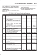
DTC P0106 – MAP System Performance
Step Action Value(s) Yes No
1 Was the “On-Board Diagnostic (OBD) System Check”
performed?
— Go to
Step 2
Go to
OBD
System
Check
2 1. Ignition “ON”, engine “OFF”.
2. Review and record Tech 2 Failure Records data.
3. Operate the vehicle within Failure Records
conditions as noted.
4. Using a Tech 2, monitor “DTC” info for DTC P0106.
Does the Tech 2 indicate DTC P0106 failed?
— Go to
Step 4
Go to
Step 3
3 1. Check for the following conditions:
B Vacuum hoses disconnected, damaged, or
incorrectly routed
B Intake manifold vacuum leaks
B Vacuum leaks at throttle body
B Vacuum leaks at EGR valve flange and pipes
B Crankcase ventilation valve faulty, missing or
incorrectly installed.
2. If a problem is found, repair as necessary.
Was a problem found?
— Verify repair
Refer to
Diagnostic
Aids
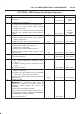
4 1. Disconnect the MAP sensor electrical connector.
2. Observe the MAP value displayed on the Tech 2.
Is the MAP value near the specified value?
11 kPa Go to
Step 5
Go to
Step 13
5 1. Connect a test light between B+ and the MAP
sensor signal circuit at the MAP sensor harness
connector.
2. Observe the MAP value displayed on the Tech 2.
Is the MAP value near the specified value?
105 kPa Go to
Step 6
Go to
Step 9
6 1. Jumper the 5 volt reference circuit and the MAP
signal circuit together at the MAP sensor harness
connector.
2. Observe the MAP value displayed on the Tech 2.
Is the MAP value near the specified value?
104 kPa Go to
Step 7
Go to
Step 8
7 1. Ignition “OFF”.
2. Disconnect the PCM and check the sensor ground
circuit for high resistance, an open between the
PCM and the MAP sensor, or for a poor connection
at the PCM.
3. If a problem is found, repair as necessary.
Was a problem found?
— Verify repair Go to
Step 11