
Workshop Manual


6E–147
6VE1 3.5L ENGINE DRIVEABILITY AND EMISSIONS
locks, improperly formed or damaged terminals, and
poor terminal-to-wire connection.
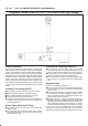
B Damaged harness – Inspect the wiring harness for
damage. If the harness appears to be OK, observe the
MAP display on the Tech 2 while moving connectors
and wiring harnesses related to the sensor. A change
in the display will indicate the location of the fault.
If DTC P0108 cannot be duplicated, the information
included in the Failure Records data can be useful in
determining vehicle mileage since the DTC was last set. If
it is determined that the DTC occurs intermittently,
performing the DTC P1108 Diagnostic Chart may isolate
the cause of the fault.
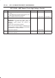
DTC P0108 – MAP Sensor Circuit High Voltage
Step Action Value(s) Yes No
1 Was the “On-Board Diagnostic (OBD) System Check”
performed?
— Go to
Step 2
Go to
OBD
System
Check
2 1. If the engine idle is rough, unstable or incorrect,
repair the idle problem before using this chart. Refer
to
Symptoms
section.
2. With the engine idling, note the MAP value on the
Tech 2.
Is the MAP reading above the specified value?
90 kPa Go to
Step 4
Go to
Step 3
3 1. Ignition “ON”, engine “OFF”.
2. Review and record Tech 2 Failure Records data.
3. Operate the vehicle within Failure Records
conditions as noted.
4. Using a Tech 2, monitor “DTC” info for DTC P0108.
Does the Tech 2 indicate DTC P0108 failed this
ignition?
— Go to
Step 4
Refer to
Diagnostic
Aids
4 1. Ignition “OFF”.
2. Disconnect the MAP sensor electrical connector.
3. Ignition “ON”.
4. Note the MAP sensor voltage displayed on the Tech
2. (If no, start with diagnostic chart for other sensors
in the circuit and see if 5V returns.)
Is the MAP sensor voltage at the specified value?
11 kPa 0.0
V
Go to
Step 5
Go to
Step 6
5 Probe the sensor ground circuit with a test light to B+.
Is the test light “ON”?
— Go to
Step 7
Go to
Step 9
6 1. Check the MAP signal circuit for a short to voltage or
a short to the 5 volt reference circuit.
2. If the MAP sensor signal circuit is shorted, repair
circuit as necessary.
Was the MAP sensor signal circuit shorted?
— Verify repair Go to
Step 11
7 1. Check for a poor sensor ground terminal connection
at the MAP sensor electrical connector.
2. If a problem is found, replace the faulty terminal.
Did the terminal require replacement?
— Verify repair Go to
Step 8
8 Check for a plugged or leaking vacuum supply to the
MAP sensor.
Is the vacuum supply plugged or leaking?
— Verify repair Go to
Step 12
9 1. Check for a poor sensor ground terminal connection
at the PCM.
2. If a problem is found, replace the faulty terminal.
Did the terminal require replacement?
— Verify repair Go to
Step 10