
Workshop Manual


1A–92
HEATING, VENTILATION AND AIR CONDITIONING (HVAC)
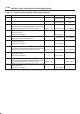
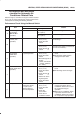
Step Action Value(s) Yes No
1 1. Allow the engine to idle until it completely warms up.
2. Turn the starter switch to the OFF position.
3. Place a 60–watt lamp approximately 15 cm from the
sun sensor.
NOTE: This procedure is best performed at night or in
a dark, unlit area.
Is the action complete?
— Go to
Step 2
—
2 Simultaneously press and hold the RESET key and the
CLOCK key (display unit).
Move the starter switch to start the engine.
Does DIAG appear on the display?
— Go to
Step 3
Replace
display unit
3 Press the COMPUTER MODE key.
Does DIAG AIRCON appear on the display?
— Go to
Step 4
Replace
audio unit
4 NOTE: A ’1’ should appear in the set temperature
segment of the display.
Does ’0’ appear in the outside air segment of the
display?
— Go to
Step 6
Go to
Step 5
5 Repair or replace damaged parts.
NOTE: Refer to
Step 1 Trouble Code Table.
Is the action complete?
— Go to
Step 1
—
6 Press and release the Y fan switch (one time only).
NOTE: A ’2’ should appear in the set temperature
segment of the display.
Does ’0’ appear in the outside air segment of the
display?
— Go to
Step 8
Go to
Step 7
7 Repair or replace damaged parts.
NOTE: Refer to
Step 2 Trouble Code Table.
Is the action complete?
— Go to
Step 1
—
8 Press and release the Y fan switch (one time only).
NOTE:
B Refer to
Step 3 Sensor Output Check for a sample
output value.
B A ’3’ should appear in the set temperature
segment of the display.
Does the correct sensor output value appear in the
outside air segment of the display?
— Go to
Step 10
Go to
Step 9
9 Repair or replace damaged parts.
NOTE: Refer to
Trouble Spot Inspection.
Is the action complete?
— Go to
Step 1
—
10 Press and release the Y fan switch one time only.
NOTE: Refer to
Step 4
(Operation Check) for display
readings and inspection steps.
Are all parts operating normally? — Go to
Step 12
Go to
Step 11