
Workshop Manual


6E–350
6VE1 3.5L ENGINE DRIVEABILITY AND EMISSIONS
Diagnostic Aids
B Damaged harness–Inspect the wiring harness for
damage. If the harness appears to be OK, observe the
fuel level display on the scan tool while moving
connectors and wiring harnesses related to the sensor.
A change in the display will indicate the location of the
fault.
Test Description
Number(s) below refer to the step number(s) on the
Diagnostic Chart.
2. The ETC and MAP sensors share a ground at PCM
terminal D9.
9. Equates the resistance values at various float
positions to the following fuel gauge readings:
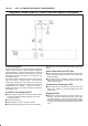
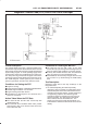
DTC P0463– Fuel Level Sensor Circuit –High Voltage
Step Action Value(s) Yes No
1 Was the “On-Board Diagnostic (OBD) System Check”
performed?
— Go to
Step 2
Go to
OBD
System
Check
2 1. Disconnected the fuel level sensor harness from its
connector at the fuel tank.
2. Ignition “ON”, engine “OFF”.
3. Using a DVM, measure the voltage between the
sensor harness positive and ground wires.
Is the voltage approximately equal to the specified
value?
5 V Go to
Step 8
Go to
Step 3
3 With the negative DVM lead connected to ground, use
the positive DVM lead to probe the sensor ground wire
with the harness still disconnected.
Does the DVM indicate a short to a voltage source?
— Go to
Step 4
Go to
Step 5
4 Repair short to voltage between the sensor and the
PCM.
Is the repair complete?
— Verify repair —
5 With the negative DVM lead connected to ground, use
the positive DVM lead to probe the sensor positive wire
with the harness still disconnected.
Does the DVM indicate a voltage greater than the
specified value?
5 V Go to
Step 4
Go to
Step 6
6 Open circuit between the PCM connector and the fuel
level sensor?
— Verify repair Go to
Step 7
7 Replace the PCM.
IMPORTANT: The replacement PCM must be
programmed. Refer to
On-Vehicle Service
in
Powertrain Control Module and Sensors
for
procedures. And also refer to latest Service Bulletin.
Check to see if the Latest software is released or not.
And then Down Load the LATEST PROGRAMMED
SOFTWARE to the replacement PCM.
Is the action complete?
— Verify repair —
8 Remove the fuel level sensor and check the following:
B Does the arm move freely?
B Are the wire leads shorted together?
B Do the resistance values match the specification
chart?
Was a problem found?
— Go to
Step 9
Go to
Step 7
9 Replace the fuel level sensor.
Is the repair complete?
— Verify repair —