
Workshop Manual


6E–355
6VE1 3.5L ENGINE DRIVEABILITY AND EMISSIONS
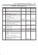
DTC P0502 – VSS Circuit Low Input (Cont'd)
Step NoYesValue(s)Action
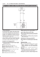
10 1. Ignition “OFF”.
2. Disconnect the MAF sensor. The connector
attaches the VSS wires from the transmission
harness to the left-side engine harness.
3. Disconnect the black 16-way connector.
4. Select a terminal adapter from kit J 35616 that can
be used with a jumper to supply B+ to the blue wire
with a yellow tracer (transmission side of the
connector).
5. Use another terminal adapter to attach a voltmeter
to the light-green wire with a white tracer (next to the
wire in the previous step.)
6. Disconnect the blue connector next to the black
16-way connector, and locate the black/red tracer
wire at one corner of the blue connector. The
black/red wire is the VSS ground. Use a terminal
adapter to attach a jumper to ground to the
black/red VSS ground wire at the transmission side
of the blue connector.
7. Raise the rear wheels off the ground with
transmission in neutral.
Does the DVM toggle back and forth between 0.6 V and
10 V as the wheels (and driveshaft) are rotated?
— Go to
Step 11
Go to
Step 12
11 Replace the VSS.
Is the action complete?
— Verify repair —
12 Check for an open or short between the PCM and the
speedometer.
Was a problem found?
— Verify repair Go to
Step 13
13 Replace the PCM.
IMPORTANT: The replacement PCM must be
programmed. Refer to
On-Vehicle Service
in
Powertrain Control Module and Sensors
for
procedures.
ANd also refer to latest Service Bulletin.
Check to see if the Latest software is released or not.
And then Down Load the LATEST PROGRAMMED
SOFTWARE to the replacement PCM.
Is the action complete?
— Verify repair —