
Workshop Manual


1A–108
HEATING, VENTILATION AND AIR CONDITIONING (HVAC)
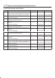
Chart A: Does Not Work At All
Step Action Value(s) Yes No
1 1. Turn on the ignition switch (the engine is run).
2. Disconnect the mode actuator connector (C–42)
3. Select VENT pressing the mode actuator.
Is the battery voltage provided on a regular interval
between the harness side connector terminal
No.C42–1 (+) and No.C42–5 (-)?
— Go to
Step 3
Go to
Step 2
2 Replace the auto air conditioner control unit.
Is the action complete?
— Varify repair —
3 Turn on the DEF mode switch.
Is the battery voltage provided on a regular interval
between the chassis side connector terminal
No.C42–5 (+) and No.C42–1 (-)?
— Go to
Step 5
Go to
Step 4
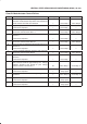
4 Replace the auto air conditioner control unit.
— Varify repair —
5 Is there continuity between the harness side connector
terminal No.C42–1 and No.I19–4?
— Go to
Step 7
Go to
Step 6
6 Repair an open circuit between terminal No.C42–1 and
No.I19–4.
Is the action complete?
— Go to
Step 5
—
7 Is there continuity between the harness side connector
terminal No.C42–5 and No.I19–3?
— Go to
Step 9
Go to
Step 8
8 Repair an open circuit between terminal No.C42–5 and
No.I19–3.
Is the action complete?
— Verify repair —
9 Replace the mode actuator.
— Verify repair —