
Workshop Manual


HEATING, VENTILATION AND AIR CONDITIONING (HVAC)
1A–109
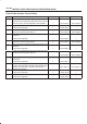
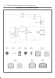
Chart B: Mode Actuator Control Failure
Step Action Value(s) Yes No
1 Turn on the ignition switch (the engine is run).
Dose the mode actuator fully stroke when the defrost
mode and the vent mode are selected?
— Go to
Step 3
Go to
Step 2
2 Repair or replace the mode door or the link unit.
Is the action complete?
— Go to
Step 1
—
3 Is there continuity between the harness side connector
terminal No.C42–9 and No.I20–11?
— Go to
Step 5
Go to
Step 4
4 Repair an open circuit between terminal No.C42–9 and
No.I20–11.
Is the action complete?
— Go to
Step 3
—
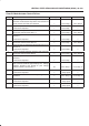
5 Is there continuity between the harness side connector
terminal No.C42–3 and No.I20–10?
— Go to
Step 7
Go to
Step 6
6 Repair an open circuit between terminal No.C42–3 and
No.I20–10.
Is the action complete?
— Go to
Step 5
—
7 Is there continuity between harness side connector
terminal No.C42–4 and No.I20–8?
— Go to
Step 9
Go to
Step 8
8 Repair an open circuit between terminal No.C42–4 and
No.I20–8.
Is the action complete?
— Go to
Step 7
—
9 Is sum of the voltage between the following harness
side connector terminal approximately 5V? Voltage
between No.I20–8 and No.I20–10 plus voltage
between No.I20–8 and No.I20–11
5V Go to
Step 11
Go to
Step 10
10 Replace the actuator.
Is the action complete?
— Verify repair —
11 Dose the mode actuator work normally through manual
operation?
— Go to
Step 13
Go to
Step 12
12 Replace the sensor.
Is the action complete?
— Verify repair —
13 Replace the auto air conditioner control unit.
Is the action complete?
— Verify repair —