
Workshop Manual


6E–403
6VE1 3.5L ENGINE DRIVEABILITY AND EMISSIONS
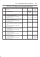
DTC P1125 – ETC Limit Performance Model (Cont'd)
Step NoYesValue(s)Action
7 Check the following items;
1. AP1, AP2 or AP3 signal circuit or 5 voltage supply
circuit for a poor connection.
2. AP1, AP2 or AP3 signal circuit or 5 voltage supply
circuit for high resistance between the PCM and the
AP1, AP2 or AP3 sensor.
3. If a problem is found, repair wiring harness as
necessary.
Was a problem found?
— Verify repair Go to
Step 9
8 Replace the AP sensor.
Is the action complete?
— Verify repair —
9 Replace the PCM.
IMPORTANT: The replacement PCM must be
programmed. Refer to
ON-Vehicle Service in Power
Control Module and Sensors for procedures.
And also refer to latest Service Bulletin.
Check to see if the latest software is released or not.
And then Down Load the LATEST PROGRAMMED
SOFTWARE to the replacement PCM.
Is the action complete?
— Verify repair —