
Workshop Manual


6E–460
6VE1 3.5L ENGINE DRIVEABILITY AND EMISSIONS
Diagnostic Aids
An intermittent may be caused by the following:
B Poor connections.
B Misrouted harness.
B Rubbed through wire insulation.
B Broken wire inside the insulation.
Check for the following conditions:
B Poor connection at PCM-Inspect harness connectors
for backed out terminals, improper mating, broken
locks, improperly formed or damaged terminals, and
poor terminal to wire connection.
B Damaged harness-Inspect the wiring harness for
damage. If the harness appears to be OK, observe the
moving connectors and wiring harnesses related to the
sensor.
A change in the display will indicate the location of
the fault. If DTC P1310 cannot be duplicated, the
information included in the Failure Records data can
be useful in determined vehicle mileage since the
DTC was last set.
If it is determined that the DTC occurs intermittently,
performing the DTC P1310 Diagnostic Chart may
isolate the cause of the fault.
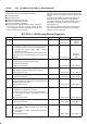
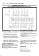
DTC P1310 - ION Sensing Module Diagnostic
Step Action Value(s) Yes No
1 Was the “On-Board (OBD) System Check” performed?
— Go to
Step 2
Go to
OBD
System
Check
2 1. Ignition “ON”, engine “OFF”.
2. Review and record Tech 2 Failure Records data.
3. Operate the vehicle within Failure Records
conditions as noted.
4. Using a Tech 2, monitor “DTC” info for DTC P1310.
Does the Tech 2 indicate DTC P1310 failed this
ignition?
— Go to
Step 3
Refer to
Diagnostic
Aids
3 1. Ignition “OFF”.
2. Disconnect the ION Sensing module.
3. Disconnect the PCM.
Is the action complete?
— Go to
Step 4
Go to
Step 3
4 Check the ION Sensing harness between the PCM and
ION Sensing module circuit harness connector.
Was a problem found?
— Verify repair Go to
Step 6
5 1. Disconnect the ignition coil.
Is the action complete?
— Go to
Step 6
Go to
Step 5
6 Check the ION Sensing harness between the ignition
coil and ION Sensing module circuit at the ION Sensing
Module harness connector.
Was a problem found?
— Verify repair Go to
Step 7
7 Check the following items;
1. Ignition coil and ignition coil circuit.
2. Ignition coil ground circuit for a poor connection.
3. If a problem is found, repair wiring harness as
necessary.
Was a problem found?
— Verify repair Go to
Step 8
8 Replace the Ignition coil.
Is the action complete?
— Verify repair Go to
Step 9
9 Check the following items;
1. ION Sensing module ground circuit for a poor
connection.
2. If a problem is found, repair wiring harness as
necessary.
Was a problem found?
— Verify repair Go to
Step 10