
Workshop Manual


6E–477
6VE1 3.5L ENGINE DRIVEABILITY AND EMISSIONS
Diagnostic Trouble Code (DTC)
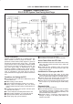
P1441 EVAP System Flow During Non-Purge
060RY00398
Circuit Description
Canister purge is controlled by a solenoid valve that
allows manifold vacuum to purge the canister. The
powertrain control module (PCM) supplies a ground to
energize the solenoid valve (purge “ON”). The EVAP
purge solenoid control is pulse-width modulated (PWM)
or turned “ON” and “OFF” several times a second. The
duty cycle (pulse width) is determined by engine
operating conditions including load, throttle position,
coolant temperature and ambient temperature. The duty
cycle is calculated by the PCM and the output is
commanded when the appropriate conditions have been
met.
Conditions for Setting the DTC
B No active ECT sensor, IAT sensor, MAP sensor, or TP
sensor DTCs set.
B BARO reading is above 85 kPa.
B Engine coolant temperature is below 70°C (158°F).
B Start-up intake air temperature (IAT) and start-up
engine coolant temperature (ECT) are both above 5°C
(41°F).
B The difference between start-up ECT and start-up IAT
is less than 25°C (45°F).
B TP sensor indicates a throttle position above 12%.
B Battery voltage is between 11.5 volts and 16 volts.
B Engine speed is between 800 and 6,000 RPM.
B Canister purge duty cycle is below 3%.
B Fuel level is between 15% and 85%.
B All conditions are present for at least 3 seconds.
Action Taken When the DTC Sets
B The PCM will illuminate the malfunction indicator lamp
(MIL) after the second consecutive trip in which the
fault is detected.
B The PCM will store conditions which were present
when the DTC was set as Freeze Frame and in the
Failure Records data.
Conditions for Clearing the MIL/DTC
B The PCM will turn the MIL “OFF” on the third
consecutive trip cycle during which the diagnostic has
been run and the fault condition is no longer present.
B A history DTC P1441 will clear after 40 consecutive
warm–up cycles have occurred without a fault.
B DTC P1441 can be cleared by using the Tech 2 “Clear
Info” function or by disconnecting the PCM battery
feed.
Diagnostic Aids
Check for the following conditions:
B Poor connection at PCM – Inspect harness connectors
for backed-out terminals, improper mating, broken
locks, improperly formed or damaged terminals, and
poor terminal-to-wire connection.
B Damaged harness – Inspect the wring harness for
damage. A change in the display will indicate the
location of the fault.