
Workshop Manual


6E–481
6VE1 3.5L ENGINE DRIVEABILITY AND EMISSIONS
locks, improperly formed or damaged terminals, and
poor terminal to wire connection.
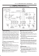
B Damaged harness - Inspect the wiring harness for
damage. If the harness appears to be OK, observe the
Mass Air Flow, TP sensor 1, TP sensor 2 display on the
Tech 2 while moving connectors and wiring harnesses
related to the sensor.
B Plugged intake air duct or filter element
B A wide - open throttle acceleration from a stop should
cause the mass air flow displayed on a Tech 2 to
increase from about 3 – 6 g/s at idle to 100 g/s or
greater at the time of the 1 – 2 shift. If not, check for a
restriction.
A change in the display will indicate the location of
the fault. If DTC P1514 cannot be duplicated, the
information included in the Failure Records data can
be useful in determining vehicle mileage since the
DTC was last set.
If it is determined that the DTC occurs intermittently,
performing the DTC P1514 Diagnostic Chart may
isolate the cause of the fault.
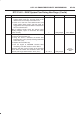
DTC P1514 - TPS-MAF Correlation Error
Step Action Value(s) Yes No
1 Was the “On-Board (OBD) System Check” performed?
— Go to
Step 2
Go to
OBD
System
Check
2 Was the “Electric Throttle Control (ETC) System
Check” performed?
— Go to
Step 3
Go to
ETC
System
Check
3 1. Ignition “ON”, engine “OFF”.
2. Review and record Tech 2 Failure Records data.
3. Operate the vehicle within Failure Records
conditions as noted.
4. Using a Tech 2, monitor “DTC” info for DTC P1514.
Does the Tech 2 indicate DTC P1514 failed this
ignition?
— Go to
Step 4
Refer to
Diagnostic
Aids
4 1. Start the engine.
2. With the engine idling, monitor “MAF Frequency”
display on the Tech 2.
Is the “MAF Frequency” below the specified value?
6 ∼ 10 g/s Go to
Step 5
Go to
Step 8
5 1. Ignition “OFF”.
2. Disconnect the MAF sensor connector.
3. Ignition “ON”, engine idling.
4. Using a Tech 2, monitor “MAF Frequency”.
Does the Tech 2 indicate a “MAF Frequency” at the
specified value?
0g/s Go to
Step 6
Go to
Step 7
6 Replace the MAF sensor.
Is the action complete?
— Verify repair Go to
Step 9
7 1. Check the MAF harness for incorrect routing near
high voltage components (solenoids, relays,
motors).
2. If incorrect routing is found, correct the harness
routing.
Was a problem found?
— Verify repair Go to
Step 19
8 1. With the engine idling, monitor “MAF Frequency”
display on the Tech 2.
2. Quickly snap open throttle to wide open throttle
while under a road load and record value.
Does the Tech 2 indicate a “MAF Frequency” at the
specified value?
6 ∼ 10 g/s Go to
Step 6
Go to
Step 9
9 1. Ignition“ON”, engine not running.
2. Observe the MAP reading on the Tech 2.
Is the MAP reading less than the specified value?
65kPa Go to
Step 10
Go to
Step 13