
Workshop Manual

6E–485
6VE1 3.5L ENGINE DRIVEABILITY AND EMISSIONS
moving connectors and wiring harnesses related to the
sensor.
A change in the display will indicate the location of
the fault. If DTC P1515 cannot be duplicated, the
information included in the Failure Records data can
be useful in determing vehicle mileage since the
DTC was last set.
If it is determined that the DTC occurs intermittently,
performing the DTC P1515 Diagnostic Chart may
isolate the cause of the fault.
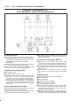
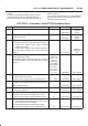
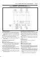
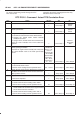
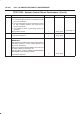
DTC P1515 - Command - Actual TPS Correlation Error
Step Action Value(s) Yes No
1 Was the “On-Board (OBD) System Check” performed?
— Go to
Step 2
Go to
OBD
System
Check
2 Was the “Electric Throttle Control (ETC) System
Check” performed?
— Go to
Step 3
Go to
ETC
System
Check
3 1. Ignition “ON”, engine “OFF”.
2. Review and record Tech 2 Failure Records data.
3. Operate the vehicle within Failure Records
conditions as noted.
4. Using a Tech 2, monitor “ DTC” info for DTC P1515.
Does the Tech 2 indicate DTC P1515 failed this
ignition?
— Go to
Step 4
Refer to
Diagnostic
Aids
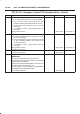
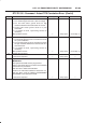
4 Observe the TP angle reading on the Tech 2 while
slowly opening the throttle.
Does the TP angle increase steadily and evenly from
the closed throttle value to the wide open throttle
value?
Closed
throttle TP
sensor 1 =8 ∼
10 % TP
sensor 2 =90
∼ 92 % Wide
open throttle
TP sensor 1
=90 ∼ 92 %
TP sensor 2
=8 ∼ 10 %
Go to
Step 5
Go to
Step 8
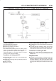
5 1. Ignition “OFF”.
2. Disconnect the DC motor.
Is the DC motor reading near the specified value?
0.3 ∼ 100 W Go to
Step 6
Go to
Step 7
6 Check the DC motor harness between the PCM and
DC Motor circuit at the DC motor harness connector.
Was a problem found?
— Verify repair Go to
Step 8
7 Replace the DC motor.
Is the action complete?
— Verify repair Go to
Step 6
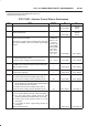
8 1. Disconnect the TP sensor.
2. Observe the TP sensor reading on the Tech 2.
Is the TP sensor reading near the specified value?
0V Go to
Step 9
Go to
Step 10
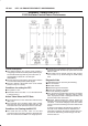
9 1. Connect a test light between the 5Volt reference
circuit and the TP1 and TP2 sensor signal circuit at
the TP sensor harness connector.
2. Observe the TP sensor reading on the Tech2.
Is the TP sensor reading near the specified value?
5V Go to
Step 12
Go to
Step 11