
Workshop Manual

6E–487
6VE1 3.5L ENGINE DRIVEABILITY AND EMISSIONS
Diagnostic Trouble Code (DTC)
P1516 Command - Actual TPS Correlation Error
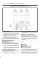
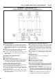
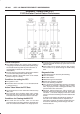
D06RY00111
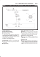
Circuit Description
B The throttle position (TP) sensor circuit provides a
voltage signal relative to throttle position (blade angle).
The throttle blade angle will vary from about 8% at
closed throttle to about 92 % at wide open throttle
(WOT).
B The DC motor circuit provides a voltage signal relative
to command throttle position (blade angle).
B This DTC detects the difference between actual
throttle position and command throttle position in
steady state.
Conditions for setting the DTC
B The ignition is “ON”.
B Throttle Actuation mode is normal.
B Command Throttle position-Actual Throttle position is
less than 8 % when desired TPS is steady within 0.5
% for 30 seconds within test samples (30 second)
Action Taken When the DTC Sets
B The PCM will illuminate the malfunction indicator lamp
(MIL) the first time the fault is detected.
B The PCM calculates an air flow value based on idle air
control valve position, throttle position, RPM and
barometric pressure.
B The PCM will store conditions which were present
when the DTC was set as Freeze Frame and in the
Failure Records data.
Conditions for Clearing the MIL/DTC
B The PCM will turn the MIL “OFF” on the third
consecutive trip cycle during which the diagnostic has
been run and the fault condition is no longer present.
B A history DTC P1516 will clear after 40 consecutive trip
cycles during which the warm up cycles have occurred
without a fault.
B DTC P1516 can be cleared using the Tech 2 “Clear
Info” function or by disconnecting the PCM battery
feed.
Diagnostic Aids
An intermittent may be caused by the following:
B Poor connections.
B Misrouted harness.
B Rubbed through wire insulation.
B Broken wire inside the insulation.
Check for the following conditions:
B Poor connection at PCM-Inspect harness connectors
for backed out terminals, improper mating, broken
locks, improperly formed or damaged terminals, and
poor terminal to wire connection.
B Damaged harness - Inspect the wiring harness for
damage. If the harness appears to be OK, observe the
TP sensor 1, TP sensor 2 display on the Tech2 while
moving connectors and wiring harnesses related to the
sensor.
A change in the display will indicate the location of
the fault. If DTC P1516 cannot be duplicated, the