
Workshop Manual

6E–491
6VE1 3.5L ENGINE DRIVEABILITY AND EMISSIONS
If it is determined that the DTC occurs intermittently,
performing the DTC P1523 Diagnostic Chart may
isolate the cause of the fault.
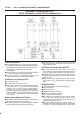
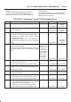
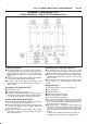
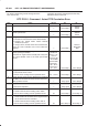
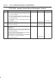
DTC P1523 - Actuator Control Return Performance
Step Action Value(s) Yes No
1 Was the “On-Board (OBD) System Check” performed?
— Go to
Step 2
Go to
OBD
System
Check
2 Was the “Electric Throttle Control (ETC) System
Check” performed?
— Go to
Step 3
Go to
ETC
System
Check
3 Observe the TP angle reading on the Tech 2 while
slowly opening the throttle.
Does the TP angle increase steadily and evenly from
the closed throttle value to the wide open throttle
value?
Closed
throttle TP
sensor 1 =8 ∼
10 % TP
sensor 2 =90
∼ 92 % Wide
open throttle
TP sensor 1
=90 ∼ 92 %
TP sensor 2
=8 ∼ 10 %
Go to
Step 4
Go to
Step 7
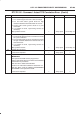
4 1. Ignition “OFF”.
2. Disconnect the DC motor.
Is the DC motor reading near the specified value?
0.3 ∼ 100 W Go to
Step 5
Go to
Step 6
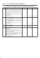
5 Check the DC motor harness between the PCM and
DC Motor circuit at the DC motor harness connector.
Was a problem found?
— Verify repair Go to
Step 7
6 Replace the DC motor.
Is the action complete?
— Verify repair Go to
Step 5
7 1. Disconnect the TP sensor.
2. Observe the TP sensor reading on the Tech 2.
Is the TP sensor reading near the specified value?
0V Go to
Step 8
Go to
Step 9
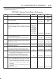
8 1. Connect a test light between the 5 Volt reference
circuit and the TP1 and TP2 sensor signal circuit at
the TP sensor harness connector.
2. Observe the TP sensor reading on the Tech 2.
Is the TP sensor reading near the specified value?
5V Go to
Step 11
Go to
Step 10
9 Check the following items;
1. TP1 and TP2 signal circuit for a short to voltage.
2. TP1 and TP2 sensor ground circuit for high
resistance between the PCM and the TP sensor.
3. TP1and TP2 sensor ground circuit for a poor
connection.
4. If a problem is found, repair wiring harness as
necessary.
Was a problem found?
— Verify repair Go to
Step 12