
Workshop Manual


7A–35
AUTOMATIC TRANSMISSION (4L30–E)
5.Check that cable moves smoothly, lightly pulling outer
cable rearward.
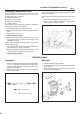
6.Connect lock adjust, aligning “T” mark in the “Up”
position.
256R200003
7.About following installation steps, refer to
Selector
Lever in this section.
8.Check the shift lock operation:
a. Selector lever should not be moved out of “P”
position with ignition key in “Lock” position.
b. Selector lever can be moved out of “P” position with
ignition key in “ON”position only when brake pedal
is depressed.
c. ignition key can be turned to “LOCK” position only
when selector lever is in “P” position (key can be
pulled out).
9.If a. and c. fail, readjust cable. If b. fails, readjust
connector wiring and brake pedal switch.
Mode Switch
Removal
1.Place selector lever in neutral.
2.Disconnect battery ground cable.
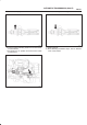
3.Remove mode switch cover (1) (V6).
4.Disconnect selector lever (2) from the mode switch.
5.Remove bracket with cable (3).
6.Disconnect transmission harness from the mode
switch connector (4).
7.Remove bracket with mode switch connector from
the transmission case.
8.Remove mode switch connector (4) from the bracket
(5).
9.Remove two mode switch bolts and nut then remove
mode switch (6).
210RW014