
Workshop Manual


7A–36
AUTOMATIC TRANSMISSION (4L30–E)
Installation
To install, follow the removal steps in the reverse order,
noting the following points;
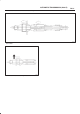
1.Torque
Mode switch bolt: 13 N•m (113 lb in)
Selector lever nut: 23 N•m (17 lb ft)
2.Mode switch setting procedure
Perform either of the following adjustment
procedures:
Procedure 1
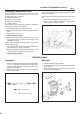
a. Place selector lever in neutral.
b. Remove selector lever from the mode switch.
c. Remove the mode switch cover.
d. Loosen the two 10 mm screws.
e. Rotate the mode switch until the slot in the mode
switch housing aligns with the selector shaft
bushing, and insert a 3/32 in. (2.4 mm) drill bit or
punch (1) into the slot.
f. Tighten the screws to 13 N·m (113 lb in).
g. After completing adjustment, snap the mode
switch cover into place.
h. Reinstall the selector lever.
249RW001
Procedure 2
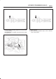
a. Place selector lever in neutral.
b. Disconnect transmission harness connector from
mode switch connector.
c. Remove mode switch connector with bracket from
the transmission case.
d. Connect multimeter (resistance mode) to
terminals 1(E) and 4(H) on mode switch connector.
e. Loosen two mounting screws.
f. Rotate mode switch slightly in both directions to
determine the range (approx. 5 degrees) of
electrical contact.
g. Position mode switch in middle of contact range.
h. Tighten two mounting screws.
i. Remove multimeter and install mode switch
harness connector with bracket to the
transmission case.
j. Connect transmission harness connector to mode
switch connector.
F07RW003