
Workshop Manual


POWER–ASSISTED STEERING SYSTEM
2A–13
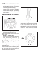
Caster (1) is the vertical tilting of the wheel axis either
forward or backward (when viewed from the side of the
vehicle). A backward tilt is positive (+) and a forward tilt is
negative (-). On the short and long arm type suspension
you cannot see a caster angle without a special
instrument, but if you look straight down from the top of
the upper control arm to the ground, the ball joints do not
line up (fore and aft) when a caster angle other than 0
degree is present. With a positive angle, the lower ball
joint would be slightly ahead (toward the front of the
vehicle) of the upper ball joint center line.
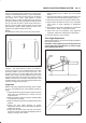
Toe-in:
This illustration shows view from the top of the vehicle.
480RS003
Toe-in is the measured amount the front wheels are
turned in. The actual amount of toe-in is normally a
fraction of a degree. Toe-in is measured from the center
of the tire treads or from the inside of the tires. The
purpose of toe-in is to insure parallel rolling of the front
wheels and to offset any small deflections of the wheel
support system which occurs when the vehicle is rolling
forward. Incorrect toe-in results in excessive toe-in and
unstable steering. Toe-in is the last alignment to be set in
the front end alignment procedure.
Inspection
Before making any adjustments affecting caster, camber
or toe-in, the following front end inspection should be
made.
1.Inspect the tires for proper inflation pressure. Refer to
Main Data and Specifications in Wheel and Tire
System
section.
2.Make sure that the vehicle is unladen condition (With
no passenger or loading).
3.Make sure that the spare tire is installed at the normal
position.
4.Inspect the front wheel bearings for proper
adjustment. Refer to
Front Hub and Disc Overhaul in
Suspension
section.
5.Inspect the ball joints and tie rod ends. If excessive
looseness is noted, correct before adjusting. Refer to
Steering Linkage
in this section.
6.Inspect the wheel and tires for run-out. Refer to
Wheel Replacement in Wheel and Tire System
section.
7.Inspect the trim height. If not within specifications, the
correction must be made before adjusting caster.
8.Inspect the steering unit for looseness at the frame.
9.Inspect shock absorbers for leaks or any noticeable
noise. Refer to
Shock Absorber in Suspension
section.
10.Inspect the control arms or stabilizer bar attachment
for looseness. Refer to
Suspension
section.
11.Inspect the front end alignment using alignment
equipment. Follow the manufacturer’s instructions.
12.Park the vehicle on a level surface.
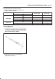
Trim Height Adjustment
Adjust the trim height (1) by means of the adjusting bolt on
the height control arms.
CAUTION: When adjusting front end alignment, be
sure to begin with trim height first, as it may change
other adjusted alignments.
450RS003
410RS001