
Workshop Manual


2A–14
POWER–ASSISTED STEERING SYSTEM
1.Check and adjust the tire inflation pressures.
2.Park the vehicle on a level ground and move the front
of the vehicle up and down several times to settle the
suspension.
3.Make necessary adjustment with the adjusting bolt on
the height control arms.
Trim height: 119 ± 5 mm (4.69 ± 0.2 in)
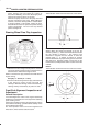
Caster Adjustment
The caster angle can be adjusted by means of the caster
shims (1) installed between the chassis frame (2) and
fulcrum pins.
Caster angle: 2°30’ ± 1°
CAUTION: Left and right side must be equal within
30’.
450RW006
450RS002
NOTE: Difference of the caster shim front/rear thickness
should be 3.6 mm (0.142 in) or less. Overall thickness of
caster shim and camber shim should be 10.8 mm
(0.425 in) or less.
Tighten the fulcrum pin bolt to the specified torque.
Torque: 152 N·m 112 ( lb ft)
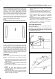
Camber Adjustment
The camber angle can be adjusted by means of the
camber shims (2) installed in position between the
chassis frame (1) and fulcrum pins
Camber angle: 0° ± 30’
King pin inclination: 12°30’ ± 30’
CAUTION: Left and right side must be equal within
30’.
450RW007
450RS005